Spartan 300 User manual

PRODUCT MANUAL
Model 300
© 2020 Spartan Tool LLC
Part #44292800 (Rev. F) 2020-00
Spartan Tool LLC |1618 Terminal Road |Niles, MI 49120
order by phone 800.435.3866 order online SpartanTool.com

2
WARNINGS ............................................................................................................ 4
INTRODUCTION........................................................................................................5
Service Information.............................................................................................................5
SPECIFICATIONS AND FEATURES........................................................................................6
SAFETY INSTRUCTIONS ................................................................................................7
300 with Dial-A-Cable Power Cable Feed ...................................................................................... 10
MACHINE FEATURES ..................................................................................................10
ASSEMBLY INSTRUCTIONS ............................................................................................11
Joining Cables ................................................................................................................ 11
Assembly..................................................................................................................... 11
Disassembly .................................................................................................................. 11
Loading Cable Into Machine .................................................................................................. 11
Assembly of Blades to Cable .................................................................................................. 13
Blades........................................................................................................................ 13
Optional Tools ................................................................................................................ 14
Optional Accessories.......................................................................................................... 14
OPERATION...........................................................................................................15
OPERATING THE POWER CABLE FEED ..................................................................................17
SPECIAL APPLICATIONS PROCEDURE ..................................................................................18
Cleaning Lines Through a Manhole ............................................................................................ 18
Rodding Farther than 75' (5/8" Cable*). . . . . . . . . . . . . . . . . . . . . . . . . . . . . . . . . . . . . . . . . . . . . . . . . . . . . . . . . . . . . . . . . . . . . . . . . . . . . . . . . . . . . . . . . 18
Main Sewer or Septic Tank Overrun............................................................................................ 18
Contents

3
MAINTENANCE INSTRUCTIONS ........................................................................................19
Instructions for Splicing or Repairing Cable .................................................................................... 19
Splicing Cable (Standard Single Wound Cable)................................................................................. 19
Splicing the .55 Magnum Cable and Installing New .55 Couplings .............................................................. 19
Changing Motor Brushes...................................................................................................... 21
Caring for Cables ............................................................................................................. 21
How to Install 5' Drum Anchor Cable .......................................................................................... 22
Machine Storage ............................................................................................................. 22
PARTS & ACCESSORIES ................................................................................................23
Model 300 (04221458) ........................................................................................................ 23
Model 300 Drum Complete (44129300)........................................................................................ 24
External Drum Assembly (02875900) .......................................................................................... 25
Clutch Assembly (04203300) .................................................................................................. 26
Model 300 Internal Drum (02875300).......................................................................................... 27
Model 300 Frame Assembly (04217000) ....................................................................................... 28
Wiring Diagram............................................................................................................... 30
PM Motor with Gear Box 300 (44290200) ...................................................................................... 31
300 Electrical Box Detail (04221458) ........................................................................................... 32
Assembly, Universal Anchor .55 (44292700).................................................................................... 32
5/8" Cable .................................................................................................................... 33
Universal Anchor Cable Assembly, .55"- 5/8" (44292700) ....................................................................... 33
.55" Magnum Cable........................................................................................................... 34
Air Bulb & Hose Assembly (44225800) ......................................................................................... 35
Optional Compact Lift (02884900)............................................................................................. 35
Optional Model 100 Drum Adapters........................................................................................... 36
Tool Box and Accessory Kit .................................................................................................... 38
Pneumatic Tire Upgrade Kit (44250700). . . . . . . . . . . . . . . . . . . . . . . . . . . . . . . . . . . . . . . . . . . . . . . . . . . . . . . . . . . . . . . . . . . . . . . . . . . . . . . . . . . . . . . . 40
Spartan Accessory Blades ..................................................................................................... 41
WARRANTY INFORMATION ............................................................................................42

4
Warnings
• Read the safety and operating instructions before using any Spartan Tool products. Drain and sewer cleaning can be dangerous if
proper procedures are not followed and appropriate safety gear is not utilized.
• Before starting unit, be sure to wear personal protective equipment such as safety goggles or face shield and protective clothing
such as gloves, coveralls or raincoat, rubber boots with metatarsal guards, and hearing protection.
• Drains and sewer can carry bacteria and other infectious micro-organisms or materials which can cause death or severe illness. Avoid
exposing eyes, nose, mouth, ears, hands, and cuts and abrasions to waste water or other potentially infectious materials, wash hands,
arms and other areas of the body, as needed, with hot, soapy water and, if necessary, flush mucous membranes with water. Also,
disinfect potentially contaminated equipment by washing such surfaces with a hot soapy wash using a strong detergent.
• For any questions, contact the company at the address shown below.
CALIFORNIA PROP. 65
This product may contain an
extremely small amount of lead in the
coating. Lead is a material known to
the State of California to cause cancer
or reproductive toxicity.
CONTACT US
Spartan Tool LLC
1618 Terminal Road
Niles, MI 49120
800.435.3866
SpartanTool.com

5
Introduction
The Spartan Model 300 electric drain and sewer cleaning machine has been designed and manufactured with high quality materials
and care in workmanship. The instructions in this manual have been prepared to ensure that, when followed, the Spartan Model 300 will
provide long and efficient service.
WARNING: It is the responsibility of the operator to read and understand the Product Manual
and other information provided and use the correct operating procedure. Machines should
be operated only by qualified operators. Failure to do so can result in personal injury, death, or
machine damage.
Read the entire manual before the initial start-up of the machine. It is important to know the correct operating procedures of the
machine and all safety precautions to prevent the possibility of property damage and/or personal injury.
NOTE: Information in this manual is current at the time of printing. Spartan Tool reserves the right
to make changes and improvements to its products at any time without notice or obligation.
SPARTAN MODEL 300
Unit Model Number
CONTACT US
Spartan Tool LLC
1618 Terminal Road
Niles, MI 49120
800.435.3866
SpartanTool.com
SERVICE INFORMATION
All requests for information, service, or parts should include machine serial number.
Additional copies of this Product Manual can be downloaded free of charge from
www.SpartanTool.com.
Unit Serial Number

6
Specifications and Features
Drum Capacity 75' of ⁄" cable or 100' of .55 Magnum cable
Cleaning Capacity up to 250'
Recommended Line Size 3" to 6" diameter
Motor
Permanent magnet; 115 volt AC (rectified);
1.25 amps (DC) @ 300 rpm (no load); 4.6 amps
(DC) 155 in-lb torque @ 160 rpm
Weight 101 lbs for a 300 Dial-A-Cable machine with 5'
anchor cable
Height 30" to top of handle (retracted)
41" to top of handle (extended)
Width 18"
Length 29" with Dial-A-Cable power feed
Drum Speed 300 rpm with no load
Cable Feed Spartan Dial-A-Cable Power Cable Feed
Frame Extra strength aluminum/magnesium alloy
• Heavy duty permanent magnet motor with reverse capability.
• Inner drum rotates independently of outer drum, virtually eliminates cable kinking, buckling, and controls torque buildup.
• Outer drum keeps dirt inside, off operator and work area.
• Air foot switch with cord assembly keeps both hands free for safe, easy operation.
• Compact, portable design.
• Extra-strength aluminum and magnesium alloy construction.
• Integral continuous belt stair skids.
• Retractable "sure-grip" extending handle.
IMPORTANT: FOR YOUR OWN SAFETY—Before assembling and operating this unit, read this
product manual carefully and completely. Learn the operation, applications and potential hazards
peculiar to this unit.
7
Use of any electrical equipment in a wet or damp environment can cause fatal shock if not properly guarded against by the operator.
1. Know your drain cleaning machine. Read this Product Manual carefully. Learn the operation, applications, and limitations of this
machine.
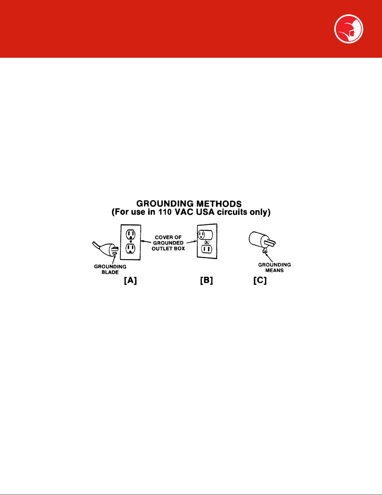
2. Grounding instructions: Before using your Spartan equipment, make sure that a properly grounded, (three hole) electrical outlet
is available. If not, as in older homes, use a three-prong adapter and connect the green pigtail or grounding lug to a known ground,
such as a (metallic) cold water pipe.
This tool should be grounded while in use to protect the operator from electric shock. The tool is equipped with a three-conductor
cored and proper grounding type receptacle. The green (or green and yellow) conductor in the cord is the grounding wire. Never
connect this wire to a live terminal. Units designed for use on less than 150 volts, have a plug that looks like that shown in Fig. 1A.
An adapter (Fig. 1B and 1C), is available for connecting three-prong plugs to two-prong receptacles (except in Canada). If such an
adapter is used, the green colored rigid ear, lug, or the like, extending from the adapter must be connected to a permanent ground
such as a properly grounded outlet box.
Safety Instructions
FIG. 1
This machine is equipped with a Ground Fault Circuit Interrupter (GFCI), which should always be plugged directly into an inspected,
grounded receptacle. Plug the three-pronged plug on the machine power cord with GFCI directly into an inspected grounded
outlet and then test and reset the GFCI.
Never cut off the grounding prong on the power cord for use in a two-hole outlet. Doing so cuts off your protection from shock.
Replace or repair all damaged power cords and components.

8
Safety Instructions
If an extension cord must be used, it must be approved, three-wire construction, equipped with a three-pronged plug, and in good
condition. Replace or repair damaged cords.
Do not use an undersized extension cord. An undersized cord will cause a drop in line voltage resulting in loss of power and
overheating. Use the following minimum gauges depending upon the length of the extension cord:
• 16 Ga.: for cords of less than 100 feet in length
• 14 Ga.: for cords of 100 feet to 150 feet in length
If in doubt, use the next heavier gauge. (The smaller the gauge number, the heavier the cord.) When the machine is used outdoors,
use only extension cords intended for use outdoors and so marked. Do not allow an extension cord to be exposed to water.
Don't assume that all three-hole outlets are properly installed. Check the outlet and also the adapter, if used, with an outlet testing
device which quickly indicates if a ground is connected. Correct a faulty test indication before proceeding.
4. Don't abuse cord. Never move or lift tool by cord or yank it to disconnect from receptacle. Keep cord from heat, oil, and sharp
edges.
5. Disconnect power cord. When not in use, before servicing, and when changing accessories, such as blades and cutters.
6. Guard against electric shock. Prevent body contact with grounded surfaces such as pipes, radiators, ranges, refrigerator
enclosures.
7. Avoid accidental starting. Don't move plugged-in tools. Make sure switch is in OFF position before plugging in power cord.
8. Stay alert. Watch what you are doing. Use common sense. Do not operate tool when you are tired.
9. Keep work area clean. Cluttered areas invite injuries.
10. Consider work area environment. Don't expose power tools to rain. Keep work area well lit.
Do not use tool in presence of flammable liquids or gases.
Avoid operating the machine in areas of standing water.
11. Dress properly. Do not wear loose clothing or jewelry. They can be caught in moving parts. Wear protective hair covering to
contain long hair.
Wear standard equipment (Spartan riveted gloves). Never grasp a rotating cable with a cloth or loose-fitting glove, which would get
wrapped around a cable.
Wear rubber boots and wear rubber gloves inside your Spartan cable handling gloves to further insulate yourself.
12. Use safety glasses. Guard against foreign material that might fly off cable.
13. Don't overreach. Keep proper footing and balance at all times.
3. Extension cords
DANGER: Improper use of an extension cord will cause death or severe injury. The GFCI on the
machine's power cord does not protect the operator from electrical shock along the extension cord.

9
Safety Instructions
WARNING: Continued drum rotation in reverse position will cause cable to "jump" out of drum. Possible
operator injury could result.
14. Keep children away. Do not let visitors contact tool or extension cord. All visitors should be kept away from work area.
15. Use recommended equipment and accessories. Use of improper equipment may be hazardous.
Don't force small cable with attachment to do the job of heavy-duty cable.
16. Don't force tool. It will do the job better and safer at the rate for which it was intended.
17. Remove punches and wrenches. Form a habit of checking to see that punches and adjusting wrenches are removed from tool
before turning it on.
18. Keep guards in place. Never operate machine with guard removed.
19. Avoid operating machine in reverse. Operating machine in reverse can result in cable damage and is used only to back tool away
from an obstruction.
20. Do not over torque cables. Excessive and/or continued rotation of the drum once an obstruction has been encountered will over
torque the cable. Kinking or breakage of cable may result. A worn cable can be identified as being very limber, kinked, or having
flattened coils on the outside of cable. Worn cable should be replaced as soon as possible.
21. Maintain tools with care. Keep tools sharp and clean for better and safer performance.
Follow instructions for lubricating and changing accessories.
Never use damaged power cords.
Inspect tool cords periodically and, if damaged, repair with proper Spartan replacement parts.
Inspect extension cords periodically and replace if damaged.
Keep handles dry, clean, and free from oil and grease.
22. Check damaged parts. Before further use of the tool, a guard or other part that is damaged should be carefully checked to
determine that it will operate properly and perform its intended function. Check for alignment of moving parts, binding or moving
parts, breakage of parts, mounting and any other conditions that may affect its operation. A guard or other part that is damaged
should be properly repaired or replaced.
Replace defective switches with proper Spartan replacement parts.
Do not use tool if switch does not turn on and off
23. Store idle tools. When not in use, tools should be stored in a dry and locked up place, away from children.
24. Handling cables. Be very careful when cleaning drains exposed to cleaning compounds. Wear protective gloves when handling
cable, and avoid direct contact of skin and especially the eyes and facial areas as serious burns can result from some drain cleaning
compounds.

10
Machine Features
300 WITH DIAL-A-CABLE POWER CABLE FEED
SPARTAN TOOL
NILES, MI 49120
DATE
SIZE SCALE
DRAWN BY ECO
DRAWING NUMBER
SHEET NUMBER
REV
TITLE
THIRD ANGLE PROJECTION
UNLESS OTHERWISE SPECIFIED
DIMENSIONS ARE IN INCHES
TOLERANCES
WARNING: THIS DRAWING IS
GENERATED FROM 3D BODY DATA
AND ANY GEOMETRY CHANGES
SHOULD BE CARRIED OUT
IN 3D ONLY.
THIS DOCUMENT CONTAINS
PROPRIETARY INFORMATION AND
SUCH INFORMATION MAY NOT BE
DISCLOSED TO OTHERS FOR ANY
PURPOSE NOR USED FOR
MANUFACTURING PURPOSES
WITHOUT WRITTEN PERMISSION
FROM SPARTAN TOOL L.L.C.
MODEL 300
rwilson 2 of 2
04221458-2020
1/8
B
.XX = ±.01 .XXX = ±.005
FRACTIONS = ±1/64
ANGLES = ±1°
CRITICAL DIMENSION
Distributor Arm
Dial-A-Cable
Power Feed
Handle Adjustable
Screws
Stair Climber
Air Foot
Actuator
Cord Wrap
Gearmotor
Forward &
Reverse Switch
GFI Power
Cord
FIG. 2
11
Assembly Instructions
STUDY THESE INSTRUCTIONS CAREFULLY BEFORE YOU OPERATE YOUR EQUIPMENT
JOINING CABLES
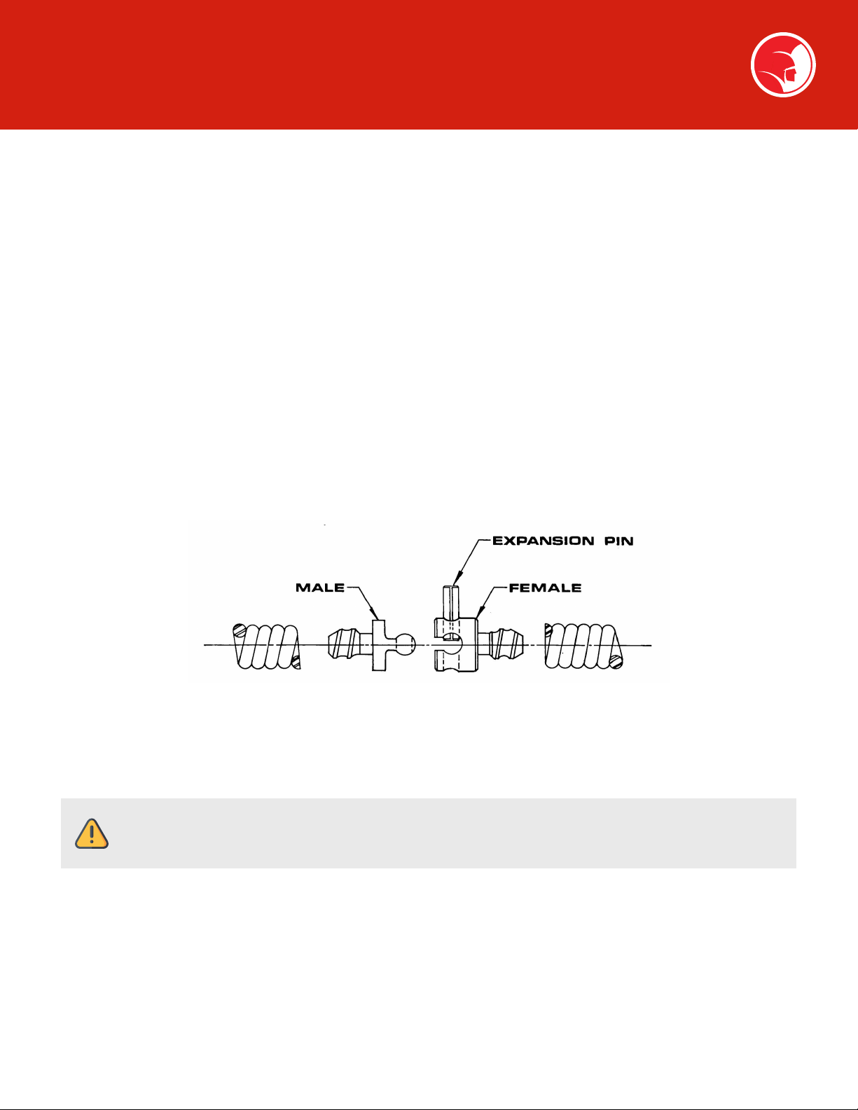
All cables and leaders are coupled together by male and female couplings, and held securely by means of expansion pins as illustrated.
The cable and coupling stand is furnished with the optional tool box to provide a support on which to rest your able when assembling
or disassembling the couplings.
Assembly
Place coupling in groove on top of stand with portion of expansion pin in upright position. Using hammer, drive expansion pin down
flush with coupling. Assembly is complete, cable and machine are ready for use.
Disassembly
Position coupling stand at convenient distance from machine (2-3 feet.) Place coupling in groove, expansion pin up, on top of stand.
Place tip of punch (provided with machine) in expansion pin. Drive expansion pin down with hammer. Note the shoulder on tip of
punch, acts as a stop. Drive the punch until shoulder is flush with the coupling. This is sufficient to permit the male and female portions
of the coupling to be separated but leaves the expansion pin, held securely in one half of the female coupling, in ready position for
reassembly.
LOADING CABLE INTO MACHINE
After uncoiling the cable and laying out flat, attach the male end of the cable to the female end of the 10' anchor in the drum. With
the machine plugged in, depress the foot actuator and check the rotation of the drum. The drum should rotate in a counter-clockwise
direction, as you face the front of the machine. If the drum rotates in the wrong direction, reverse the toggle switch located (refer to
Figure 2) on the motor support and check rotation again. With the drum rotating in the proper direction, start feeding the cable into the
drum.
FIG. 3
WARNING: Due to the amount of initial tension wound into your Spartan cable, care must be taken when
uncoiling the bundle of cable. The cable will spring apart after the wire ties, which secure the cable, are cut.

12
Assembly Instructions
Leave about 2-3 feet of cable out of the machine to allow for attaching the next section of cable. After loading your desired length of
cable, attach either a two foot leader cable or a double male coupling. You are now ready to attach your Spartan cutter blade assembly.
(See Figures 4 & 5 for Cable Connection Diagram).
CAUTION: Always wear your riveted Spartan gloves when handling a rotating cable. Read the section “How
to Operate the Power Cable Feed” before you begin to feed cable into the drum. Feed the cable into the drum
with the drum rotating. This insures proper distribution of cable inside the drum.
FIG. 4
5/8 CABLE
FIG. 5
.55 MAGNUM CABLE

13
ASSEMBLY OF BLADES TO CABLE
Assembly Instructions
Each U-Type Cutting Assembly consists of:
WARNING: Always disconnect power cord before attaching or changing blades.
FIG. 6
Each Three-Blade Cutting Assembly consists of:
FIG. 7
Blades
The optional tool box is furnished with a number of different sizes and shapes of blades for various size sewers and types of cleaning
work. (Additional tools are listed on page 14.)
Your Spartan blades can be attached to either a 2’ leader cable or a double male coupling. To attach a cutter assembly the base of the
blade holder assembly needs to be seated onto the hex part of the leader or double male coupling. Next, the proper blade size is placed
into the blade holder base. After inserting the blade, secure with blade retainer, lock washer and nut. Draw up all blades assemblies
tightly with your T-wrench, otherwise vibrating may cause unnecessary loss of blades. A T-wrench is furnished so you can quickly and
conveniently assemble blades. With the blade assembly attached, your now ready to operate your Spartan machine.`

14
Assembly Instructions
OPTIONAL TOOLS
Part Number Description Use
44006700 Extra Heavy Razor Sharp 2½" Round
Cutter Blade
Used to cut roots and clear blockages in 3", 4", and
6" lines. High water resistance
44052600 Boring Tool Used in 3", 4", and 6" linesfor penetrating major
blockages.
03416600 3" Grease Blade
For cleaning grease or muck lines. Integral
"paddles" act as a scoop and cause a churning
action within the line for quicker, more efficient
cleaning.
03416700 4" Grease Blade
For cleaning grease or muck lines. Integral
"paddles" act as a scoop and cause a churning
action within the line for quicker, more efficient
cleaning.
OPTIONAL ACCESSORIES
Tool box and the following accessories:
• Cable uncoupling stand
• Punch for expansion pin
• T wrench
• 3" and 3½" P-trap blades with blade holder assembly
• Spear blade
• 2" and 2½" blades with blade holder assembly
• 3", 4" blades with blade holder assembly
• Retriever
• Riveted gloves
• Expansion pins, double male, male and female
couplings
• Splicer
• 2' flexible leader

15
Operation
1. Couple the leader or double male coupling, complete with the proper tool, onto working end of the cable. See assembly
instructions.
2. Use a small blade or spear blade on the end of your cable first. Most lateral lines are 4”to 6”in diameter. It is advisable to use a 3”
blade or spear blade first. That enables you to cut the core out of the obstruction, to get the water running. Then remove the 3”
blade, or spear blade. Put on a blade the size of the sewer line to be cleaned, so you can actually scrape the line - thereby giving a
thorough, efficient cleaning job.
a. A good rule of thumb is to use a tool at least 1”smaller than the line to be cleaned. The style of tool is determined by the nature
of job and is left to the discretion of the operator.
b. Flexible trap leaders should be used to negotiate p-traps and severe bends in line.
c. Double male couplings should be used when operating in heavy root build up or severe obstructions.
3. Place your machine as close to the cleanout as possible. Do not allow more than 4 feet of cable between the machine and the
cleanout. Always use the Cable Safety Guide.
WARNING: Never wear loose fitting clothing or jewelry when operating this machine. Always wear your
Spartan riveted gloves when handling cable.
4. Place foot switch, in a comfortable and accessible position in order to have power at all times.
5. Place the switch in the“F” (forward) position. Check by pressing down on footswitch making sure that drum rotates in counter
clockwise direction as you face the drum.
a. Hand-feed the tool into the opening of the line and feed about 6”of cable in before turning machine on.
b. Refer to the section “How to Operate the Power Cable Feed” before proceeding.
6. Exert sufficient downward pressure on the Cable Safety Guide to keep cable in line while depressing foot actuator to start cable
rotating.
a. When using a Dial-A-Cable Power Cable Feed, keep one hand on the Cable Safety Guide halfway between the cleanout and the
power feed outlet. Keep your other hand on the power feed control handle.
7. When your blade meets an obstruction, it will no doubt fail to rotate. A reduction in RPM will be noticed. If RPM of the motor and
drum decrease, quickly pull back on the cable to disengage blade from the root or other obstructions. Thereby releasing torque or
tension on your cable—preventing buckling or kinking of cable.
WARNING: Operator should be thoroughly familiar with the Safety Instructions section before attempting
to operate this equipment.
WARNING: Do not permit blade end to get hung up in an obstruction for more than 2 to 3 seconds. Your
job as an operator of this machine is to keep the cable rotating. Remember, do not operate the machine to the
point where the cable begins to buckle. This practice is dangerous and could damage the cable.

16
Operation
NOTE: Kinkage and breakage of cable is caused solely by one thing: you permit the working end of the
cable to get hung up in an obstruction and you keep on twisting the other end of same with your motor, until
something must give. Remember, the only way you can clean an obstruction from a line, or negotiate a bend
in a line, is when your blades are rotating. Let us repeat: your job is to keep the blades rotating. The design of
your motor is such that as soon as the blade end of your cable gets hung up in an obstruction, your motor RPM
reduces. That reduction in speed is notice to the operator to pull the blade away from the obstruction, thereby
releasing the tension that has been built up in the coil-spring cable. That release of tension prevents buckling,
kinking or breakage of the cable.
8. A good rule to follow for releasing tension on a cable is this: when your blade gets hung up in the obstruction and fails to rotate,
an RPM reduction will be noticeable which indicates it is time to pull the blade away from the obstruction. As you pull it away, all
tension in the cable will be released immediately and your blades will turn at a high speed. As soon as the blade is free, push it back
into the obstruction quickly so as to utilize the built-up power which enables you to clean the line more quickly and efficiently.
WARNING: Do not allow a tool to get hung up in an obstruction. If a tool gets hung up in an obstruction,
a reverse feature is provided on this machine for just this purpose. In the event your blade gets hung up on
an obstruction and you are unable to release it in the normal manner, move the toggle switch to the“OFF”
position, and permit your machine to come to a dead stop. Then, move the toggle switch in the“R”(reverse)
position. Now start your machine slowly. See if you can remove the blade from the root or other obstruction
by this reverse action. When the blade is released, let your machine come to a dead stop again. Then place the
toggle switch in the“F” (forward) position. Make sure that the cable/blade rotates counter clockwise, when
standing in front of the machine, except when reversing it to free cutting tool from obstruction.
WARNING: Do not reverse machine until motor and drum come to a dead stop.
Avoid operating this machine in reverse for any other purpose.
9. When you cut through one group of roots, it is always good to pull back your cable and take another cut. This final cut is what gives
you a thorough cleaning job.
10. When the job is complete, feed the cable back into drum, making sure that your machine is running, so that the distributor arm can
feed and distribute cable in the drum properly.
• KEEP MACHINE RUNNING in the forward direction.
WARNING: Never retract tool from sewer inlet while cable is rotating.
NOTE: It is recommended that a continuous flush of water can be used to clean cable and tool as they
are retrieved.

17
Operation
11. When tool is close to the clean out opening, release foot actuator and allow machine to come to a complete stop.
12. Move toggle switch to the “OFF”position and disconnect machine from power source.
13. Pull remaining cable and tool from the line and hand-feed cable back into the drum.
Operating the Power Cable Feed
1. The adjusting knob on the top controls the tension on the cable. It should be set so that the cable feeds freely in-and-out of the
drum. Tension can be increased by turning handle to the right. Don’t apply too much tension—just enough to keep the cable
moving is sufficient.
2. Cable is fed into the line by putting the handle in forward position. This speed will vary from 0-30 feet per minute depending on
size of the cable and how far forward you push the handle.
3. Cable is brought out of the line by putting the handle in reverse position. You can also vary the speed in reverse.
4. When the handle is straight up, the drive is in neutral position. There is no lateral movement of cable at this point. This enables the
operator to position the blade against the stoppage and chew it away if necessary.
5. Another feature of the Dial-A-Cable Power Cable Feed is its ability to change from FORWARD to REVERSE by simply moving the
handle. The feed reacts immediately.
6. New drive design permits repair right in the field. Entire unit can be taken apart and put back in working order in just ten minutes.
WARNING: (1) Never try to force the cable into the line. Choose a proper feeding speed that gives a smooth
cutting action. (2) Refer to operating and maintenance instructions for proper maintenance.

18
Special Applications Procedure
CLEANING LINES THROUGH A MANHOLE
1. Position your machine at top and about 1' away from manhole.
2. Use a length of 1½" pipe with 45° elbow screwed there to (the depth of the manhole determines the proper length of pipe to be
used).
3. Hand-feed your cable, less leader and blade, through proper length of 1½" pipe.
4. Fasten leader or double male coupling with proper size blade to end of cable.
5. Place blade into line by the use of extension pipe. The length of pipe referred to povides a guide for your flexible shaft from the top
of the manhole to the entrance of the line, thereby preventing your cable from buckling or kinking. It likewise enables the operator
to operate the machine in a convenient, comfortable position at the top of the manhole. Never enter the manhole.
RODDING FARTHER THAN 75' (5/8" CABLE*)
The object of the 5' anchor cable is in the drum is this: When you have fed 75' of cable into the line, the female coupling on the end of
the 5' piece will show up at the end of the distributor arm on your machine. You will then know that you have 75' of cable in the line.
Now, let’s suppose that the line you are cleaning requires more than 75'of cable.
This is the procedure to follow:
1. Disconnect the 75' of cable and leave it in the line. Insure that it cannot fall into the pipe beyond the opening.
2. Take the male end of your extension and add it to the 5' piece in the drum, feeding the whole extension piece into the drum.
• NOTE: The machine should be operating in the forward direction.
3. Hook up to the 75' piece in the sewer and resume rodding.
• *NOTE: 100' of .55 magnum cable can fit in the drum at one time.
MAIN SEWER OR SEPTIC TANK OVERRUN
It is very important to know the approximate distance from inlet to main sewer or septic tank. Overrunning cable too far into main
sewer or septic tank can allow cables to knot up and prevent their retrieval.

19
Maintenance Instructions
WARNING: Make sure machine is unplugged from the electrical system before making any adjustment.
INSTRUCTIONS FOR SPLICING OR REPAIRING CABLE
Splicing Cable (Standard Single Wound Cable)
1. Square ends of cable to be spliced or repaired by placing each end against a grinding wheel, grinding down so that the shoulder of
splicer or coupling will butt squarely against the cable ends. (If splicing “INNER-CORE CABLE”, and inner-core protrudes from cable at
point of repair, pull the inner-core out of the cable just far enough to allow for the insertion of the connector. Then cut the inner-
core off and push back into cable.)
2. Put cable in vice and open ends slightly with drive punch so that opening is just large enough to allow connector to be inserted.
3. Clean splicer or coupling of rust or grease.
4. Connect cables to splicer, or coupling and draw uptightly to shoulder of connector, as illustrated above.
5. Put cable in vice and open ends slightly with drive punch so that opening is just large enough to allow connector to be inserted.
Splicing the .55 Magnum Cable and Installing New .55 Couplings
FIG. 8
Item Part Number Description
1 44110400 .55 Long Male Coupling
2 44110500 .55 Female Coupling
3 44114500 .55 Splicer
4 44111300 .55 Male Coupling
or 44114300 .55 Leader Male Coupling
5 44291601 Anchor Adapter .55 to ⁄"
NOTE: Couplings and splicer
for the .55 Magnum Cable are not
interchangeable with ½" or ⁄"
Spartan cable connectors.

20
Maintenance Instructions
1. Grind cable square by placing the cable end against a grinding wheel. Care is to be taken to assure the innercore is flush with outer
cable. Grind outer cable and innercore down enough to produce a flat contact surface between the cable and connector (splicer or
coupling).
2. Secure the cable into a vise, making sure innercore remains flush with outer cable.
3. Clean connector and inside of cable from rust or dirt. (Care to be taken on cleaning connector threads.) Also it may be necessary to
deburr inside of cable.
4. Insert connector into innercore in the manner of tightening a right hand threaded screw. Tighten connector enough so that contact
is made between outer cable and the connector face. If required, step two through four should be repeated for the other cable end.
5. Since the coupling and the wire in the cable are of high carbon steel, a special welding process is required. Before welding, use a
propane torch to preheat the area where the weld will be. Hold the torch 4-5" away from the metal surface and heat for 2 minutes.
Immediately, weld with an arc welder, using 3/32" diameter unit rod #70 or equivalent chromium-stainless steel rod. Use a heat
range of 90-100 amps. Be sure weld bead is 1/8”wide and 1/2” long, where each wire end contacts the coupling.
After welding, it will be necessary to stress relieve the welded area. Again, using a propane torch holding 4-5”away from metal
surface, heat up to approximately 5 minutes. Allow to cool and cable will be ready for use.
FIG. 9 FIG. 10
NOTE: Never heat the cable to a cherry red color. This indicates too high a temperature and will weaken
the cable.
Table of contents
Other Spartan Cleaning Equipment manuals


