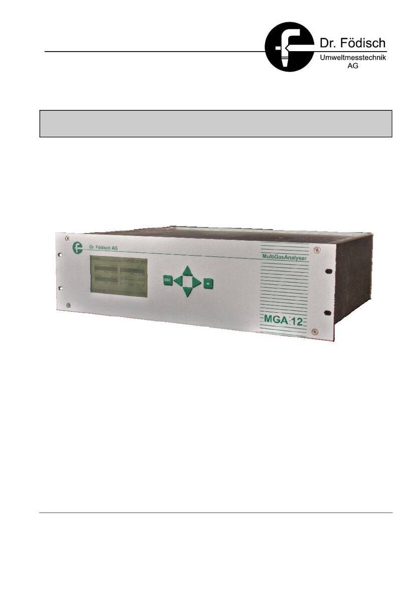
Dr.Fodisch MCA 10 HWIR User manual

Multi Component Analyser
MCA 10 HWIR
Operation Manual

Dr. Födisch Umweltmesstechnik AG
Zwenkauer Strasse 159
04420 Markranstädt
Germany
Phone: +49 34205 755-0
Fax: +49 34205 755-40
Internet: www.foedisch.de
Version/date of operation manual: Version 3.3, 14.09.2021
© Dr. Födisch Umweltmesstechnik AG
This operation manual is not subject to the service of change. Distribution and duplication of the
operation manual and all related documents as well as use and communication of its content are
forbidden unless it has not been permitted explicitly in written way by Dr. Födisch Umweltmesstechnik
AG. Any violation obliges to compensate the loss.
All rights are reserved for the case of a registration of a patent, utility patent or design patent.

Content
Version 3.3
Operation Manual MCA 10 HWIR
3
Content
1General .......................................................................................................................................6
1.1 Information for operation manual ................................................................................................6
1.2 Intended use................................................................................................................................6
1.3 Warranty......................................................................................................................................7
1.4 Standards and regulations...........................................................................................................7
1.5 Declaration of conformity.............................................................................................................7
2Safety..........................................................................................................................................8
2.1 Safety instructions.......................................................................................................................8
2.1.1 General safety instructions..........................................................................................................8
2.1.2 Specific safety instructions..........................................................................................................9
2.1.3 Personal protective equipment..................................................................................................10
2.2 Requirements for personnel......................................................................................................11
2.3 Electrical power supply..............................................................................................................12
2.4 Gas supply.................................................................................................................................14
2.5 Components ..............................................................................................................................15
2.6 Electronic elements...................................................................................................................15
2.7 Configuration settings................................................................................................................15
3Basics.......................................................................................................................................16
3.1 Photometry ................................................................................................................................16
3.1.1 Bi-frequency measuring method ...............................................................................................17
3.1.2 Gas filter correlation ..................................................................................................................18
3.1.3 Oxygen measurement...............................................................................................................19
3.2 Compensation of measuring components.................................................................................20
4Functional description............................................................................................................21
5Design.......................................................................................................................................23
5.1 Emitter unit.................................................................................................................................24
5.2 Cuvette ......................................................................................................................................25
5.3 Detector unit..............................................................................................................................26
5.4 Gas distribution block................................................................................................................27
5.5 Pressure and flow measurement...............................................................................................27
5.6 Oxygen sensor (optional)..........................................................................................................27
5.7 Mainboard..................................................................................................................................28
5.8 Power supply unit......................................................................................................................29
5.9 Interfaces...................................................................................................................................29
5.10 Connection assignment.............................................................................................................30
5.11 System design (application example)........................................................................................31
5.11.1 Gas circuit diagram....................................................................................................................32
5.11.2 Design of CPU components......................................................................................................34
5.11.3 Signal plan.................................................................................................................................35
6Transport and scope of supply..............................................................................................36
6.1 Transport ...................................................................................................................................36
6.2 Scope of supply.........................................................................................................................36

Content
4
Operation Manual MCA 10 HWIR
Version 3.3
7Placement and mounting....................................................................................................... 37
7.1 Placement................................................................................................................................. 37
7.2 Mounting................................................................................................................................... 37
7.3 Placement and mounting of additional devices........................................................................ 37
8Commissioning....................................................................................................................... 38
8.1 Commissioning of MCA 10 HWIR............................................................................................. 38
8.2 Test gas provision..................................................................................................................... 39
8.3 Software installation.................................................................................................................. 40
9Operating................................................................................................................................. 41
9.1 Display and operating elements............................................................................................... 42
9.1.1 General screen design.............................................................................................................. 42
9.1.2 Display and operating elements within menus......................................................................... 43
9.1.3 Display “data transfer” .............................................................................................................. 45
9.2 Menu structure.......................................................................................................................... 46
9.3 Password levels........................................................................................................................ 49
9.4 Main menu................................................................................................................................ 50
9.4.1 Change language...................................................................................................................... 51
9.4.2 Input password.......................................................................................................................... 51
9.5 Measurement............................................................................................................................ 52
9.6 System control.......................................................................................................................... 54
9.7 Diagnostics ............................................................................................................................... 55
9.8 Messages.................................................................................................................................. 56
9.9 Auto calibration......................................................................................................................... 58
9.10 Calibration................................................................................................................................. 59
9.11 Configuration............................................................................................................................. 62
9.12 Service mode............................................................................................................................ 64
10 Maintenance/Upkeep.............................................................................................................. 65
10.1 Exchange injector screwing-in.................................................................................................. 66
10.2 Exchange sinter metal filter of cuvette / exchange gaskets at cuvette inlet block.................... 66
10.3 Exchange screwing-in with nozzle at gas distribution block..................................................... 67
11 Error search and failure clearance........................................................................................ 68
11.1 Service qualification of the specialised personnel.................................................................... 68
11.2 Displaying of current messages and clearing of failures.......................................................... 69
11.2.1 Messages “failure” .................................................................................................................... 70
11.2.2 Messages “maintenance” ......................................................................................................... 79
11.2.3 Messages “maint. req.”............................................................................................................. 81
11.2.4 Info message ............................................................................................................................ 88
12 Shutdown and Disposal......................................................................................................... 89
12.1 Shutdown.................................................................................................................................. 89
12.2 Disassembling........................................................................................................................... 90
12.3 Storage ..................................................................................................................................... 90
12.4 Disposal.................................................................................................................................... 90
13 Technical data......................................................................................................................... 91
13.1 Multi component analyser MCA 10 HWIR................................................................................ 91
13.2 Measuring ranges of MCA 10 HWIR ........................................................................................ 93
14 Spare and wear parts ............................................................................................................. 94

Content
Version 3.3
Operation Manual MCA 10 HWIR
5
15 System application with analyser cabinet............................................................................97
15.1 Design of analyser cabinet........................................................................................................97
15.2 Transport of analyser cabinet....................................................................................................98
15.3 Placement and Mounting...........................................................................................................99
15.3.1 Placement..................................................................................................................................99
15.3.2 Mounting..................................................................................................................................100
15.4 Commissioning........................................................................................................................101
15.5 Automatic zero point setting via “Thermocal”..........................................................................102
15.6 Test gas provision ...................................................................................................................103
15.6.1 Local test gas provision at MCA 10 HWIR..............................................................................104
15.6.2 Test gas provision via gas sample probe (optional)................................................................104
15.7 Maintenance/Upkeep...............................................................................................................106
15.8 Error search and failure clearance..........................................................................................106
15.9 Shutdown and disposal ...........................................................................................................107
15.9.1 Shutdown.................................................................................................................................107
15.9.2 Disassembling.........................................................................................................................108
15.9.3 Storage....................................................................................................................................108
15.9.4 Disposal...................................................................................................................................108
15.10 Technical data.........................................................................................................................109
15.11 Spare and wear parts..............................................................................................................110
16 Index .......................................................................................................................................112

1General
6
Operation Manual MCA 10 HWIR
Version 3.3
1 General
1.1 Information for operation manual
This operation manual contains the required information for intended use of the described
product. It is firm part of the scope of supply, also if the possibility of separated order
respectively delivery had been planned due to logistic reasons. By reasons of clarity it does
not contain all details for all types of the described product and it cannot consider each
possible case in operation with the product.
Read the operation manual completely and attentively. Observe the safety instructions and
operation directions in this operation manual as well as the labelling at the device and the
packaging. For later use keep the operation manual at a safe place.
If you should need further information or if problems should occur which are not described
elaborately in this operation manual, please refer to Dr. Födisch Umweltmesstechnik AG
(contact details: see cover inside).
For operation with the optional additional devices please read the technical documentations of
the suppliers (see appendix). The contents are at responsibility of the respective
manufacturers.
1.2 Intended use
The product described in this operation manual has been developed, manufactured, tested
and documented in observation of the corresponding safety standards and has left the factory
in safety-related correct and tested condition.
By observing the actions and safety instructions described for configuring, assembly, intended
use and upkeep, there is no danger coming up by the product itself in normal case. The
correct and safe operation presupposes furthermore the proper transport, professional
storage, placement and assembly as well as careful operating and upkeep.
The multi component analyser MCA 10 HWIR serves the continuous emission measurement
of pollutants in flue gas. It is applicable all-purpose for measurement of emissions, raw gases
or processes. As system in regulatory and operational emission measurement systems it
serves the exhaust concentration control in combustion plants with different types of fuel,
thermal waste treatment, combustion optimisation or process management control.
To keep the correct condition of the device and to achieve a proper and safe operation it must
solely be used in the way described by the manufacturer. Any kind of differing use as
described in this operation manual is regarded as non-intended use and can result in personal
or material damage.
Non-intended use results in termination of guarantee.

1General
Version 3.3
Operation Manual MCA 10 HWIR
7
1.3 Warranty
The Dr. Födisch Umweltmesstechnik AG advises that the content of this operation manual is
not part of a prior or present arrangement, commitment or legal relationship or that does not
change these. All liabilities result from the respective sales contract which also contains the
complete and solely legal warranty regulations. These contractual warranty terms are neither
extended nor limited by the contents in this operation manual.
Rebuilding and modification at the product is not permitted. Any intervention into the device as
well as any kind of non-intended use results in termination of guarantee. The manufacturer
assumes no liability at all.
1.4 Standards and regulations
As far as possible, the harmonised European standards have been applied to specification
and production of this device. If no harmonised European standards have been applied, the
standards and regulations for the Federal Republic of Germany apply.
1.5 Declaration of conformity
The multi component analyser MCA 10 HWIR has a CE label. Therewith we declare that the
device in its conception and design as well as in the execution put into circulation by us
corresponds to the fundamental safety and health requirements.
NOTICE
On request the document of conformity declaration is placed at the disposal by
Dr. Födisch Umweltmesstechnik AG (contact details: see cover inside).

2Safety
8
Operation Manual MCA 10 HWIR
Version 3.3
2 Safety
The device must solely be operated in correct condition and in strict observation of the safety
instructions.
Working at the device must solely be executed by qualified specialised personnel
(see section 2.2 “Requirements for personnel”, page 11). Personal protective equipment
according to the current legal accident prevention regulations must be worn.
Please read the safety instructions for the optional additional devices in the technical
documentations of the suppliers (see appendix). The contents are at responsibility of the
respective manufacturers.
2.1 Safety instructions
Safety instructions serve the prevention of hazards for life and health of users or upkeep
personnel respectively for avoiding material damage. In this operation manual they are
emphasised by the here defined signal terms. Furthermore, special safety instructions can be
characterised by additional symbols.
2.1.1 General safety instructions
DANGER
Notes with signal word “DANGER” indicate possible hazards which cause personal
damage in terms of death or most serious injury in case of non-observing the safety
precautions.
WARNING
Notes with signal word “WARNING” indicate possible hazards which cause personal
damage in terms of simple up to serious injury in case of non-observing the safety
precautions.
CAUTION
Notes with signal word “CAUTION” indicate possible hazards which cause material
damage in case of non-observing the safety precautions.
NOTICE
Notes with this indication describe helpful information and tips for operation with the
product and serve the avoidance of failure.

2Safety
Version 3.3
Operation Manual MCA 10 HWIR
9
2.1.2 Specific safety instructions
DANGER
Hazardous voltage!
Parts of the device can be energised with hazardous voltage.
Danger of electric shock.
Any work at the device must solely be executed by qualified personnel.
DANGER
Explosion hazard!
Personal damage in immediate surround as well as material damage at the device and
its vicinity can be caused.
The device must not be operated in potentially explosive atmosphere.
DANGER
Poisonous substances!
Poisonous gases can cause serious health damage or death.
Irritating of eyes, skin or respiratory system organs can be caused.
Exhaust of the gas output must be conducted into an exhaust system.
The correct operation of ventilation in the analyser cabinet must be assured.
WARNING
Corrosive substances!
Irritating or corrosive gases or substances can cause chemical burn of body tissue and
serious eye injury in case of contact.
In case of contact with skin or eyes the affected spots must be cleaned immediately!
Objects which have been contacted with irritating or corrosive gases or substances must
be cleaned accurately.
WARNING
Hot surface!
Several device parts can develop high temperatures.
Burn of skin can be caused!
For protection against possible injury protective gloves must be worn.

2Safety
10
Operation Manual MCA 10 HWIR
Version 3.3
2.1.3 Personal protective equipment
WEAR PROTECTIVE CLOTHING
For protection against injury at any kind of hazard protective clothing must be worn.
WEAR PROTECTIVE FOOTWEAR
For protection against possible injury protective footwear (e.g. safety shoes) must be
worn.
WEAR PROTECTIVE GLOVES
For protection against possible injury at touching of device components protective gloves
must be worn.
WEAR HEAD PROTECTION
For protection against possible injury by falling objects or bouncing hazard a head
protection must be worn.
WEAR RESPIRATORY PROTECTION
For protection against possible suffocation hazard or injury of respiratory system organs
by poisonous gases a respiratory protection must be worn.
WEAR EYE PROTECTION
For protection against possible eye irritation by corrosive gases or substances eye
protection must be worn.
WEAR HEARING PROTECTION
For protection against possible hearing impairment by high noise level hearing protection
must be worn.

2Safety
Version 3.3
Operation Manual MCA 10 HWIR
11
2.2 Requirements for personnel
This operation manual is directed to technically qualified personnel which have been specially
instructed or which possesses appropriate knowledge in the field of measuring, control and
feedback control technology, called automation technology further on.
Qualified personnel are persons who
are either familiar as configuring personnel with the safety concepts of automation
technology
or are instructed as operating personnel in operation with automation technology equipment
and are acquainted with the contents of these instructions referring to operation
or have been instructed as commissioning and/or service personnel to be qualified for
repair of such automation technology equipment respectively who are authorised to
energise, ground and tag circuits and devices/systems according to the standards of safety
engineering.
The knowledge and the technically correct realisation of the safety instructions and operating
directions described in this operation manual are the requirement for hazard-free assembly
and commissioning as well as for safety at operation and upkeep. The specialised personnel
must be familiar with the general risks and hazards and know and observe the respective
safety precautions.
Unqualified interventions into the device or non-observance of the operation manual or of the
affixed labels on the product can result in personal or material damage.
Any work at the device must solely be executed by qualified specialised personnel in
observation of the corresponding regulations (central association of electrical engineering and
industry).

2Safety
12
Operation Manual MCA 10 HWIR
Version 3.3
2.3 Electrical power supply
DANGER
Hazardous voltage! Danger of electric shock.
Also when the device is switched off, there can be high voltage inside it.
Any work at the device must solely be executed by qualified personnel. The following
requirements must be observed.
Insulation: protection class I according to IEC 1010-1:1993
Insulation co-ordination: overvoltage category II according to IEC 1010-1:1993
Pollution: safe work of device in an area up to pollution degree 2 according to
IEC 1010-1:1993 (light, normal pollution which can become conductive by occasional
condensation)
The power supply has to be installed and secured according to the corresponding legal
safety regulations and prescriptions.
The device must only be connected to the supply voltage designated on the type plate.
A protective separation between primary and secondary circuit is generally ensured. Low
voltage which is connected must also be generated by protective separation.
Grounding contact:
- The device must always be grounded. It has only to be operated at a power supply with
grounding contact.
- The grounding conductors in the device or the feeder must not be separated or removed.
- The protection effect must not be abolished by an extension without grounding conductor.
Every kind of interruption of the grounding conductor inside or outside of the device is
hazardous and not permitted.
- In the case of insufficient grounding or damaged grounding conductor the device must be
shut down and secured against unauthorised or inadvertent activation.
Fuses:
- In the case of a required fuse change, only fuses must be used which are according to
the old fuses in type and capacity.
- Auxiliary fuses must not be used.
- Fuse holders must not be shorted.
Cables must be laid that an accident risk by tripping or getting caught is excluded.
Covers:
- The device must not be operated when covers or other parts have been removed,
because current carrying parts are divested of covering in operation.
- If not explicitly requested, work inside the device must not be executed.
- Before opening the device it must be de-energised by exerting the pre-fuse.
- If work at the opened device is necessary (adjustment, maintenance etc.), this work must
only be executed by appropriate qualified personnel which is familiar with the hazard
points and which has knowledge of avoiding hazards by proper safety precaution.

2Safety
Version 3.3
Operation Manual MCA 10 HWIR
13
Electrical safety
If the electrical safety of the device is not given anymore, the device must be shut down and
secured against unauthorised or inadvertent activation.
The electrical safety of the device is not given any more if it:
has visible external damage
does not work correctly anymore
has been stored under impermissible or inappropriate conditions for any length of time
has been encountered impermissible strain during transport

2Safety
14
Operation Manual MCA 10 HWIR
Version 3.3
2.4 Gas supply
DANGER
Explosion hazard!
Personal damage in immediate surround as well as material damage at the device and
its vicinity can be caused.
The device must not be operated in potentially explosive atmosphere.
Observe the safety instructions of the gas supplier.
DANGER
Poisonous substances!
Vapours and gases escaping from the cuvette are poisonous. Filters from cuvette, gas
sample probe and pump can contain poisonous substances. Also leakage inside the
analyser cabinet results in accumulation of poisonous or corrosive gases.
Serious health damage (e.g. irritation of eyes, skin or respiratory system organs) or death
can be caused.
Exhaust of the gas output must be conducted into an exhaust system.
The correct operation of ventilation in the analyser cabinet must be assured.
Observe the safety instructions of the gas supplier.
WARNING
Corrosive substances!
Depending on the measuring gas incidental substances can be corrosive and/or
poisonous.
Contact can cause chemical burn of body tissue and serious eye injury.
In case of contact with skin or eyes the affected spots must be cleaned immediately!
Objects which have been contacted with irritating or corrosive gases or substances must
be cleaned accurately.
The compressed-gas cylinders and equipment (gas bottles, valves, pipes, pressure reducer
etc.) must be installed and operated according to the corresponding legal safety regulations
and prescriptions.
In the bottle room and near of compressed-gas cylinders naked light, fire, smoking and
sparking are forbidden.
Compressed-gas cylinders:
- All compressed-gas cylinders must be positioned upright into steady mounted holders
and secured against toppling by chains or rods.
- The compressed-gas cylinders, theirs content and all continuative gas pipes must be
designated clearly.
- In case of storage in closed rooms sufficient ventilation must be ensured.
- The compressed-gas cylinders must be kept away from heat sources and protected
against direct solar radiation and temperature fluctuation.
For every kind of gas solely the respective permissible pressure reducer must be used.
Pressure gas hoses must be laid that an accident risk by tripping or getting caught is
excluded. Likewise they must be protected against damage caused by falling objects and
treading on.
In case of standstill for any length of time the bleeder valves of the compressed-gas
cylinders respectively of gas supply must be closed, the pressure inside the gas pipes to
the device must be released and all valves must be closed.

2Safety
Version 3.3
Operation Manual MCA 10 HWIR
15
2.5 Components
The device as well as the single components must only be operated as original variant. In
case of exchanging single elements only the original parts of the manufacturer must be used.
Components are configured device-specific and hence they are not interchangeable between
different devices.
2.6 Electronic elements
Electrostatic discharges can cause damage at the electronic elements. The following
precautions must be taken:
Electronic elements must be stored in the original packaging directly until use.
Electronic elements must be touched at housing. The contacts must not be touched.
Electronic elements and conductor plates must be kept away from statically charged
surfaces (PVC plastics, plastic bags etc.).
Wear a special ESD wrist band or use a grounded, antistatic working surface.
2.7 Configuration settings
Changes of configuration can endanger the safety and function of the device. Configuration
settings must solely be executed by an authorised service technician or by factory personnel
of the manufacturer.

3Basics
16
Operation Manual MCA 10 HWIR
Version 3.3
3 Basics
3.1 Photometry
The principle of the gas component measurement is based on the substance-specific
extinction of infrared light. This is directed through the measuring gas whereat the lessening of
the light intensity within the substance-specific absorption wave length is a degree for its
concentration.
Fig. 1: Measuring technological implementation of photometry
1 Infrared emitting source
2 Aperture wheel
3 Comparison cuvette
4 Gas detector
5 Amplifier
6 Indicator
7 Test gas outlet
8 Measuring cuvette
9 Test gas inlet
The physical basis for photometric measurement is the Lambert-Beer’s law.
E Extinction
l0Intensity of emitted light
l Intensity of received light
e Extinctions coefficient
c Concentration of the measured component
d Transmitted wave length
For calculation of gas concentrations in the MCA 10 HWIR three different measuring methods
are applied:
Bi-frequency measuring method
Gas filter correlation
Oxygen measurement
3
2
1
4
5
6
9
7
8

3Basics
Version 3.3
Operation Manual MCA 10 HWIR
17
3.1.1 Bi-frequency measuring method
At bi-frequency measuring method a measuring filter and subsequently a reference filter are
directed into the light path. Thereby the transmission range of the measuring filter lies in the
range of the absorption wave length of the measuring component. The transmission range of
the reference filter lies in the spectral range outside of the absorption wave length of the
measuring component. So the light intensities with and without gas influence can be
determined successively.
Measurement of: NO2, SO2, HF, H2O, CO2
Fig. 2: Bi-frequency measuring method –scheme
1 Measuring filter
2 Receiver
3 Reference filter
4 Measuring cell (cuvette)
5 Light source
Fig. 3: Bi-frequency measuring method –spectrum
1 SO2 band
2 Reference filter
3 Measuring filter
1
4
5
2
3
Wave number [cm-1]
Transmission [%]
1
2
3

3Basics
18
Operation Manual MCA 10 HWIR
Version 3.3
3.1.2 Gas filter correlation
At gas filter correlation the spectral sphere of action of the reference filter is identical with the
one of the measuring gas filter. The reference filter position possesses an additional gas filter
which is filled with a high concentration of the gas to be measured in order to reach the
saturation of the infrared absorption. Thereby the substance-specific spectrum of the infrared
light is almost completely faded out.
Measurement of: CO, NO, HCl, NH3, N2O, CH4
Fig. 4: Gas filter correlation –scheme
1 Gas filter
2 Interference filter
3 Receiver
4 Free aperture
5 Measuring cell (cuvette)
6 Light source
Fig. 5: Gas filter correlation –spectrum
1 HCl band
2 Interference filter
1
5
2
4
3
6
Transmission [%]
Wave number [cm-1]
1
2

3Basics
Version 3.3
Operation Manual MCA 10 HWIR
19
3.1.3 Oxygen measurement
The oxygen measurement is carried out by means of a zirconium dioxide cell. Inside the cell
the measuring gas is separated from the reference gas (ambient air) via a zirconium
membrane. Depending on the oxygen partial pressure the oxygen ions move through the
membrane. This results in an electric potential difference.
The used oxygen sensor consists of a measuring cell and a pump cell which provides a
constant oxygen concentration in the measuring cell. The thereby spent energy is a degree for
the oxygen concentration.
Due to the proven proportionality of the signal to the concentration a steady exactness in all
oxygen concentration ranges is ensured.
Fig. 6: Oxygen measurement –functional principle
1 Exhaust
2 Pump cell
3 Measuring cell
4 Reference medium
5 Heater
1
2
3
4
5

3Basics
20
Operation Manual MCA 10 HWIR
Version 3.3
3.2 Compensation of measuring components
The following table shows the cross sensitivities of the single measuring components in
correlation. In case of an existing cross sensitivity compensation is required.
Cross sensitivity component
HF*
CO2
HCl
H2O
CH4
CO
NO2
SO2
N2O
NO
NH3
O2
TOC
Measuring component
HF*
-
CO2
-
HCl
-
H2O
-
CH4
-
CO
-
NO2
-
SO2
-
N2O
-
NO
-
NH3
-
O2
-
TOC
-
compensation required
*
not suitability tested according to DIN EN 15267‑3; certified in compliance with MCERTS
Performance Standards
Tab. 1: Compensation table
Table of contents
Other Dr.Fodisch Measuring Instrument manuals
Popular Measuring Instrument manuals by other brands

Pelstar
Pelstar Health o meter Professional PORTROD User instructions

Kane
Kane 9206 Quintox user manual

Agilent Technologies
Agilent Technologies 8712ET User's Handbook Supplement

Lutron Electronics
Lutron Electronics DW-6093 Operation manual

ECOWITT
ECOWITT WH0291 instruction manual

Izzo
Izzo SWAMI LZ-i manual