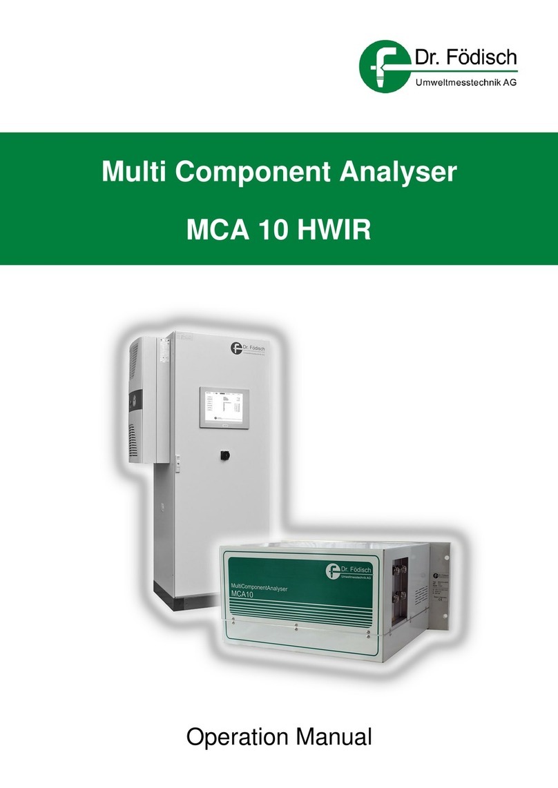
Dr.Fodisch MGA 12 User manual

MultiGasAnalyser MGA 12
Operation manual
Dr. Födisch Umweltmesstechnik AG telephone: +49-34205-755-0
Zwenkauer Strasse 159 fax: +49-34205-755-40
internet: www.foedisch.de

Dr. Födisch
Umweltmesstechnik
A
G
Page 2 of 78 Operation manual MGA 12 Version 1.3
Dr. Födisch Umweltmesstechnik AG
Zwenkauer Strasse 159
D - 04420 Markranstädt
telephone: +49-34205-755-0
fax: +49-34205-755-40
internet: www.foedisch.de
Date of manual: 27.06.2019
File path: O:\MGA12\Dokumentation\Bedienungsanleitung\en\en.Operation manual
MGA12 1.3_os.doc
© Dr. Födisch Umweltmesstechnik AG 2009 - 2019
This manual is not subject to an updating service. The distribution as well as the reproduction of the manual
and all related documents, the utilisation and the communication of its content are prohibited if not explicitly
permitted by Dr. Födisch Umweltmesstechnik AG in written way. Violations oblige for compensation o
f
losses.
All rights for the case of registration of patent, utility patent or design patent are reserved.

Dr. Födisch
Umweltmesstechnik
A
G
Version 1.3 Operation manual MGA 12 Page 3 of 78
Content
1General remarks 8
1.1General information ...................................................................................................8
1.2Advices on using the manual.....................................................................................8
1.3Warning advices ........................................................................................................8
1.4Intended use ..............................................................................................................9
1.5Qualified personnel....................................................................................................9
1.6Warranty information ...............................................................................................10
1.7Delivery information .................................................................................................10
1.7.1Scope of supply .......................................................................................................10
1.8Standards and regulations.......................................................................................10
1.9Declaration of conformity.........................................................................................10
2Safety advices 11
2.1General remarks......................................................................................................11
3Structure and function 12
3.1Structure of analyser ...............................................................................................12
3.1.1Back side .................................................................................................................14
3.1.2Dimensions ..............................................................................................................15
3.2Function ...................................................................................................................15
3.2.1Measuring principle .................................................................................................15
4Assembly 19
4.1Installation instructions ............................................................................................19
4.2Gas conditioning......................................................................................................20
4.3Gas connections and internal gas flow sheet..........................................................21
4.4Electrical connection................................................................................................22
4.4.1–X10 Power supply..................................................................................................23
4.4.2–X20 Analogue outputs | Digital outputs (measuring ranges).................................23
4.4.3–X21 Digital outputs (status, limit values, valves) ...................................................24
4.4.4–X22 Digital inputs...................................................................................................25
4.4.5–X30 RS 232 ...........................................................................................................26
4.4.6–X31.........................................................................................................................26
5Set-up 27
5.1Safety advices .........................................................................................................27
5.2Preparations for set-up ............................................................................................27
5.3Execution of set-up ..................................................................................................28
5.4Calibration................................................................................................................29
5.4.1General remarks......................................................................................................29
5.4.2Automatic calibration ...............................................................................................30
5.4.2.1Zero point calibration ...............................................................................................30
5.4.2.2Reference point calibration......................................................................................31
6Operation and handling 32
6.1Display of the analyser ............................................................................................32
6.1.1Status line ................................................................................................................32

Dr. Födisch
Umweltmesstechnik
A
G
Page 4 of 78 Operation manual MGA 12 Version 1.3
6.1.2Measuring mode ..................................................................................................... 33
6.1.3Input mode .............................................................................................................. 33
6.2Operation ................................................................................................................ 34
6.2.1Keys ........................................................................................................................ 34
6.2.2Input ........................................................................................................................ 34
6.2.3Parameter input ...................................................................................................... 35
6.3Main menu .............................................................................................................. 36
6.3.1Setup....................................................................................................................... 36
6.3.1.1Setup | Integration................................................................................................... 37
6.3.1.2Setup | Outputs ....................................................................................................... 37
6.3.1.2.1Setup | Outputs | Output units................................................................................. 37
6.3.1.2.2Setup | Outputs | Output range ............................................................................... 38
6.3.1.2.3Setup | Outputs | Range change-over .................................................................... 39
6.3.1.2.4Setup | Outputs | Output limit values ...................................................................... 39
6.3.1.2.5Setup | Outputs | H3PO4 metering ......................................................................... 40
6.3.1.2.6Setup | Outputs | Probe back flushing (optionally).................................................. 40
6.3.1.2.7Setup | Outputs | Analogue outputs ........................................................................ 41
6.3.1.2.8Setup | Outputs | Analogue outputs | Output during AUTOCAL............................. 41
6.3.1.2.9Setup | Outputs | Analogue outputs | Output during MAINTENANCE.................... 41
6.3.1.2.10Setup | Outputs | Analogue outputs | Output during ERROR ............................ 42
6.3.1.3Setup | Digital inputs ............................................................................................... 42
6.3.1.3.1Setup | Digital inputs | Contact type........................................................................ 43
6.3.1.3.2Setup | Digital inputs | Trigger signal ...................................................................... 43
6.3.1.4Setup | Clock........................................................................................................... 44
6.3.1.4.1Setup | Clock | Set time........................................................................................... 44
6.3.1.4.2Setup | Clock | Set date .......................................................................................... 45
6.3.1.5Setup | Password.................................................................................................... 46
6.3.1.6Setup | Manual maintenance .................................................................................. 46
6.3.2Diagnosis ................................................................................................................ 46
6.3.2.1Diagnosis | Raw values........................................................................................... 47
6.3.2.2Diagnosis | Raw values absorption......................................................................... 47
6.3.2.3Diagnosis | Message archive.................................................................................. 47
6.3.2.4Diagnosis | Deviation values................................................................................... 47
6.3.2.4.1Diagnosis | Deviation values | Zero deviations ....................................................... 48
6.3.2.4.2Diagnosis | Deviation values | Cycle counter.......................................................... 48
6.3.2.4.3Diagnosis | Deviation values | Deviation limit ......................................................... 48
6.3.2.4.4Diagnosis | Deviation values | Reset deviation values ........................................... 48
6.3.2.5Diagnosis | Check outputs ...................................................................................... 49
6.3.2.5.1Diagnosis | Check outputs | Analogue outputs....................................................... 49
6.3.2.5.2Diagnosis | Check outputs | Digital outputs ............................................................ 50
6.3.2.5.3Diagnosis | Check outputs | MR outputs................................................................. 51
6.3.2.6Diagnosis | Export message archive ...................................................................... 52
6.3.2.7Diagnosis | Export parameter file............................................................................ 52
6.3.3Adjust ...................................................................................................................... 53
6.3.3.1Adjust | Automatic calibration.................................................................................. 53
6.3.3.1.1Adjust | Automatic calibration | Setup ..................................................................... 53
6.3.3.1.2Adjust | Automatic calibration | Setup | Zero purging gas....................................... 54
6.3.3.1.3Adjust | Automatic calibration | Setup | Zero purging times .................................... 54
6.3.3.1.4Adjust | Automatic calibration | Setup | Zero interval .............................................. 55
6.3.3.1.5Adjust | Automatic calibration | Setup | Zero point criterions .................................. 55
6.3.3.1.6Adjust | Automatic calibration | Setup | Reference purging times........................... 58
6.3.3.1.7Adjust | Automatic calibration | Setup | REF interval .............................................. 59
6.3.3.1.8Adjust | Automatic calibration | AUTOZERO now................................................... 59

Dr. Födisch
Umweltmesstechnik
A
G
Version 1.3 Operation manual MGA 12 Page 5 of 78
6.3.3.1.9Adjust | Automatic calibration | AUTOREF now ......................................................60
6.3.3.2Adjust | Manual calibration ......................................................................................60
6.3.3.2.1Adjust | Manual calibration | IR Channels................................................................61
6.3.3.2.2Adjust | Manual calibration | EC Channel ................................................................64
6.3.4Humidity monitor......................................................................................................66
6.3.5Info ...........................................................................................................................66
7Shut down 67
7.1Disassembly ............................................................................................................67
7.2Disposal ...................................................................................................................67
7.3Starting up after emergency shutdown....................................................................67
8Maintenance 68
8.1General remarks......................................................................................................68
8.1.1Maintenance works..................................................................................................68
9Error messages and error elimination 69
9.1Maintenance ............................................................................................................69
9.2Maintenance request ...............................................................................................70
9.3Failure......................................................................................................................71
10Technical data 73
10.1General remarks......................................................................................................73
10.2Plug assignment ......................................................................................................74
10.3Menu........................................................................................................................75
11Spare parts and consumables 76
12Index 77

Dr. Födisch
Umweltmesstechnik
A
G
Page 6 of 78 Operation manual MGA 12 Version 1.3
Figures
Fig. 3.1:MGA 12 analyser front.................................................................................. 12
Fig. 3.2:MGA 12 inside view one optical bench, EC cell (O2) and massflowmeter ... 12
Fig. 3.3:MGA 12 inside view one optical bench, paramagnetic oxygen sensor and
massflowmeter.............................................................................................. 13
Fig. 3.4:MGA 12 inside view two optical benches, EC cells (O2) and
massflowmeters............................................................................................ 13
Fig. 3.5:MGA 12 inside view with one optical bench, EC cell (O2) and pressure
switch ............................................................................................................ 14
Fig. 3.6:MGA 12 back side ........................................................................................ 14
Fig. 3.7:MGA 12 back side with two separate gas paths .......................................... 14
Fig. 3.8:Dimensions in mm ........................................................................................ 15
Fig. 3.9:Working principle of the infrared channel ..................................................... 16
Fig. 3.10:Working principle of the oxygen measuring cell........................................... 16
Fig. 3.11:Optical bench – gas path.............................................................................. 17
Fig. 3.12:Paramagnetic oxygen sensor ....................................................................... 18
Fig. 3.13:Paramagnetic measuring method................................................................. 18
Fig. 4.1:Installation MGA 12 ...................................................................................... 19
Fig. 4.2:Gas conditioning (example).......................................................................... 20
Fig.4.3: Internal gas flow sheet MGA 12, one bench ................................................ 21
Fig. 4.4: Internal gas flow sheet MGA 12, two benches separate gas way ............... 21
Fig. 4.5:Plug connectors back side............................................................................ 22
Fig. 4.6:Plug connectors back side two separate gas paths ..................................... 22
Fig. 4.7:Plug connector MGA 12 ............................................................................... 22
Fig. 4.8:Plugs ............................................................................................................. 23
Fig. 5.1:Measuring value display (example, depending on ordered configuration)... 28
Fig. 5.2:Measuring value display two separate gas paths (example) ....................... 29
Fig. 6.1:Display (example, depending on ordered configuration)............................. 32
Fig. 6.2:Example status line....................................................................................... 32
Fig. 6.3:Keyboard ...................................................................................................... 34
Fig. 10.1:MGA 12 back side ........................................................................................ 74
Fig. 10.2:MGA 12 back side with two separate gas paths .......................................... 74
Fig. 10.3:Menu (standard) ........................................................................................... 75
Tables
Table 4.1:Plugs –X20 Analogue outputs | Digital outputs (measuring ranges)............ 23
Table 4.2:Plugs –X21 Digital outputs (status, limit values, valves) .............................. 24
Table 4.3:Plugs –X22 Digital inputs.............................................................................. 25
Table 4.4:Plugs –X30 RS 232 ...................................................................................... 26
Table 6.1:Message bits................................................................................................. 33
Table 6.2:Keyboard design........................................................................................... 34
Table 6.3:Main menu .................................................................................................... 36
Table 6.4:Digital outputs ............................................................................................... 51
Table 6.5:MR outputs ................................................................................................... 52

Dr. Födisch
Umweltmesstechnik
A
G
Version 1.3 Operation manual MGA 12 Page 7 of 78
Table 8.1:Maintenance works .......................................................................................68
Table 9.1:Messages maintenance ................................................................................69
Table 9.2:Messages maintenance request ...................................................................71
Table 9.3:Messages failure ...........................................................................................72
Table 10.1: Technical data......................................................................................................74

Dr. Födisch
Umweltmesstechnik
A
G
1 General remarks
Version 1.3 Operation manual MGA 12 Page 8 of 78
1 General remarks
1.1 General information
The product described in this manual has left the factory in a safety-related proper and
checked state. In order to keep this state and to achieve a perfect and safe product
running it is only allowed to be used in the way described by the manufacturer. Moreover
the perfect and safe running of this device demands a correct transportation, storage and
installation as well as a careful operation and maintenance.
This manual contains the necessary information for the determined use of the described
product. It is directed towards technically-qualified staff who have been specially educated
or have knowledge about measuring and control technology - further on called automation
technology.
The knowledge and the technically – correct realisation of the safety hints and warnings
contained in this manual are the precondition for safe installation and putting into
operation as well as for safety during operation and maintenance of the described
product. Only professional staff have the required knowledge to interpret as well as to
realise the safety hints and warnings correctly in each case due to the general description
in this manual.
This manual is contained in the scope of delivery even if the option for a separated order
respectively delivery had been planned due to logistic reasons. In order to preserve clarity
neither all details for all types of the described product are contained, nor each possible
case of installation, operation, maintenance and use in systems can be considered. If you
need further information or if problems arise which are not treated explicitly in this manual
please contact the respective agency of Dr. Födisch Umweltmesstechnik AG being
responsible for you.
1.2 Advices on using the manual
In the manual the mounting, set up, control and maintenance of the measuring device is
described. Please pay attention especially to the mentioned warnings and advices.
1.3 Warning advices
Safety hints and warnings are the basis for the avoidance of dangers for users or staff’s
life and health respectively damages to property. In the manual they are marked by signal
words defined below. Moreover they are marked by symbols at the place of their
appearance. The used signal words have the following meaning:
WARNING
Danger of death, severe injuries and / or substantial damages to property, if
necessary precautions are not taken or ignored.
WARNING
Danger by electric current.

Dr. Födisch
Umweltmesstechnik
A
G
1 General remarks
Version 1.3 Operation manual MGA 12 Page 9 of 78
ATTENTION
Danger of an undesired event or state, if the corresponding advice is ignored.
ADVICE
Pointing out an important information about the product itself, its handling or
the referring chapter.
ENVIRONMENTAL PROTECTION ADVICE
contains an important information for environmental protection
1.4 Intended use
The product described in this manual has been developed, manufactured, tested and
documented while taking into account the appropriate safety standards. If the handling
guidelines and safety information described for configuring, assembly, approved use and
maintenance are observed no danger therefore exists in normal case with respect to
damages to property or the health of persons. This device has been designed in such a
way that safe isolation is guaranteed between the primary and secondary circuits. Low
voltages which are to be connected, also have to be generated by using safe isolation.
The correct and safe operation of this analyser is additionally dependent on proper
transport, storage, installation and assembly, as well as careful operation and
maintenance.
WARNING
Danger of injury by electric current!
This analyser is an electrical unit. After removing the housing or guard certain
parts of the device will become accessible which may be energized.
Therefore only qualified personnel is allowed to work on this device. The staff
must be familiar with all sources of danger and maintenance measures as
described in this manual.
1.5 Qualified personnel
Severe personal injuries and/or extensive damages to property may occur due to
unqualified work on the device/system or by ignoring the warnings described in the
instructions or on the device/system cabinet. Therefore only qualified personnel is allowed
to work on this device/system. The term “qualified personnel” refers to persons who
are either familiar as planning engineers with the safety concepts of automation technology
or have been trained as operators in the use of automation technology equipment and are
acquainted with the contents of these instructions which refer to operation
or have been appropriately trained as commissioning and/or maintenance personnel for
such automation technology equipment or are authorised to energise, ground and tag
circuits and devices/systems in accordance with established safety practices.

1 General remarks
Dr. Födisch
Umweltmesstechnik
A
G
Page 10 of 78 Operation manual MGA 12 Version 1.3
1.6 Warranty information
Your attention is drawn to the fact that the contents of these instructions are not part of a
previous or existing agreement, commitment or legal relationship and do not change
these. All commitments are contained in the respective sales contract which also contains
the complete and solely applicable warranty conditions. These warranty conditions in the
contract are neither extended nor limited by the contents of this manual.
1.7 Delivery information
The respective scope of delivery according to the valid contract is listed on the shipping
documents accompanying the delivery. When opening the packaging, please check that
the delivery is complete and undamaged. Please retain the packaging material if it is
necessary to return the device.
1.7.1 Scope of supply
The MultiGasAnalyser MGA 12 consists as standard of the following components:
1 Analyser MGA 12
1 operation manual
1 low-heat devices power cord
3 plug connector
ADVICE
Depending on the order configuration deviations in the technical design are
possible.
1.8 Standards and regulations
The harmonised European standards have been applied as far as possible to the
specification and production of this device. If no harmonised European standards have
been applied, the standards and regulations for the Federal Republic of Germany apply.
1.9 Declaration of conformity
The device has a CE label. Therewith we declare that in its conception and design as well
as in the execution put into circulation by us it corresponds to the fundamental safety and
health requirements.
ADVICE
On request the document of conformity declaration is placed at the disposal
by Dr. Födisch Umweltmesstechnik AG.

Dr. Födisch
Umweltmesstechnik
A
G
2 Safety advices
Version 1.3 Operation manual MGA 12 Page 11 of 78
2 Safety advices
2.1 General remarks
WARNING
Actuate the measuring device MGA 12 only in perfect state and under strict
observance of the safety hints!
The MultiGasAnalyser MGA 12 is only allowed to be connected to the supply voltage shown
on the type plate (see 10 Technical data page 73).
The MGA 12 is only allowed to be operated at a power supply with ground contact. The
protective effect must not be revoked by an extension cable without protective ground. Each
interruption of the protective ground inside or outside the device is dangerous and not
permitted.
Before opening any component of the device the MultiGasAnalyser MGA 12 has to be de-
energized by switching the pre-fuse.
Neither it is allowed to use the MGA 12 in potential explosive rooms nor to measure in
explosive gaseous mixtures.
Cables should be assembled in a way that a danger of accident by stumbling or getting
caught on the pipes is avoided.
The MGA 12 as whole as well as the single components are only allowed to be operated in
the original state. If elements have to be exchanged the manufacturer’s original parts shall
be used.
Changes in the configuration of the MGA 12, that means the modification of parameters
which usually are not at the user’s disposal, can endanger the safety and functioning of the
MultiGasAnalyser and are done at one’s own risk! Therefore changes in configuration shall
be executed by authorised service technicians or by manufacturer’s staff.
Coverings of the MGA 12 are only allowed to be removed during dead voltage status.
Elements are device-typically configured and, therefore, are not interchangeable among
different MGA´s.
ATTENTION
Installation, operation, maintenance and all kind of repair have to be done
solely by skilled staff referring to the corresponding regulations.
(Zentralverband der Elektrotechnik- und Elektroindustrie e.V.).

3 Structure and function
Dr. Födisch
Umweltmesstechnik
A
G
Page 12 of 78 Operation manual MGA 12 Version 1.3
3 Structure and function
3.1 Structure of analyser
The MultiGasAnalyser MGA 12 is a 19“-rack with a fixed front plate and removable cover.
The case contains the cuvette, the emitter and receiver unit, the power supply and the
signal processing.
Fig. 3.1: MGA 12 analyser front
Fig. 3.2: MGA 12 inside view one optical bench, EC cell (O2) and massflowmeter

Dr. Födisch
Umweltmesstechnik
A
G
3 Structure and function
Version 1.3 Operation manual MGA 12 Page 13 of 78
Fig. 3.3: MGA 12 inside view one optical bench, paramagnetic oxygen sensor and massflowmeter
Fig. 3.4: MGA 12 inside view two optical benches, EC cells (O2) and massflowmeters

3 Structure and function
Dr. Födisch
Umweltmesstechnik
A
G
Page 14 of 78 Operation manual MGA 12 Version 1.3
Fig. 3.5: MGA 12 inside view with one optical bench, EC cell (O2) and pressure switch
3.1.1 Back side
At the back side of MGA 12 plug connectors are arranged for the feeding, the electric
signals as well as the gas entry and exit.
Fig. 3.6: MGA 12 back side
Fig. 3.7: MGA 12 back side with two separate gas paths

Dr. Födisch
Umweltmesstechnik
A
G
3 Structure and function
Version 1.3 Operation manual MGA 12 Page 15 of 78
3.1.2 Dimensions
Fig. 3.8: Dimensions in mm
ADVICE
For the installation in an analysis cabinet mounting respectively supporting
rails have to be mounted.
3.2 Function
The MultiGasAnalyser MGA 12 is a highly sensitive system for continuous measurement
of gas components in exhaust gases of industry. It can measure up to 8 components at
the same time.
The optic bench for the measurement of the infrared-active components consists primarily
of an infrared source, a measuring cell and a detector.
3.2.1 Measuring principle
In MGA 12 2 measuring principles are used, being independent from each other and
selectively working:
Infrared absorption and
Electrochemical cell

3 Structure and function
Dr. Födisch
Umweltmesstechnik
A
G
Page 16 of 78 Operation manual MGA 12 Version 1.3
Infrared absorption
This spectroscopic method is based on the
absorption of non-dispersive IR radiation.
The attenuation in the radiation which
depends on the wavelength is a degree of
the respective concentration of the gas.
Sample gas-
outlet
Sample gas-
input
1
2
3
1 IR-Source
2 Cuvette
3 Detector
Fig. 3.9: Working principle of the infrared channel
Electrochemical cell
The principle of the electrochemical cell is
shown at the example of an oxygen
measuring cell:
The oxygen sensor operates according to
the principle of a fuel cell.
The oxygen is converted at the boundary
layer between the cathode and electrolyte;
the resulting current is proportional to the
concentration of oxygen.
Fig. 3.10: Working principle of the oxygen measuring cell
In Fig. 3.11 the schematic structure of the optic bench is shown. An electrically pulsed
radiation source is used as emitter. In order to get a better focusing of the optical path a
parabolic reflector is used. The cuvettes consist of aluminium tubes with a high gloss
finished surface.

Dr. Födisch
Umweltmesstechnik
A
G
3 Structure and function
Version 1.3 Operation manual MGA 12 Page 17 of 78
R
R
Pre amplifier electronic
Emitter
Cuvette
Ground plate
Complete bench temperature controlled
Sample gas input Sample gas outlet
(... to O -Sensor)
2
Fig. 3.11: Optical bench – gas path
The gas supply and offtake is done via pasted DN 4/6 flanges.
The IR-beam is diffracted in the long path cuvette by the high gloss finished aluminium
surface. Then it gets to the IR detectors with narrow band filters. These are arranged in a
thermostate where the temperature for the filters and the detectors is kept constantly.
A multi-pyro-detector is used as radiation receiver.

3 Structure and function
Dr. Födisch
Umweltmesstechnik
A
G
Page 18 of 78 Operation manual MGA 12 Version 1.3
Paramagnetic oxygen sensor
Fig. 3.12: Paramagnetic oxygen sensor
ADVICE
If the device is supplied with a paramagnetic oxygen sensor, on the input
side, a pressure of approx. 100 mbar must be present in order to generate a
flow rate of 1 l/min.
The cause of the higher pre-pressure is due to the internal bypass of the
sensor. The bypass is responsible for the flow stabilisation of the
paramagnetic oxygen sensor.
At determination of the O2 content
the paramagnetic measuring
method applies. The measuring
cell consists of a non-
homogeneous magnetic field with
a diamagnetic, nitrogen-filled glass
bar-bell. Therein the paramagnetic
oxygen molecules of the
measuring gas react. By the
therefrom motivated rotation of the
glass bar-bell the emitted light of
the light source is led via the mirror
to the photo detector in the
respective interval, whereupon the
incoming light signal is
proportional to the oxygen
concentration in the measuring
gas.
1 Mirror
2 Diamagnetic glass
bar-bell
3 Magnet (4x)
4 Paramagnetic oxygen
molecules
Fig. 3.13: Paramagnetic measuring method
Light source Photo detector
Paramagnetic measuring cell
2
4
1
3

Dr. Födisch
Umweltmesstechnik
A
G
4 Assembly
Version 1.3 Operation manual MGA 12 Page 19 of 78
4 Assembly
4.1 Installation instructions
The gas analyser MGA 12 is designed as 19"-device. It can be inserted and screwed into
a suitable 19"-frame with slide bars.
ADVICE
A place of installation being free of shocks should be chosen.
During operation the allowable ambient temperature has to be kept.
In case of humid exhaust gas a gas cooler has to be connected ahead generally.
Fig. 4.1: Installation MGA 12
WARNING: POWER SUPPLY
Only an electrical specialist is allowed to connect the device to the power
supply net!
WARNING: DANGER OF INJURY BY LIFTING HEAVY WEIGHT
Wrong lifting can lead to painful and potential lasting damages to the back.
Use only suitable tools or techniques for lifting or moving the device.
ATTTENTION: PRESSURE
The measuring system is configured for the operation with ambient pressure.
The gas exit always has to be unsealed and open against ambient pressure
during operation.
WARNING: POISONOUS EXHAUST GASES – DANGER OF TOXICATION
Exhaust gases are mostly toxic. The gas exits of the measuring system have
to be led either outside or into a haul-off.

4 Assembly
Dr. Födisch
Umweltmesstechnik
A
G
Page 20 of 78 Operation manual MGA 12 Version 1.3
4.2 Gas conditioning
In order to avoid the pollution of the parts passed by the measuring gas, the measuring
gas has to be conditioned in a sufficient way. Generally the following items are placed in
front of the MGA 12
a gas sampling probe with filter,
a measuring gas cooler with condensate pump,
an analysis filter (ca. 1-2 µm) and
an external pump to suck gas in.
Depending on the quality of the measuring gas additional accessories are necessary, e.g.
a washing bottle, additional filters and a pressure reducer.
Fig. 4.2: Gas conditioning (example)
1 Heated gas sampling probe 8 Needle valve bypass
2 Heated measuring gas line 9 Needle valve
3 Optionally 5% H3PO4metering 10 Fine filter
4 Peristaltic pump 11 Pump
5 1.Cooling stage with peristaltic pump 12 Micro filter (humidity barrier)
6 2.Cooling stage with peristaltic pump 13 Gas analyser MGA 12
7 Solenoid valve (Measuring gas) 14 Gas outlet
Table of contents
Other Dr.Fodisch Measuring Instrument manuals
Popular Measuring Instrument manuals by other brands

PCB Piezotronics
PCB Piezotronics 353B77 Installation and operating manual

Benning
Benning TRITEST Pro operating manual

Electro Industries/GaugeTech
Electro Industries/GaugeTech Shark 100T quick start guide

SPY
SPY DC POCKET JEEPMETER operating instructions

Performance Tool
Performance Tool W2971 owner's manual

Milwaukee
Milwaukee 4933478101 manual

FMT Swiss AG
FMT Swiss AG 23 829 OPERATING INSTRUCTIONS AND SAFETY NOTES

Optical dimensions
Optical dimensions LASER 5872C manual

Pfeiffer Vacuum
Pfeiffer Vacuum QMA 4 0 Series operating instructions

Siemens
Siemens SITRANS F US SONOFLO SONOKIT manual

Apogee
Apogee MP Series owner's manual

Besantek
Besantek BST-HVD18 instruction manual