Operation from a gas cylinder
Screw pressure reducer to cylinder.
Check 2-6 bar delivery-pressure set-
ting. Screw connecting hose (1.5 m or 3
m, see Order List) to device and to
pressure reducer. Fully open cylinder
valves.
Use with
DrSger
OxatoP
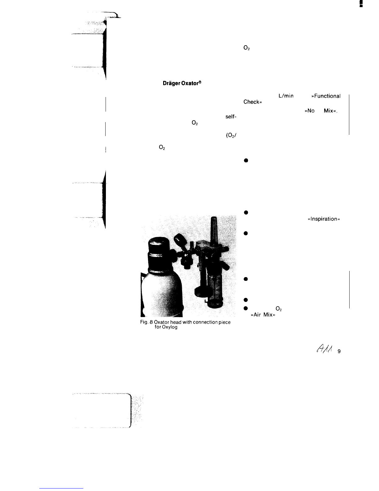
The connection piece 2M 19051 is
exclusively designed for use of the
Oxylog on the Oxator head (Fig. 8). This
connection piece is screwed to the
Oxator head and consists of a
self-
closing, standard
O2
coupling for
connection of the Oxylog using the
standard, gas-specific connector
(02/
air). A self-closing inlet screw connec-
tion for
O2
makes it possible (in addition
to the use of cylinders) to supply the
Oxylog and the other components
connected to the Oxator head (e. g.
humidifier/nebulizer or aspiration ejec-
tor) from a central gas supply unit (see
Oxator Operating Manual).
The Oxylog may not be fed via the flow
control valves at the Oxator head!
Fig.
8
Oxator
head
with
connection
piece
for
Oxylog
Use of gas blenders
.
In the case of lengthy ventilation, e. g.
during repatriation flights, low, defined
O2
concentrations may be required.
For this purpose a compressed-gas
blender can be connected upstream of
the Oxylog (see Order List).
Caution!
The inlet pressure at the Oxylog must
however be at least 2 bar at a flow rate of
approx. 60
L/min
(see
BjFunctional
Check<<
on page 11).
The switch is to be set to
a>No
Air
Mix<<.
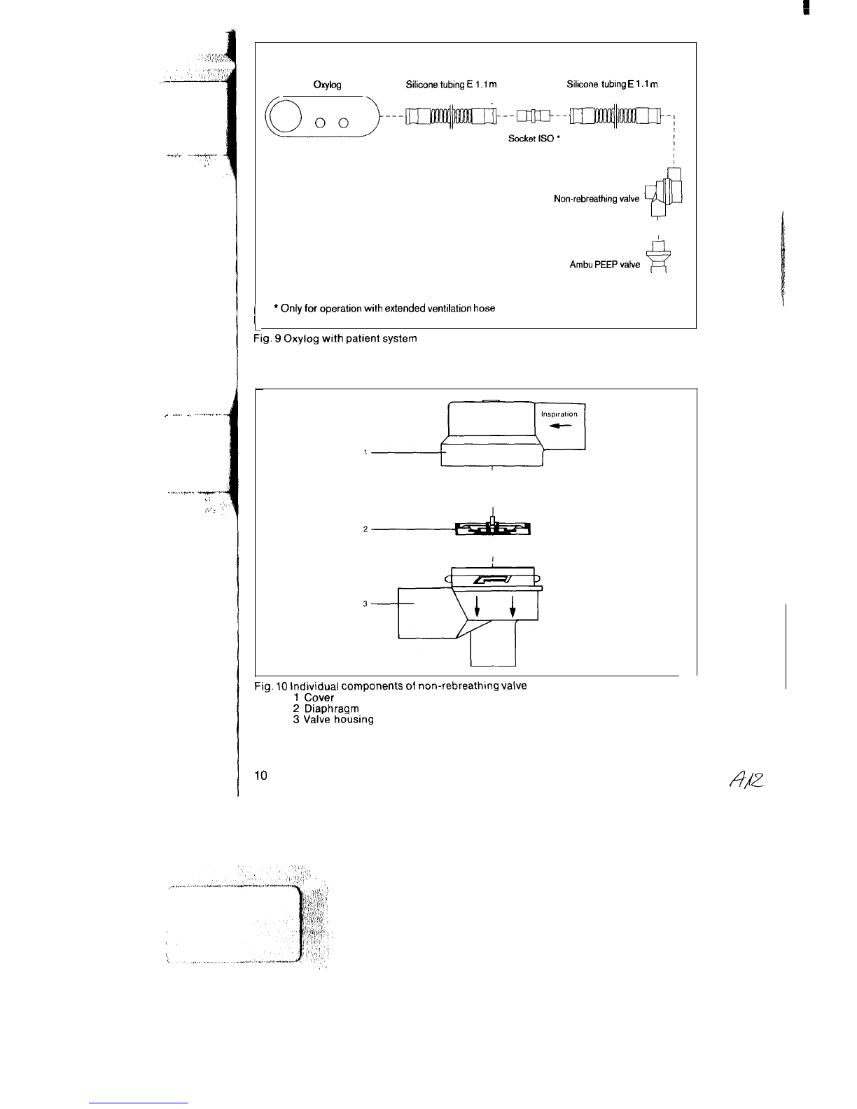
Equipping
(Fig. 9)
0
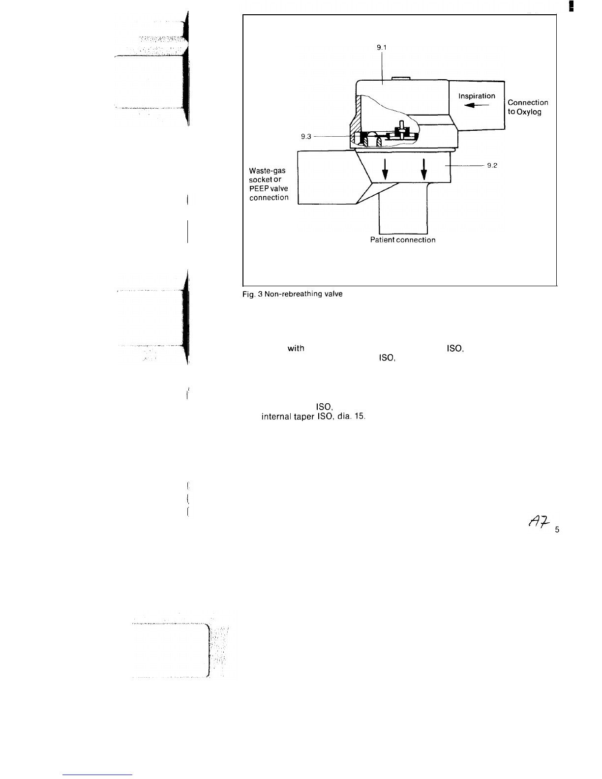
Assemble non-rebreathing valve as
per Fig. 10. Ensure that entire
diaphragm is correctly positioned
and take particular care to ensure
that red check valve is present and
not out of shape. Screw cover to
valve housing (turn 45” in clockwise
direction).
0
Attach ventilation tubing to socket at
Oxylog as well as to
~~lnspiration~~
socket on non-rebreathing valve.
0
If use is made of an (optional)
externally adjustable pressure limit-
ing valve (see Order List), attach this
valve first to the socket at the Oxylog
and then connect the ventilation
tubing to the socket of the pressure
limiting valve.
0
If PEEP is being applied, insert PEEP
valve (see Order List) into waste-gas
socket of non-rebreathing valve.
0
Set airway pressure gauge to zero.
0
Preselect
O2
concentration
a>Air
Mix<<
setting reduces drive-gas
consumption by roughly 50% as
ambient air is sucked in.