Dräger VS-2.1 User manual


Inhalt
Filter-Schutzanlage VS-2.1 3
Inhalt
1 Zu Ihrer Sicherheit . . . . . . . . . . . . . . . . . . . . . . . . . . 4
1.1 Allgemeine Sicherheitshinweise . . . . . . . . . . . . . . . 4
1.2 Beschreibung der Warnzeichen . . . . . . . . . . . . . . . 4
1.3 Produktbezogene Sicherheitshinweise . . . . . . . . . . 4
2 Beschreibung . . . . . . . . . . . . . . . . . . . . . . . . . . . . . 5
2.1 Produktübersicht . . . . . . . . . . . . . . . . . . . . . . . . . . . 5
2.2 Funktionsbeschreibung . . . . . . . . . . . . . . . . . . . . . . 6
2.2.1 Gebrauchsdauer . . . . . . . . . . . . . . . . . . . . . . . . . . . 6
2.2.2 Filterstufe G . . . . . . . . . . . . . . . . . . . . . . . . . . . . . . . 6
2.2.3 Filterstufe S . . . . . . . . . . . . . . . . . . . . . . . . . . . . . . . 6
2.2.4 Filterstufe A . . . . . . . . . . . . . . . . . . . . . . . . . . . . . . . 6
2.2.5 Ventilator . . . . . . . . . . . . . . . . . . . . . . . . . . . . . . . . . 6
2.3 Verwendungszweck . . . . . . . . . . . . . . . . . . . . . . . . 6
2.4 Einschränkungen des Verwendungszwecks . . . . . . 6
3 Montage . . . . . . . . . . . . . . . . . . . . . . . . . . . . . . . . . 6
3.1 Grundanforderungen an den Schutzraum für den
Einbau . . . . . . . . . . . . . . . . . . . . . . . . . . . . . . . . . . . 7
3.1.1 Zuluftanschluss . . . . . . . . . . . . . . . . . . . . . . . . . . . . 7
3.1.2 Abluftanschluss . . . . . . . . . . . . . . . . . . . . . . . . . . . . 7
3.1.3 Spannungsversorgung . . . . . . . . . . . . . . . . . . . . . . 7
3.1.4 Volumenstrom-Steuerung . . . . . . . . . . . . . . . . . . . . 7
3.1.5 Zusätzlich Anforderungen (Betreiberseitig) . . . . . . . 7
3.2 Verkabelung Blockstecker . . . . . . . . . . . . . . . . . . . . 8
3.3 Filter einsetzen . . . . . . . . . . . . . . . . . . . . . . . . . . . . 8
3.3.1 Vorbereitung . . . . . . . . . . . . . . . . . . . . . . . . . . . . . . 8
3.3.2 Aktivkohlefilter einsetzen . . . . . . . . . . . . . . . . . . . . . 8
3.3.3 Staub- und Schwebstofffilter einsetzen . . . . . . . . . . 9
4 Gebrauch . . . . . . . . . . . . . . . . . . . . . . . . . . . . . . . . 9
4.1 Voraussetzungen für den Gebrauch . . . . . . . . . . . . 9
4.2 Filter-Schutzanlage VS-2.1 einschalten . . . . . . . . . 9
4.3 Während des Gebrauchs . . . . . . . . . . . . . . . . . . . . 9
4.4 Nach dem Gebrauch . . . . . . . . . . . . . . . . . . . . . . . 10
5 Filterwechsel . . . . . . . . . . . . . . . . . . . . . . . . . . . . . 10
5.1 Vorbereitung für den Filterwechsel . . . . . . . . . . . . 10
5.2 Aktivkohlefilter wechseln . . . . . . . . . . . . . . . . . . . . 10
5.3 Staub- und Schwebstofffilter wechseln . . . . . . . . . 10
6 Störungsbeseitigung . . . . . . . . . . . . . . . . . . . . . . . 11
7 Wartung . . . . . . . . . . . . . . . . . . . . . . . . . . . . . . . . . 11
8 Entsorgung . . . . . . . . . . . . . . . . . . . . . . . . . . . . . . 11
8.1 Geräte- und Filterentsorgung . . . . . . . . . . . . . . . . 11
8.2 Entsorgung von Elektro- und Elektronikaltgeräten 11
9 Kennzeichnungen . . . . . . . . . . . . . . . . . . . . . . . . . 12
9.1 Typenschild . . . . . . . . . . . . . . . . . . . . . . . . . . . . . . 12
10 Technische Daten . . . . . . . . . . . . . . . . . . . . . . . . . 12
11 Bestellliste . . . . . . . . . . . . . . . . . . . . . . . . . . . . . . . 12
12 Konformitätserklärung . . . . . . . . . . . . . . . . . . . . . . 12

4 Filter-Schutzanlage VS-2.1
Zu Ihrer Sicherheit
1 Zu Ihrer Sicherheit
1.1 Allgemeine Sicherheitshinweise
Vor Gebrauch des Produkts diese Gebrauchsanweisung
und die der zugehörigen Produkte aufmerksam lesen.
Gebrauchsanweisung genau beachten. Der Anwender
muss die Anweisungen vollständig verstehen und den
Anweisungen genau Folge leisten. Das Produkt darf nur
entsprechend dem Verwendungszweck verwendet
werden.
Gebrauchsanweisung nicht entsorgen. Aufbewahrung und
ordnungsgemäße Verwendung durch die Nutzer sicher-
stellen.
Nur geschultes und fachkundiges Personal darf dieses
Produkt verwenden.
Lokale und nationale Richtlinien, die dieses Produkt
betreffen, befolgen.
Nur geschultes und fachkundiges Personal darf das
Produkt überprüfen, reparieren und instand halten. Dräger
empfiehlt, einen Service-Vertrag mit Dräger abzuschließen
und alle Instandhaltungsarbeiten durch Dräger durch-
führen zu lassen.
Für Instandhaltungsarbeiten nur Original-Dräger-Teile und
-Zubehöre verwenden. Die korrekte Funktion des Produkts
kann beeinträchtigt werden.
Fehlerhafte oder unvollständige Produkte nicht
verwenden. Keine Änderungen am Produkt vornehmen.
Dräger bei Fehlern oder Ausfallen vom Produkt oder von
Produktteilen informieren.
Diese Sprachversion der Gebrauchsanweisung entspricht
der Übersetzung der Originalgebrauchsanweisung.
1.2 Beschreibung der Warnzeichen
Die folgenden Warnzeichen werden in diesem Dokument ver-
wendet, um die zugehörigen Warntexte zu kennzeichnen und
hervorzuheben, die eine erhöhte Aufmerksamkeit seitens des
Anwenders erfordern. Die Bedeutungen der Warnzeichen sind
wie folgt definiert:
1.3 Produktbezogene Sicherheitshinweise
Manipulation unter Druck stehender Bauteile
Gefahrlose Kopplung mit elektrischen Geräten
Lagerfähigkeit von verbauten Filtern
GEFAHR
Hinweis auf eine unmittelbare Gefahrensituation.
Wenn diese nicht vermieden wird, treten Tod oder
schwere Verletzungen ein.
WARNUNG
Hinweis auf eine potenzielle Gefahrensituation. Wenn
diese nicht vermieden wird, können Tod oder schwere
Verletzungen eintreten.
VORSICHT
Hinweis auf eine potenzielle Gefahrensituation. Wenn
diese nicht vermieden wird, können Verletzungen oder
Schädigungen am Produkt oder der Umwelt eintreten.
Kann auch als Warnung vor unsachgemäßem
Gebrauch verwendet werden.
HINWEIS
Zusätzliche Information zum Einsatz des Produkts.
!
!
!
i
i
GEFAHR
Die Spannungsversorgung des Ventilators erfolgt über
einen mitgelieferten Blockstecker. Der Blockstecker
muss bei der Installation der Anlage von einem
autorisierten und ausgebildeten Elektrofachbetrieb
sachgerecht verkabelt werden.
GEFAHR
Alle Zu- undAbluftanschlüsse und Leitungen sowie die
Überwachungseinrichtungen zur Überprüfung und
Aufrechterhaltung des Überdrucks in dem Schutzraum
müssen von Betreiber bereitgestellt werden.
Ohne diese Geräte ist die Funktionsfähigkeit der
Filter-Schutzanlage VS-2.1 nicht gegeben.
GEFAHR
Der Einsatz der richtigen Filter liegt in der
Verantwortung des Anwenders. Für jeden Einsatzfall
und Schadstoff gibt es unterschiedliche Filter.
Dräger kann nur einen Hinweis geben, welche Filter
für welches Gas verwendet werden können.
VORSICHT
Klemmgefahr der Finger
Beim Wechseln der Filter muss immer vorsichtig und
umsichtig vorgegangen werden.
WARNUNG
Unter Druck stehende Bauteile, wie Schlauchenden
können sich durch Manipulation schlagartig lösen und
durch den Druckstoß lebensgefährliche Verletzungen
verursachen.
Sämtliche Arbeiten an Teilen des Gerätes dürfen
ausschließlich im ausgeschalteten Zustand
durchgeführt werden.
Schläuche und Rohrverschraubungen niemals unter
Druck lösen bzw. anziehen.
WARNUNG
Elektrische Kopplung mit Geräten, die nicht in dieser
Gebrauchsanweisung erwähnt sind, ist nur nach
Rückfrage bei den Herstellern oder einem
Sachverständigen gestattet
HINWEIS
Jedem Filter liegt ein Verpackungsetikett bei, welches
zur Identifizierung und maximalen Lagerfähigkeit des
verbauten Filters in unmittelbarer Umgebung zur
Filter-Schutzanlage VS-2.1 sichtbar aufgehängt
werden sollte.
!
!
!
!
!
!
i
i

Beschreibung
Filter-Schutzanlage VS-2.1 5
2 Beschreibung
2.1 Produktübersicht
Abb. 1 Hauptkomponenten
Abb. 2 Ausbau Aktivkohlefilter
Abb. 3 Aufnahme für Aktivkohlefilter
Abb. 4 Staubfilter-Modul
Pos. Bezeichnung
1 Staubfilter-Modul
2 Lufteinlass
3 Schnellspanner (zwei Stück)
4 Befestigungspunkte (für M8 Schrauben, 12 Stück)
5 Aktivkohlefilter-Modul
6 Spannungsversorgung
7 Luftauslass
8 Ventilator-Modul
Pos. Bezeichnung
1 Staubfilter-Modul
9 Aufnahme für Aktivkohlefilter
10 Einführungshilfen für die Aufnahme der
Aktivkohlefilter
11 Dichtung Einschub
5
6
7
8
4
3
2
1
911011
Pos. Bezeichnung
12 Dichtung (zwei Stück) (Dürfen nur verwendet werden
bei Aktivkohlefiltern ohne Lippendichtung)
13 Schnellspanner zum Fixieren der Aktivkohlefilter
(zwei pro Aktivkohlefilter)
14 Griff
15 Puffer (vier Stück)
Pos. Bezeichnung
16 Dichtung Staubfilter-Modul
17 Grobstaubfilter-Matte
18 Dichtung Filter
19 O-Ring zum Fixieren verschiedener Dichtungen
20 Lagerstifte zum Fixieren des Spannrings
21 Aufnahmezapfen Schwebstofffilter
22 Spannring für Schwebstofffilter
23 Schwebstofffilter
14
13
12
15
16 17 232220 2021 211918

6 Filter-Schutzanlage VS-2.1
Montage
2.2 Funktionsbeschreibung
Die Filter-Schutzanlage VS-2.1 bietet Schutz vor einer Vielzahl
von Stäuben, Aerosolen und Gasen. Mit voller Filterbestü-
ckung entsprechend den zu erwartenden Schadgasen bietet
die Filter-Schutzanlage VS-2.1 Schutz vor z. B.:
Grob- und Feinstäuben
Organische Gasen und Dämpfen
Anorganische Gasen und Dämpfen, wie Schwefelwasser-
stoff, Chlorgas und Zyanwasserstoff
Schwefeldioxid, Chlorwasserstoff
Ammoniak
Die Filter-Schutzanlage VS-2.1 besteht aus 3 Modulen, die zu
einer Einheit zusammengesetzt werden. Die Module sind mit
G/S (Grobstaubfilter/Schwebstofffilter), A (Aktivkohlefilter) und
V (Ventilator) bezeichnet.
Die Module V und A sind vormontiert. Das Modul G/S wird auf-
gesetzt und mithilfe zweier Schnellspanner mit dem Hauptge-
häuse verspannt. Die Schnellspanner haben eine Schnapp-
verriegelung gegen unbeabsichtigtes Lösen. Zusätzlich
können ein Vorhängeschloss sowie eine Plombierung zum
Schutz gegen unbeabsichtigtes Öffnen der Filter-Schutzan-
lage VS-2.1 verwendet werden. Die Vorspannung der Schnell-
spanner ist einstellbar.
2.2.1 Gebrauchsdauer
Allgemein gültige Richtwerte für die Gebrauchsdauer können
nicht angegeben werden, weil diese stark von den äußeren
Bedingungen abhängt, z. B. von Art und Konzentration des
Schadstoffs, Luftfeuchtigkeit und Temperatur.
Schwebstofffilter
Schwebstofffilter können sich über die Zeit dichtsetzen oder
Undichtigkeiten entwickeln.
Aktivkohlefilter
Aktivkohlefilter können nur eine gewisse Menge an Schadstof-
fen aufnehmen und verlieren über die Zeit Ihre Schutzwirkung.
2.2.2 Filterstufe G
Die Filterstufe G dient zur Abscheidung von groben Stäuben
und an Stäube gebundene Flüssigkeitstropfen (Aerosole).
2.2.3 Filterstufe S
Die Filterstufe S dient zur Abscheidung von feinsten Schweb-
stoffen und Aerosolen.
2.2.4 Filterstufe A
Die Filterstufe A dient zur Abscheidung von Gasen und Dämp-
fen, die in der Gebrauchsanweisung zum jeweiligen Filter
angegeben werden. Die Schnellspanner sind nachstellbar, die
Dichtungen einzeln austauschbar.
Die Auswahl der Filter erfolgt je nach Einsatzkonzept.
Standardmäßig werden Aktivkohlefilter der Klasse A geliefert.
Daneben stehen weitere Filtertypen zur Verfügung.
2.2.5 Ventilator
Der Ventilator saugt die Luft durch die vorgeschalteten Filter-
stufen und baut einen Überdruck im Schutzraum auf, der zum
Schutz gegen das Eindringen von Umgebungsluft dient.
2.3 Verwendungszweck
Die Filter-Schutzanlage VS-2.1 reduziert gesundheitsgefähr-
dende Stoffe in der angesaugten Luft durch drei Filterstufen
um mindestens 99 % und führt diese als gereinigte Luft dem
Schutzraum zu und bildet dabei einen Überdruck je nach
Beschaffenheit und Konzept des Schutzraums und des ver-
bauten Überdruckventils. Die Filter-Schutzanlage VS-2.1 kann
mit unterschiedlichen Filtern bedarfsgerecht bestückt werden.
Die Filter-Schutzanlage VS-2.1 kann auch im Umluftbetrieb
betrieben werden. In diesem Fall wird kein Raumüberdruck
durch die Filter-Schutzanlage VS-2.1 aufgebaut.
2.4 Einschränkungen des
Verwendungszwecks
Jede andere Verwendung außer die unter Kapitel 2.3 "Ver-
wendungszweck" erwähnte, gilt als bestimmungswidrige Ver-
wendung. Es ist insbesondere unzulässig:
Filter-Schutzanlage VS-2.1 zum Filtern von anderen
Schadstoffen als den vorgesehen zu verwenden.
Die Anlage zu verwenden, wenn die Art der Schadstoffe
und deren Konzentration nicht bekannt ist.
Die Anlage zu verwenden ohne ein Gasmessgerät für die
Messung der Gaskonzentration im Schutzraum
3 Montage
Die Anlage kann in allen Einbaulagen innerhalb und außerhalb
des Schutzraums montiert werden. Die Einbaulage senkrecht
nach unten hängend ist jedoch nicht zu empfehlen, da das Fil-
terpaket in diesem Falle gegen das Eigengewicht von unten in
die Gehäuseaufnahme eingeschoben werden muss.
Der notwendige Ausbauraum für das Filterpaket ist bei der Ein-
bauplanung zu berücksichtigen.
Hinweis
Für nähere Informationen die Bedienungsanleitungen
zu den Filtern lesen und befolgen.
i
i
GEFAHR
Lebensgefahr durch fehlerhaften Einbau!
Die Montage der Filter-Schutzanlage VS-2.1 muss
durch einen autorisierten Fachbetrieb durchgeführt
werden.
Bei fehlerhafter Montage ist die Funktionsfähigkeit der
Filter-Schutzanlage VS-2.1 nicht gegeben und es
besteht Lebensgefahr.
GEFAHR
Lebensgefahr durch Spannungsversorgung
Die Montage der Filter-Schutzanlage VS-2.1 darf
ausschließlich bei ausgeschalteter und gegen
unbeabsichtigtes Wiedereinschalten gesicherter
Spannungsversorgung durchgeführt werden.
VORSICHT
Verletzungsgefahr und Gefahr der Sachbeschädigung
durch schwierige Handhabung der Anlage
Die Anlage wiegt ca. 21 kg und lässt sich schwierig
greifen, diese Faktoren müssen bei der Montage
berücksichtigt werden.
!
!
!

Montage
Filter-Schutzanlage VS-2.1 7
Die Anlage ist mit Befestigungslaschen an allen Seiten ausge-
stattet. Die Bohrungen sind für Maschinenschrauben der
Größe M8 z. B. nach DIN 912, DIN 933 oder vergleichbar vor-
bereitet. Es müssen mindestens 4 der Befestigungslaschen
verwendet werden.
3.1 Grundanforderungen an den Schutzraum
für den Einbau
Die grundlegenden Anforderungen an den Schutzraum zur
Integration des Atemschutzsystems werden im Folgenden mit
der Filter-Schutzanlage VS-2.1 dargestellt.
3.1.1 Zuluftanschluss
Die Filter-Schutzanlage VS-2.1 saugt Umgebungsluft über
einen separaten Zuluftanschluss an. Dieser Zuluftanschluss
mit D = 80 mm muss individuell am Schutzraum eingebaut
werden.
Im Umluftbetrieb muss der Ansaugstutzen nur angeschlossen
werden, wenn die Filter-Schutzanlage VS-2.1 nicht in dem
Raum eingebaut wird, in dem die Luft gefiltert werden soll. Es
muss sichergestellt sein, dass die Luft frei aus dem Raum
angesaugt werden kann. Es ist zu beachten, dass der
Zuluftanschluss so gestaltet wird, dass der Filterwechsel nicht
behindert wird.
3.1.2 Abluftanschluss
Der Abluftanschluss hat ebenfalls einen Durchmesser von
D = 80 mm. Hier kann die Verbindung für die Abluftversorgung
fest erfolgen, da dieses Modul nicht zum Filterwechsel ausge-
baut werden muss.
3.1.3 Spannungsversorgung
Die Filter-Schutzanlage VS-2.1 wird im normalen Betrieb mit
einer Versorgungsspannung von 24 V an beiden Versor-
gungskreisen betrieben. Im „Powermodus“ wird der Versor-
gungskreis Up statt mit 24 V mit 48 V versorgt (siehe “Verka-
belung Blockstecker” auf Seite 8)
3.1.4 Volumenstrom-Steuerung
Die Volumenstrom-Steuerung erfolgt über die Vorgabe der
Steuerspannung im Bereich von 0 - 10 V DC.
3.1.5 Zusätzlich Anforderungen (Betreiberseitig)
Gasmessgerät
Zur Messung der Gaskonzentration im Schutzraum muss ein
Gasmessgerät bereitgestellt werden. Der Messwert gibt Hin-
weise auf eventuelle gefährliche Gaskonzentrationen im
Schutzraum z. B. durch gesättigte Filter und dient als Warnein-
richtung um eventuelle Gegenmaßnahmen zu ergreifen, wie
z. B. Verlassen des Gefahrenbereichs oder Anlegen der Per-
sönlichen Schutzausrüstung. Die Gegenmaßnahmen müssen
vom Betreiber beurteilt und die Mittel dafür vorgesehen wer-
den.
Überdruckventil
Zur Begrenzung des Raumüberdrucks muss ein Raum-Über-
druckventil im Schutzraum verbaut werden. Über das Über-
druckventil wird der Maximaldruck im Schutzraum begrenzt
und somit eine Beschädigung des Schutzraums vermieden.
Differenzdruck-Manometer
Zur Überwachung des Raumüberdrucks muss ein Differenz-
druck-Manometer vom Betreiber installiert werden. Das Diffe-
renzdruck-Manometer muss für den entsprechenden Druckbe-
reich ausgelegt sein. Der maximale Raumüberdruck darf
500 Pa nicht überschreiten.
Abdichtung des Schutzraums
Der Schutzraum muss so abgedichtet werden, dass sich mit
einem Atemluft-Volumenstrom von 60 m³/h ein Nutzüberdruck
von 100 bis 300 Pa einstellt. Der Nutzüberdruck stellt unter
allen Betriebsbedingungen sicher, dass keine schadstoffbelas-
tete Umgebungsluft in den Schutzraum gelangen kann. Je
nach Schutzraum sind für den nötigen Überdruck sehr unter-
schiedliche Aufwände zu treiben.
GEFAHR
Alle Zu- undAbluftanschlüsse und Leitungen sowie die
Überwachungseinrichtungen zur Überprüfung und
Aufrechterhaltung des Überdrucks in dem Schutzraum
müssen von Betreiber bereitgestellt werden.
Ohne diese Geräte ist die Funktionsfähigkeit der
Filter-Schutzanlage VS-2.1 nicht gegeben.
WARNUNG
Verletzungsgefahr und Gefahr der Sachbeschädigung
durch die Ansaugung gefährlicher Luft
Grobstaubfilter, Papierfilter und weitere Filter können
sich z. B. durch die Ansaugung von Funken in der Luft
entzünden und brennen.
Es darf ausschließlich aus Bereichen angesaugt
werden, die keine Funken bilden.
!
!
Hinweis
Nachfolgend werden zusätzliche Anforderungen an
den Schutzraum aufgeführt, die vom Betreiber
bereitgestellt werden müssen. Alle aufgeführten
Bauteile und Systeme gehören nicht zum
Lieferumfang der Filter-Schutzanlage VS-2.1 und
gewähren in ihrer Kombination nicht die vollständige
Funktion eines Schutzraums.
WARNUNG
Verletzungsgefahr und Gefahr der Sachbeschädigung
Der maximale Raumüberdruck darf 500 Pa nicht
überschreiten.
Bei höheren Gegendrücken ist eine Kühlung des
Motors nicht mehr gegeben und es kann zum Ausfall
des Motors und somit der Anlage kommen.
i
i
!

8 Filter-Schutzanlage VS-2.1
Montage
3.2 Verkabelung Blockstecker
Die Steuerspannung für die Filter-Schutzanlage VS-2.1 muss
von der Spannungsversorgung abgenommen werden. Durch
eine Brücke zwischen PIN 1 und PIN 5 kann die Filter-Schutz-
anlage VS-2.1 auf Volllast eingestellt werden.
Durch eine Brücke zwischen PIN 1 und PIN 6 erhält die Anlage
eine Dauerfreigabe und startet beim Anlegen der Spannung.
Durch eine Brücke von PIN 1 zu PIN 7 wird der „Powermodus“
48 V aktiviert. Hierfür muss zusätzlich 48 V an PIN 3 anliegen.
Ringkern
1. Kabel mit zwei Schleifen um den Ringkern so nah wie
möglich am Blockstecker von der Filter-Schutzanlage
VS-2.1 entfernt wickeln.
3.3 Filter einsetzen
3.3.1 Vorbereitung
Filter-Schutzanlage VS-2.1 ausschalten und gegen unbe-
absichtigtes Wiedereinschalten sichern.
Filter-Schutzanlage VS-2.1 in staubfreier und trockener
Umgebung öffnen.
3.3.2 Aktivkohlefilter einsetzen
1. Schnellspanner (3) öffnen um das Staubfilter-Modul (1)
abzunehmen.
2. Aufnahme der Aktivkohlefilter (9) am Griff (14) aus dem
Gehäuse herausziehen und horizontal auf eine ebene
Fläche ablegen.
3. Neue Aktivkohlefilter aus der eingeschweißten Verpa-
ckung entnehmen.
4. Bei Aktivkohlefiltern, die mit einer Lippendichtung ausge-
stattet sind, müssen die Dichtungen (12) entfernt werden.
5. Bei Aktivkohlefiltern die keine Lippendichtung haben,
müssen die Dichtungen (12) kontrolliert und ggf. ersetzt
werden. Neue Dichtungen mit O-Ringen fixieren.
6. Die neuen Aktivkohlefilter müssen mit den Pfeilen in Rich-
tung der Aufnahme (9) eingesetzt werden.
7. Anschließend müssen die beiden Schnellspanner (13) pro
Aktivkohlefilter wieder geschlossen werden.
8. Punkt 3. bis 7. für den zweiten Aktivkohlefilter wiederholen.
9. Wenn beide Aktivkohlefilter gewechselt sind, muss die Auf-
nahme mit den neuen Aktivkohlefiltern (9) wieder in das
Gehäuse der Filter-Schutzanlage VS-2.1 eingeführt wer-
den.
WARNUNG
Die Verkabelung der vom Betreiber bereitgestellten
Steuerung mit dem Stecker der Filter-Schutzanlage
VS-2.1 darf ausschließlich über einen autorisierten
und ausgebildeten Elektrofachbetrieb erfolgen.
Bei der Montage des Kabels ist darauf zu achten, dass
das betreiberseitig bereitzustellende Kabel mit zwei
Schleifen um den Ringkern so nah wie möglich am
Blockstecker der Filter-Schutzanlage VS-2.1 gewickelt
werden muss.
Hinweis
Wenn an PIN 3 24 V anliegen, darf PIN 7 nicht belegt
sein.
Pos. Bezeichnung
1 + Ue 24 V
2 - GNDe
3 Normalbetrieb: +Up 24 V
Powermodus: +Up 48 V
4 - GNDp
5 0 - 10 V (Drehzahl Steuerspannung)
6 Din (Freigabe)
7 Din (Einstellung
Anschlussspannung)
8+9+10 Nicht belegt
WARNUNG
Der Ringkern muss installiert werden, da es
andernfalls zu Fehlfunktionen und Störungen der
Filter-Schutzanlage VS-2.1 oder anderer Geräte
kommen kann.
Durch den Ringkern werden die Anforderungen der
EMV-Richtlinie eingehalten.
WARNUNG
Das Innere der Filter-Schutzanlage VS-2.1 niemals
Feuchtigkeit oder Wasser aussetzen. Filter nie im
Regen wechseln. Dadurch kann die Funktion des
Gerätes beeinträchtigt werden.
!
i
i
!
!
WARNUNG
Es müssen grundsätzlich beide Aktivkohlefilter
eingesetzt werden. Wird ein Aktivkohlefilter
weggelassen, besteht die Schutzwirkung der
Filter-Schutzanlage VS-2.1 nicht und sie arbeitet nicht
bestimmungsgemäß.
Es müssen die Standzeiten und die Herstellerangaben
zu den jeweiligen Filtern beachtet werden.
HINWEIS
Aktivkohle bindet auch an sich unbedenkliche Stoffe,
wie z. B. Wasserdampf oder Nebel.
Für den praktischen Einsatz bedeutet dies, dass
angesaugte Feuchtigkeit das Filterelement altern und
vorzeitig erschöpfen lässt. Filter daher erst kurz vor
dem Einsatz aus der Verpackung nehmen.
WARNUNG
Lebensgefahr durch fehlerhafte Filtermontage.
Werden die Filter falsch herum eingesetzt, können die
Filter in der Aufnahme verklemmen und die
Schnellspanner nicht richtig greifen. Des Weiteren ist
die Dichtheit und somit die Filterwirkung der
Filter-Schutzanlage VS-2.1 nicht mehr gegeben.
WARNUNG
Verletzungsgefahr durch fehlerhafte Montage.
Die Aufnahme für die Aktivkohlefilter muss korrekt
eingebaut werden, damit keine Undichtigkeiten
entstehen können, durch die u. U. eine gefährliche
Situation entstehen kann. Die Puffer müssen so
eingestellt sein, dass diese mindestens 1 mm über
den Gehäuserand hinausragen.
!
i
i
!
!

Gebrauch
Filter-Schutzanlage VS-2.1 9
10. Nach dem Einsetzen der Aufnahme für die
Aktivkohlefilter (9) in das Gehäuse müssen die Puffer (15)
gleichmäßig mindestens 1 mm über den Gehäuserand hin-
ausragen. Der Abstand kann durch Drehen der Puffer (15)
verändert werden.
11. Abschließend das Staubfilter-Modul aufsetzen und mithilfe
der beiden Schnellspanner (3) wieder fixieren. Die Schnell-
spanner müssen so eingestellt sein, dass diese spürbar
stramm schließen.
Die Aktivkohlefilter sind eingesetzt.
3.3.3 Staub- und Schwebstofffilter einsetzen
1. Schnellspanner (3) öffnen um das Staubfilter-Modul (1)
abzunehmen.
2. Spannring (22) im Uhrzeigersinn drehen (ca. 45°) bis die
Lagerstifte (20) in den Einspurlöchern zu sehen sind.
3. Anschließend den Spannring (22) herausnehmen.
4. Neue Grobstaubfilter-Matte (17) aus der Verpackung ent-
nehmen und einsetzen, dabei ist darauf zu achten, dass
die bedruckte Seite der Grobstaubfilter-Matte (17) zu
sehen ist und dass die Grobstaubmatte korrekt in die Auf-
nahme eingesetzt wird. Die Grobstaubfilter-Matte (17) darf
sich nicht stauchen.
5. Schwebstofffilter (23) zwischen Aufnahmezapfen (21) zen-
triert in Spannring (22) einsetzen, die Pfeilrichtung auf dem
Schwebstofffilter (23) muss zum Ventilator (8) weisen.
6. Spannring (22) mit eingesetztem Schwebstofffilter (23) so
einsetzen, dass die Lagerstifte (20) in die Einspurlöcher
passen.
7. Anschließend den Spannring (22) gegen den Uhrzeiger-
sinn drehen (ca. 45°), bis die Lagerstifte (20) in der Veran-
kerung sitzen.
8. Abschließend das Staubfilter-Modul (1) aufsetzen und mit-
hilfe der beiden Schnellspanner (3) wieder fixieren.
Der Staub- und Schwebstofffilter sind eingesetzt.
4 Gebrauch
4.1 Voraussetzungen für den Gebrauch
Die Filter-Schutzanlage VS-2.1 darf nur in einwandfreiem
Zustand betrieben werden. Der Benutzer hat vor Beginn jedes
Einsatzes die Funktion und die Einsatzfähigkeit der Anlage
durch eine Sicht- und Funktionsprüfung festzustellen.
Auf folgende Punkte ist besonders zu achten:
Verriegelungen der Schnellspanner und ggf. vorhandene
Plombierung überprüfen.
Gehäuse und äußerlich sichtbare Dichtungen auf Beschä-
digungen prüfen.
Leitungen und Schläuche auf Beschädigungen und
Anschlüsse auf dichten festen Sitz prüfen.
Kontrolle der Haltbarkeit der Filter (Verpackungsetikett
zum jeweiligen Filter)
Darüber hinaus muss der eingesetzte Filter für die zu
filternden Schadstoffen in der Umgebungsluft ausgelegt
sein.
Gasmessgerät ist laut zugehöriger Gebrauchsanweisung
eingeschaltet.
4.2 Filter-Schutzanlage VS-2.1 einschalten
Vor dem Einschalten der Anlage wird die Spannungsver-
sorgung Ue und Up angelegt. Für die Freigabe des Venti-
lators muss an PIN 6 eine Schaltspannung von 24 V
anliegen. Wenn Pin 6 gebrückt ist, läuft die Anlage mit dem
Anlegen der Spannung an.
Für den Betrieb des Schutzraums, in dem die Filter-Schutz-
anlage VS-2.1 verbaut ist, ist es wichtig, dass die Anzeige
des Differenzdruck-Manometers innerhalb kurzer Zeit auf
den vorgesehenen Wert ansteigt. Sollte die Anzeige nicht
steigen, liegt ein Fehler vor und der Schutzraum darf nicht
weiter betrieben werden, bis der Fehler behoben wird.
4.3 Während des Gebrauchs
Während des Betriebes ist regelmäßig die Schutzwirkung der
Filter-Schutzanlage VS-2.1 zu prüfen.
Grenzwerte für die Gaskonzentration mithilfe eines Gasmess-
geräts kontinuierlich kontrollieren. Bei Überschreitung der
Grenzwerte muss der Betreiber geeignete Gegenmaßnahmen
vorhalten.
Der Überdruck baut sich nur auf, wenn:
alle Öffnungen verschlossen sind,
keine Leckagen vorhanden sind,
die Filter-Schutzanlage VS-2.1 Luft fördert.
WARNUNG
Schwebstofffilter mit Pfeilrichtung zum Ventilator
einsetzen.
Wird das Schwebstofffilter nicht mit der Pfeilrichtung
zum Ventilator eingesetzt, ist die Funktionsweise nicht
gegeben.
WARNUNG
Es dürfen im gesamten Leitungssystem der Atemluft
keinerlei Leckagen vorhanden sein! Leckagen in den
Luftkanälen führen zu einem Verlust der Filterwirkung
der Filter-Schutzanlage VS-2.1.
WARNUNG
Eine Überwachung der Filterleistung durch
Schadstoffmessungen im Schutzraum wird
empfohlen. Wenn eine erhöhte
Schadstoffkonzentration festgestellt wird, sind die
Aktivkohlefilter paarweise zu ersetzen. Siehe dazu
Kapitel “Filterwechsel” auf Seite 10.
HINWEIS
Bei nicht eingelegten Filtern wird empfohlen, die
Steuerspannung von 9 V im Powermodus nicht zu
überschreiten.
!
!
!
i
i
WARNUNG
Falls das Differenzdruck-Manometer nicht einwandfrei
anzeigt, ist mindestens eine der nachfolgend
genannten Voraussetzungen nicht erfüllt.
Festgestellte Mängel sind sofort zu beheben.
Der Schutzraum ist erst nach Behebung der Mängel
wieder einsatzbereit.
!

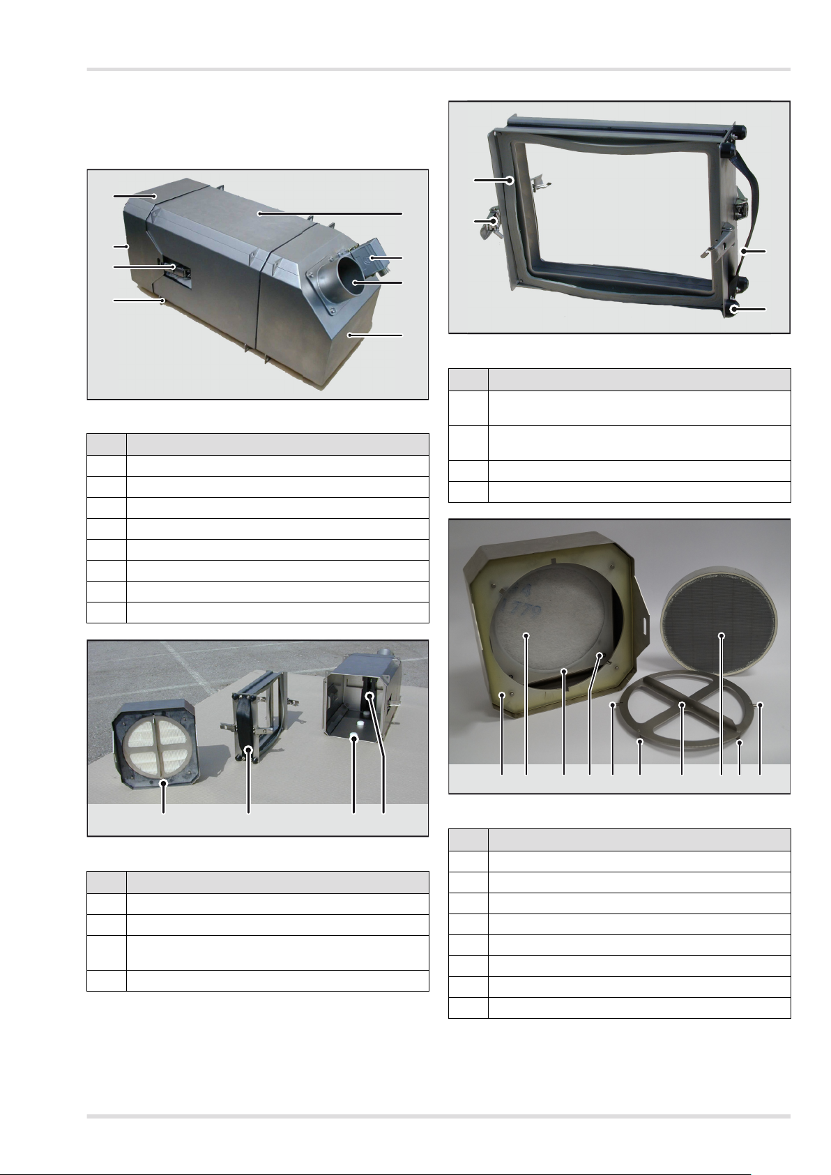
10 Filter-Schutzanlage VS-2.1
Filterwechsel
4.4 Nach dem Gebrauch
Nach Betriebsende ist die Betriebsbereitschaft der Anlage wie-
derherzustellen. Dazu sind zumindest folgende Maßnahmen
notwendig.
Sichtprüfung auf Beschädigungen
Einsatzbericht ausfüllen, sofern im Betriebskonzept vorge-
sehen. Im Einsatzbericht sind ggf. während des Einsatzes
aufgetretene Vorkommnisse zu vermerken.
Dies liegt auch im Interesse des Betreibers, weil dadurch eine
genaue Übersicht über Einsatzdauer, Bestückung und Ver-
schleiß der Filter-Schutzanlage VS-2.1 und der zugehörigen
Komponenten gewonnen wird. Außerdem ermöglicht er dem
DrägerService im Problemfall eine schnellere Fehleranalyse.
5 Filterwechsel
5.1 Vorbereitung für den Filterwechsel
Filter-Schutzanlage VS-2.1 ausschalten und gegen unbe-
absichtigtes Wiedereinschalten sichern.
Filter-Schutzanlage VS-2.1 in staubfreier und trockener
Umgebung öffnen.
5.2 Aktivkohlefilter wechseln
1. Schnellspanner (3) öffnen um das Staubfilter-Modul (1)
abzunehmen.
2. Aufnahme (9) mit den beiden Aktivkohlefiltern am Griff (14)
aus dem Gehäuse herausziehen.
3. Aufnahme der Aktivkohlefilter (9) horizontal auf eine ebene
Fläche ablegen und die beiden Schnellspanner (13) pro
Aktivkohlefilter nacheinander lösen und abklappen.
4. Aktivkohlefilter aus der Aufnahme (9) nehmen und fachge-
recht entsorgen.
5. Neue Aktivkohlefilter aus der eingeschweißten Verpa-
ckung entnehmen.
6. Bei Aktivkohlefiltern, die mit einer Lippendichtung ausge-
stattet sind, müssen die Dichtungen (12) entfernt werden.
7. Bei Aktivkohlefiltern die keine Lippendichtung haben,
müssen die Dichtungen (12) kontrolliert und ggf. ersetzt
werden. Neue Dichtungen mit O-Ringen fixieren.
8. Die neuen Aktivkohlefilter müssen mit den Pfeilen in Rich-
tung der Aufnahme (9) eingesetzt werden.
9. Anschließend müssen die beiden Schnellspanner (13) pro
Aktivkohlefilter wieder geschlossen werden.
10. Punkt 4. bis 9. für den zweiten Aktivkohlefilter wiederholen.
11. Kontrollieren der Dichtung Einschub (11) und ggf. erset-
zen. Neue Dichtung mit O-Ringen fixieren.
12. Wenn beide Aktivkohlefilter gewechselt sind, muss die Auf-
nahme mit den neuen Aktivkohlefiltern (9) wieder in das
Gehäuse der Filter-Schutzanlage VS-2.1 eingeführt wer-
den.
13. Nach dem Einsetzen der Aufnahme für die
Aktivkohlefilter (9) in das Gehäuse müssen die Puffer (15)
gleichmäßig mindestens 1 mm über den Gehäuserand hin-
ausragen. Der Abstand kann durch Drehen der Puffer (15)
verändert werden.
14.Abschließend das Staubfilter-Modul aufsetzen und mithilfe
der beiden Schnellspanner (3) wieder fixieren. Die Schnell-
spanner müssen so eingestellt sein, dass diese spürbar
stramm schließen.
Die Aktivkohlefilter sind gewechselt.
5.3 Staub- und Schwebstofffilter wechseln
1. Schnellspanner (3) öffnen um das Staubfilter-Modul (1)
abzunehmen.
2. Spannring (22) im Uhrzeigersinn drehen (ca. 45°) bis die
Lagerstifte (20) in den Einspurlöchern zu sehen sind.
3. Anschließend den Spannring (22) mit eingesetztem
Schwebstofffilter (23) herausnehmen.
4. Schwebstofffilter (23) vom Spannring (22) entfernen und
fachgerecht entsorgen.
WARNUNG
Gebrauchte Filter sind Sondermüll und müssen
entsprechend entsorgt werden.
Handschuhe und Atemschutz sind beim Wechsel der
Filter zu tragen. Sonst besteht die Gefahr erheblicher
Gesundheitsschäden. Filter fachgerecht entsorgen.
WARNUNG
Das Innere der Filter-Schutzanlage VS-2.1 niemals
Feuchtigkeit oder Wasser aussetzen. Filter nie im
Regen wechseln. Dadurch kann die Funktion des
Gerätes beeinträchtigt werden.
WARNUNG
Es müssen beide Aktivkohlefilter eingesetzt und
gewechselt werden. Wird ein Aktivkohlefilter
weggelassen, besteht die Schutzwirkung der
Filter-Schutzanlage VS-2.1 nicht und sie arbeitet nicht
bestimmungsgemäß.
Es müssen die Standzeiten und die Herstellerangaben
zu den jeweiligen Filtern beachtet werden.
Vorsicht
Bei jedem Aktivkohlefilterwechsel muss die Dichtung
Einschub (11) kontrolliert und ggf. ersetzt werden.
HINWEIS
Aktivkohle bindet auch an sich unbedenkliche Stoffe,
wie z. B. Wasserdampf oder Nebel.
Für den praktischen Einsatz bedeutet dies, dass
angesaugte Feuchtigkeit das Filterelement altern und
vorzeitig erschöpfen lässt. Filter daher erst kurz vor
dem Einsatz aus der Verpackung nehmen.
!
!
!
!
i
i
WARNUNG
Lebensgefahr durch fehlerhafte Filtermontage.
Werden die Filter falsch herum eingesetzt, können die
Filter in der Aufnahme verklemmen und die
Schnellspanner nicht richtig greifen. Des Weiteren ist
die Dichtheit und somit die Filterwirkung der
Filter-Schutzanlage VS-2.1 nicht mehr gegeben.
WARNUNG
Verletzungsgefahr durch fehlerhafte Montage.
Die Aufnahme für die Aktivkohlefilter muss korrekt
eingebaut werden, damit keine Undichtigkeiten
entstehen können, durch die u. U. eine gefährliche
Situation entstehen kann. Die Puffer müssen so
eingestellt sein, dass diese mindestens 1 mm über
den Gehäuserand hinausragen.
!
!

Störungsbeseitigung
Filter-Schutzanlage VS-2.1 11
5. Anschließend die Grobstaubfilter-Matte (17) aus der Auf-
nahme herausziehen.
6. Kontrollieren der Dichtungen (16 und 18) und ggf. erset-
zen. Die neue Dichtung Filter (18) mit O-Ringen fixieren.
7. Neue Grobstaubfilter-Matte (17) aus der Verpackung ent-
nehmen und einsetzen, dabei ist darauf zu achten, dass
die bedruckte Seite der Grobstaubfilter-Matte (17) zu
sehen ist und dass die Grobstaubmatte korrekt in die Auf-
nahme eingesetzt wird. Die Grobstaubfilter-Matte (17) darf
sich nicht stauchen.
8. Schwebstofffilter (23) zwischen Aufnahmezapfen (21) zen-
triert in Spannring (22) einsetzen, die Pfeilrichtung auf dem
Schwebstofffilter (23) muss zum Ventilator (8) weisen.
9. Spannring (22) mit eingesetztem Schwebstofffilter (23) so
einsetzen, dass die Lagerstifte (20) in die Einspurlöcher
passen.
10.Anschließend den Spannring (22) gegen den Uhrzeiger-
sinn drehen (ca. 45°), bis die Lagerstifte (20) in der Veran-
kerung sitzen.
11. Abschließend das Staubfilter-Modul (1) aufsetzen und mit-
hilfe der beiden Schnellspanner (3) wieder fixieren.
Der Staub- und Schwebstofffilter sind gewechselt.
6 Störungsbeseitigung
7 Wartung
Vor jedem Einsatz der Filter-Schutzanlage VS-2.1
Anlage auf Beschädigungen und Leckagen prüfen
Befestigung der Komponenten und Schläuche prüfen
Jährlich oder alle 2000 Betriebsstunden
Wartung der Anlage durch speziell ausgebildetes Fachper-
sonal
Alle 4 Jahre
Wartung der Anlage inklusive Austausch aller Dichtungen
durch speziell ausgebildetes Fachpersonal
8 Entsorgung
8.1 Geräte- und Filterentsorgung
Bei der Entsorgung von Geräten und Filtern fallen Abfälle
unterschiedlicher Abfallarten an. Es muss zwischen gefährli-
chen und ungefährlichen Abfällen unterschieden werden, die
gemäß den lokal geltenden Richtlinien und Vorschriften ent-
sorgt werden müssen.
8.2 Entsorgung von Elektro- und
Elektronikaltgeräten
Elektro- und Elektronikaltgeräte unterliegen nationalen
und internationalen Entsorgungsvorschriften und
dürfen nicht als Siedlungsabfall entsorgt werden. Sie
sind daher mit dem nebenstehenden Symbol gekenn-
zeichnet. Weitere Informationen können im Internet
unter www.draeger.com abgerufen werden.
Dräger nimmt Elektro- und Elektronikaltgeräte zurück und führt
diese dem Recycling oder der Entsorgung zu.
Vorsicht
Bei jedem Staub- und Schwebstofffilterwechsel
müssen die Dichtungen (16 und 18) kontrolliert und
ggf. ersetzt werden.
Hinweis
Der Grobstaubfilter ist als rahmenlose Vliesmatte
ausgeführt und kann nach dem Herausnehmen durch
Ausklopfen, Aussprühen oder Auswaschen und
Trocknen gereinigt und anschließend ggf. mehrfach
wiederverwendet werden.
WARNUNG
Schwebstofffilter mit Pfeilrichtung zum Ventilator
einsetzen.
Wird das Schwebstofffilter nicht mit der Pfeilrichtung
zum Ventilator eingesetzt, ist die Funktionsweise nicht
gegeben.
Fehler Ursache Abhilfe
Gebläse läuft
nicht
keine Spannung am
Gerät
Spannungsversor-
gung prüfen
Ansteuerungselek-
tronik defekt
DrägerService
kontaktieren
Gebläse lässt
sich nicht
regeln
Ansteuerungselek-
tronik defekt
DrägerService
kontaktieren
!
i
i
!
Luftstrom am
Austrittstutzen
zu gering
Deckel nicht
geschlossen und
verriegelt
Deckel schließen
und verriegeln
Dichtung Einschub
oder Staubfilter-
Modul beschädigt
oder falsch
eingesetzt
Dichtung Einschub
oder Staubfilter-
Modul ersetzen
oder korrekt
einsetzen
Aktivkohle-,
Grobstaub- oder
Schwebstofffilter
dicht
Aktivkohle-,
Grobstaub- oder
Schwebstofffilter
wechseln
Ansteuerungselek-
tronik defekt
DrägerService
kontaktieren
WARNUNG
Lebensgefahr beim Wechsel gebrauchter Filter
Gebrauchte Filter sind Sondermüll und müssen
entsprechend fachgerecht entsorgt werden.
Handschuhe und Atemschutz sind beim Wechsel der
Filter zu tragen.
Fehler Ursache Abhilfe
!

12 Filter-Schutzanlage VS-2.1
Kennzeichnungen
9 Kennzeichnungen
9.1 Typenschild
Das Typenschild befindet sich rechts neben dem Anschluss
der Spannungsversorgung.
Abb. 5 Typenschild (exemplarisch)
10 Technische Daten
11 Bestellliste
12 Konformitätserklärung
WARNUNG
Die Sicherheitskennzeichnungen an der Anlage nicht
entfernen oder verändern. Beschädigte oder
verlorengegangene Sicherheitskennzeichnungen
sofort originalgetreu ersetzen.
Bezeichnung Maßzahl
Elektrischer Anschluss
Nennspannung 24 V/48 V DC
Stromaufnahme
- 24 V (Normalbetrieb)
- 48 V (Powermodus)
max. 3 A
max. 7 A
Maße und Gewichte
Hauptmaße (geschlossen) ca. 595 x 250 x 270 mm
(L x B x H)
Lufteinlass Ø 80 mm (Länge 50 mm)
Luftauslass Ø 80 mm (Länge 50 mm)
Gewicht 21 kg (betriebsbereit, mit
voller Filterbestückung)
Lieferleistung
Luftvolumenstrom, nominal
- 24 V (Normalbetrieb)
- 48 V (Powermodus)
65 m³/h bei 300Pa
Nutzüberdruck
105 m³/h bei 300Pa
Nutzüberdruck
Umgebungsbedingungen
Temperaturbereich/ Betrieb -30 °C bis +60 °C
Filter
Staubfilter
Schwebstofffilter
Aktivkohlefilter Typen
Volumenstrom
Volumenstrom in m³/h bei un-
beladenen Filtern
Nutzüberdruck
0 Pa 300 Pa 500 Pa
Normalbetrieb 90 65 50
Powermodus 125 105 90
!
Benennung Sachnr.
Filter-Schutzanlage VS-2.1, bestehend aus
Filtergehäuse mit Gebläseeinheit, ohne
Filtersatz
69 23 060
Filterauswahl
Großstaubfilter 65 26 804
Schwebstofffilter, Partikelfilter H13 65 26 805
Aktivkohlefilter A2 (enthält 2 Filter) 67 37 070
Aktivkohlefilter A2B2E2K1Hg (enthält 2 Filter) 67 37 071
Dichtungen
Dichtung Einschub 65 51 916
Dichtung Filter 65 34 319
Dichtung Staubfilter-Modul 65 51 914
Dichtung Aktivkohlefilter
(enthält 2 Dichtungen)
65 26 559
O-Ringe zum Fixieren der Dichtungen
(enthält 10 O-Ringe)
T 53 238
Zubehör
Differenzdruck-Manometer 65 55 849
12 V auf 24 V Konverter 65 32 638

Content
Filter Protection System VS-2.1 13
Content
1 For your safety . . . . . . . . . . . . . . . . . . . . . . . . . . . 14
1.1 General safety statements . . . . . . . . . . . . . . . . . . 14
1.2 Definitions of alert icons . . . . . . . . . . . . . . . . . . . . 14
1.3 Product-related safety statements . . . . . . . . . . . . 14
2 Description . . . . . . . . . . . . . . . . . . . . . . . . . . . . . . 15
2.1 Product overview . . . . . . . . . . . . . . . . . . . . . . . . . . 15
2.2 Description of functions . . . . . . . . . . . . . . . . . . . . . 16
2.2.1 Service life . . . . . . . . . . . . . . . . . . . . . . . . . . . . . . . 16
2.2.2 Filter stage C . . . . . . . . . . . . . . . . . . . . . . . . . . . . . 16
2.2.3 Filter stage S . . . . . . . . . . . . . . . . . . . . . . . . . . . . . 16
2.2.4 Filter stage A . . . . . . . . . . . . . . . . . . . . . . . . . . . . . 16
2.2.5 Fan . . . . . . . . . . . . . . . . . . . . . . . . . . . . . . . . . . . . 16
2.3 Intended use . . . . . . . . . . . . . . . . . . . . . . . . . . . . . 16
2.4 Limitations on use . . . . . . . . . . . . . . . . . . . . . . . . . 16
3 Installation . . . . . . . . . . . . . . . . . . . . . . . . . . . . . . . 16
3.1 Basic installation requirements concerning the shelter
. . . . . . . . . . . . . . . . . . . . . . . . . . . . . . . . . . . . . . . . 17
3.1.1 Air inlet connection . . . . . . . . . . . . . . . . . . . . . . . . 17
3.1.2 Air exhaust connection . . . . . . . . . . . . . . . . . . . . . 17
3.1.3 Power supply . . . . . . . . . . . . . . . . . . . . . . . . . . . . . 17
3.1.4 Volume flow rate control . . . . . . . . . . . . . . . . . . . . 17
3.1.5 Additional requirements (on the operator side) . . . 17
3.2 Block connector cabling . . . . . . . . . . . . . . . . . . . . 17
3.3 Inserting the filters . . . . . . . . . . . . . . . . . . . . . . . . . 18
3.3.1 Preparation . . . . . . . . . . . . . . . . . . . . . . . . . . . . . . 18
3.3.2 Inserting the activated carbon filter . . . . . . . . . . . . 18
3.3.3 Inserting the dust and suspended matter filters . . 19
4 Use . . . . . . . . . . . . . . . . . . . . . . . . . . . . . . . . . . . . 19
4.1 Prerequisites for use . . . . . . . . . . . . . . . . . . . . . . . 19
4.2 Switching on the Filter Protection System VS-2.1 . 19
4.3 During use . . . . . . . . . . . . . . . . . . . . . . . . . . . . . . . 19
4.4 After use . . . . . . . . . . . . . . . . . . . . . . . . . . . . . . . . 20
5 Filter replacement . . . . . . . . . . . . . . . . . . . . . . . . . 20
5.1 Preparations for filter replacement . . . . . . . . . . . . 20
5.2 Replacing the activated carbon filter . . . . . . . . . . . 20
5.3 Replacing the dust and suspended matter filters . 21
6 Troubleshooting . . . . . . . . . . . . . . . . . . . . . . . . . . 21
7 Maintenance . . . . . . . . . . . . . . . . . . . . . . . . . . . . . 21
8 Disposal . . . . . . . . . . . . . . . . . . . . . . . . . . . . . . . . 21
8.1 Disposal of devices and filters . . . . . . . . . . . . . . . . 21
8.2 Disposal of waste electrical and electronic equipment
. . . . . . . . . . . . . . . . . . . . . . . . . . . . . . . . . . . . . . . . 21
9 Markings . . . . . . . . . . . . . . . . . . . . . . . . . . . . . . . . 22
9.1 Rating plate . . . . . . . . . . . . . . . . . . . . . . . . . . . . . . 22
10 Technical data . . . . . . . . . . . . . . . . . . . . . . . . . . . . 22
11 Order list . . . . . . . . . . . . . . . . . . . . . . . . . . . . . . . . 22
12 Declaration of Conformity . . . . . . . . . . . . . . . . . . . 22

14 Filter Protection System VS-2.1
For your safety
1 For your safety
1.1 General safety statements
Before using the product, carefully read the instructions for
use and those for the associated products.
Strictly follow the instructions for use. The user must
understand the instructions completely and follow them
precisely. The product is only permitted to be used in
accordance with its intended use.
Do not throw away instructions for use. Ensure storage and
proper use by the user.
Only trained, expert personnel may use this product.
Follow local and national guidelines that affect this product.
Only trained, expert personnel are permitted to check,
repair, and service the product. Dräger recommends a
Dräger service contract for all maintenance activities and
that all repairs are carried out by Dräger.
Use only genuine Dräger spare parts and accessories. The
correct function of the product may be impaired.
Do not use a faulty or incomplete product. Do not modify
the product.
Notify Dräger in the event of faults or failures in the product
or in product parts.
This language version of the instructions for use is a
translation of the original instructions for use.
1.2 Definitions of alert icons
The following alert icons are used in this document to identify
and highlight the associated alert texts that require an
increased level of care on the part of the user. The meanings
of the alert icons are defined as follows:
1.3 Product-related safety statements
Manipulation of pressurized components
Hazard-free attachment to electrical device
Storage life of installed filters
DANGER
Indicates a situation of immediate danger. If this
situation is not avoided, death or severe injury will
occur.
WARNING
Indicates a situation of potential danger. If this situation
is not avoided, death or severe injury may occur.
CAUTION
Indicates a situation of potential danger. If this situation
is not avoided, injuries or damage to the product or
environment may occur. May also be used as a
warning against improper use.
NOTICE
Additional information regarding the use of the
product.
!
!
!
i
i
DANGER
The fan is supplied with power via a supplied block
connector. During the installation of the system, the
block connector must be properly cabled by a certified
and trained electrician.
DANGER
All air inlet and exhaust connections and lines, as well
as the monitoring equipment for verifying and
maintaining the overpressure in the shelter, must be
provided by the operator.
Without these devices the operation of the
Filter Protection System VS-2.1 is not guaranteed.
DANGER
The user is responsible for ensuring that the correct
filters are used. There are different filters for each
specific application area and contaminant.
Dräger is only able to provide a recommendation as to
which filters can be used for which gas.
CAUTION
Risk of crushing fingers
When changing the filter, always proceed with caution
and care.
WARNING
Pressurized parts, such as hose ends, may become
suddenly loose due to manipulation and cause life-
threatening injuries due to the surge in pressure.
All work on any parts of the device must only be carried
out when the device is switched off.
Never unfasten or tighten hoses and pipe connections
under pressure.
WARNING
Electrical connection to devices not mentioned in
these instructions for use is only permitted following
consultation with the manufacturers or an expert.
NOTICE
Each filter includes a packaging label which should be
visibly displayed in the immediate vicinity of the
Filter Protection System VS-2.1 for identification and
information on the maximum storage life of the
installed filter.
!
!
!
!
!
!
i
i

Description
Filter Protection System VS-2.1 15
2 Description
2.1 Product overview
Fig. 1 Main components
Fig. 2 Removal of the activated carbon filter
Fig. 3 Receptacle for activated carbon filter
Fig. 4 Dust filter module
Pos. Designation
1 Dust filter module
2 Air inlet
3 Quick release (two pieces)
4 Fastening points (for M8 screws, 12 pieces)
5 Activated carbon filter module
6 Power supply
7 Air outlet
8 Fan module
Pos. Designation
1 Dust filter module
9 Receptacle for activated carbon filter
10 Insertion aids for receiving the activated carbon filters
11 Seal for insert
5
6
7
8
4
3
2
1
911011
Pos. Designation
12 Seal (x2) (may only be used on activated carbon
filters without lip seal)
13 Quick release for fixing the activated carbon filter in
place
(two for each activated carbon filter)
14 Handle
15 Pad (x4)
Pos. Designation
16 Seal for dust filter module
17 Coarse dust filter mat
18 Seal for filter
19 O-ring for fixing various seals in place
20 Bearing pins for fixing the clamping ring
21 Receptacle pin for suspended matter filter
22 Clamping ring for suspended matter filter
23 Suspended matter filter
14
13
12
15
16 17 232220 2021 211918

16 Filter Protection System VS-2.1
Installation
2.2 Description of functions
The Filter Protection System VS-2.1 provides protection
against a wide variety of dusts, aerosols and gases. When
fitted with all the filters corresponding to the harmful gases
expected, the Filter Protection System VS-2.1 provides
protection against, for example:
Coarse and fine dusts
Organic gases and vapors
Inorganic gases and vapors, such as hydrogen sulfide,
chlorine gas and hydrogen cyanide
Sulfur dioxide, hydrogen chloride
Ammonia
The Filter Protection System VS-2.1 consists of 3 modules
which can be combined to form a single unit. These modules
are designated as C/S (coarse dust filter/suspended matter
filter), A (activated carbon filter), and F (fan).
The F and A modules are preinstalled. The C/S module is
attached and clamped to the main housing with the aid of two
quick releases. The quick releases have a snap-lock system to
prevent unintentional release. In addition, a padlock and a
sealing ring can be used to prevent the unintended opening of
the Filter Protection System VS-2.1. The pretension of the
quick releases can be adjusted.
2.2.1 Service life
It is not possible to give general guideline values concerning
the service life because this is strongly dependent on the
external conditions, e.g. on the type and concentration of the
contaminant, humidity and temperature.
Suspended matter filter
Suspended matter filters may become clogged or develop
leaks over time.
Activated carbon filter
Activated carbon filters are only able to absorb a certain
amount of contaminants, and lose their protective effect over
time.
2.2.2 Filter stage C
Filter stage C is used to separate coarse dusts and liquid
droplets (aerosols) attached to dusts.
2.2.3 Filter stage S
Filter stage S is used to separate very fine suspended matter
and aerosols.
2.2.4 Filter stage A
Filter stage A is used to separate gases and vapors as
specified in the instructions for use for the respective filter. The
quick releases are adjustable. The seals can be replaced
individually.
The choice of filters used depends on the application concept.
Class A activated charcoal filters are supplied as standard.
Other types of filters are also available.
2.2.5 Fan
The fan draws the air through the upstream filter stages and
generates an overpressure in the shelter which serves for
protection against the ingress of ambient air.
2.3 Intended use
The Filter Protection System VS-2.1 uses three filter stages to
reduce harmful substances in the intake air by at least 99%,
and supplies this air to the shelter as purified air, in the process
generating an overpressure depending on the characteristics
and design of the shelter and of the installed relief valve. The
Filter Protection System VS-2.1 can be equipped with a range
of filters as needed. The Filter Protection System VS-2.1 can
also be operated in recirculation mode. In this case, the
Filter Protection System VS-2.1 does not generate an
overpressure.
2.4 Limitations on use
Any use other than that described in chapter 2.3 "Intended
use" should be regarded as incorrect use. Especially the
following points are not permitted:
Use of the Filter Protection System VS-2.1 to filter
contaminants other than those intended.
Use of the system when the type and concentration of
contaminants is not known.
Use of the system without a gas detector to measure the
gas concentration in the shelter
3 Installation
The system can be installed in any installation position inside
and outside the shelter. The installation position hanging
vertically downwards is however not recommended because in
this case the filter package has to be inserted against its own
weight from below into the housing receptacle.
The necessary expansion space for the filter package must be
considered when planning the installation.
The system is equipped with fastening lugs on all sides. The
holes are prepared for machine screws of size M8 according
to DIN 912 and DIN 933, for example, or comparable. A
minimum of 4 fastening lugs must be used.
Note
For more information, read and follow the operating
instructions for the filters.
i
i
DANGER
Danger to life due to incorrect installation!
The Filter Protection System VS-2.1 must be installed
by a certified electrician.
If installation is not carried out correctly, the operation
of the Filter Protection System VS-2.1 is not ensured
and there is a danger to life.
DANGER
Risk to life due to power supply
Installation of the Filter Protection System VS-2.1 may
only be performed when the power supply has been
disconnected and secured against inadvertent
reconnection.
CAUTION
Risk of injury and property damage due to the difficult
handling of the system
The system weighs approx. 21 kg and is hard to grip.
These factors must be taken into account for
installation.
!
!
!

Installation
Filter Protection System VS-2.1 17
3.1 Basic installation requirements
concerning the shelter
The basic requirements for the shelter for the integration of the
respiratory protection system are described below with
reference to the Filter Protection System VS-2.1.
3.1.1 Air inlet connection
The Filter Protection System VS-2.1 draws in ambient air
through a separate air inlet connection. This air inlet
connection with D = 80 mm must be installed individually on
the shelter.
In recirculation mode, it is only necessary to connect the intake
connection if the Filter Protection System VS-2.1 is not
installed in the room in which the air should be filtered. It must
be ensured that the air can be freely drawn in from the room.
Care must be taken to design the air inlet connection so that
the replacement of filters is not hindered.
3.1.2 Air exhaust connection
The air exhaust connection also has a diameter of D = 80 mm.
The exhaust air outlet can have a fixed connection here
because this module does not need to be removed for filter
replacement.
3.1.3 Power supply
The Filter Protection System VS-2.1 is powered by a supply
voltage of 24 V on both supply circuits. In "Power mode", the
'Up' supply circuit is supplied with 48 V instead of 24 V (see
"Block connector cabling" on page 17)
3.1.4 Volume flow rate control
The volume flow rate is controlled by setting the control voltage
in the range of 0 - 10 V DC.
3.1.5 Additional requirements (on the operator side)
Gas detector
A gas detector must be provided for measuring the gas
concentration in the shelter. The measured value serves to
indicate possible dangerous gas concentrations in the shelter,
for example due to saturated filters, and is intended as a
warning device for the initiation of any countermeasures, such
as leaving the danger zone or donning personal protective
equipment. These countermeasures must be assessed by the
operator and the means for these must be provided.
Relief valve
A room relief valve must be installed in the shelter to limit the
room overpressure. The relief valve is used to limit the
maximum pressure in the shelter, thereby preventing damage
to the shelter.
Differential pressure gauge
A differential pressure gauge must be installed by the operator
in order to monitor the room overpressure. The differential
pressure gauge must be configured for the relevant pressure
range. The maximum room overpressure must not exceed
500 Pa.
Sealing the shelter
The shelter must be sealed in such a way that an effective
overpressure of 100 to 300 Pa is produced at a breathing air
volume flow rate of 60 m³/h. The effective overpressure
ensures under all operating conditions that no contaminated
ambient air can enter into the shelter. The effort required to
create the necessary overpressure differs greatly depending
on the shelter.
3.2 Block connector cabling
The control voltage for the Filter Protection System VS-2.1
must be taken from the power supply. By using a jumper
between PIN 1 and PIN 5 the Filter Protection System VS-2.1
can be set to full load.
DANGER
All air inlet and exhaust connections and lines, as well
as the monitoring equipment for verifying and
maintaining the overpressure in the shelter, must be
provided by the operator.
Without these devices the operation of the
Filter Protection System VS-2.1 is not guaranteed.
WARNING
Risk of injury and property damage due to the intake of
dangerous air
Coarse dust filters, paper filters, and other filters can
ignite, for example due to the intake of sparks in the air.
Only draw in air from areas where sparks do not occur.
Note
Below is a list of additional requirements for the shelter
which must be provided by the operator. All of the
components and systems listed do not form part of the
scope of delivery of the Filter Protection System
VS-2.1, and the combination of these does not provide
the full function of a shelter.
!
!
i
i
WARNING
Risk of injury and of damage to equipment.
The maximum room overpressure must not exceed
500 Pa.
At higher counterpressures, cooling of the motor is no
longer ensured, which can lead to the failure of the
motor and the system.
WARNING
The cabling of the control provided by the operator with
the plug of the Filter Protection System VS-2.1 must
only be carried out by a certified and trained
electrician.
When installing the cable, note that the cable to be
provided by the operator must be wound with two
loops around the ring core as close as possible to the
block connector of the Filter Protection System
VS-2.1.
!
!

18 Filter Protection System VS-2.1
Installation
A bridge between PIN 1 and PIN 6 means that the system is
continuously released and will start as soon as power is
applied.
The 48 V "power mode" is activated via a bridge between PIN
1 and PIN 7. Additionally, 48 V must be applied to PIN 3 for this
purpose.
Ring core
Wind the cable with two loops around the ring core as close as
possible to the block connector of the Filter Protection System
VS-2.1.
3.3 Inserting the filters
3.3.1 Preparation
Switch off the Filter Protection System VS-2.1 and secure
to prevent unintentional reactivation.
Open the Filter Protection System VS-2.1 in a dry and
dust-free environment.
3.3.2 Inserting the activated carbon filter
1. Undo the quick releases (3) to remove the dust filter
module (1).
2. Take the activated carbon filter receptacle (9) by the
handle (14) and remove from the housing; place it
horizontally on a level surface.
3. Remove new activated carbon filters from the shrink-
wrapped packaging.
4. For activated carbon filters provided with a lip seal, the
seals (12) must be removed.
5. For activated carbon filters with no lip seal, the seals (12)
must be checked and replaced if necessary. Fix new seals
in place using O-rings.
6. The new activated carbon filters must be inserted with the
arrows facing in the direction of the receptacle (9).
7. The two quick releases (13) for each activated carbon filter
must then be closed again.
8. Repeat points 3. to 7. for the second activated carbon filter.
9. Once both activated carbon filters have been replaced, the
receptacle (9) with the new activated carbon filters must be
inserted again into the housing of the
Filter Protection System VS-2.1.
10.After inserting the receptacle (9) for the activated carbon
filters into the housing, the pads (15) must project uniformly
by at least 1 mm beyond the edge of the housing. The
spacing can be varied by rotating the pads (15).
Note
If 24 V is applied to PIN 3, PIN 7 must not be assigned.
Item Designation
1 + Ue 24 V
2 - GNDe
3 Normal operation: +Up 24 V
Power mode: +Up 48 V
4 - GNDp
5 0 - 10 V (rotational speed of control
voltage)
6 DIN (release)
7 DIN (supply voltage setting)
8+9+10 Not assigned
WARNING
The ring core must be installed otherwise malfunctions
and faults may occur in the Filter Protection System
VS-2.1 or other devices.
The ring core ensures compliance with the
requirements of the EMC directive.
WARNING
Never expose the inside of the
Filter Protection System VS-2.1 to moisture or water.
Never replace filters in the rain. This can impair the
function of the device.
i
i
!
!
WARNING
Both activated carbon filters must always be inserted.
If one of the activated carbon filters is not inserted, the
protective effect of the Filter Protection System VS-2.1
will not be available and it cannot be used in a manner
conforming to its intended use.
Observe the respective service life and the
manufacturer specifications relating to each filter.
NOTICE
Activated carbon also binds harmless substances,
such as water vapor or mist.
For practical use, this means that humidity intake ages
the filter element and may shorten its service life. For
this reason, only remove the filter from the packaging
shortly before using.
WARNING
Danger to life due to incorrect filter installation.
If the filters are inserted the wrong way round, the
filters may jam in the receptacle and the quick releases
will not engage properly. Furthermore, the tightness
and thus the filtering action of the
Filter Protection System VS-2.1 is no longer ensured.
WARNING
Risk of injury if incorrectly assembled.
The receptacle for the activated carbon filters must be
correctly installed to ensure that no leakages can
occur, which could lead to a hazardous situation in
some circumstances. The pads must be positioned
such that they project at least 1 mm beyond the edge
of the housing.
!
i
i
!
!

Use
Filter Protection System VS-2.1 19
11. Finally, fit the dust filter module and fix it again with the help
of the two quick releases (3). The quick releases must be
positioned in such a way that they are obviously tightly
closed.
The activated carbon filters are now inserted.
3.3.3 Inserting the dust and suspended matter filters
1. Undo the quick releases (3) to remove the dust filter
module (1).
2. Turn the clamping ring (22) in a clockwise direction
(approx. 45°) until the bearing pins (20) can be seen in the
single-track holes.
3. Then remove the clamping ring (22).
4. Remove the new coarse dust filter mat (17) from the
packaging and insert it. While doing so, make sure that the
printed side of the coarse dust filter mat (17) can be seen
and that the coarse dust mat is inserted correctly into the
receptacle. The coarse dust filter mat (17) must not be
compressed.
5. Insert the suspended matter filter (23) between the
receptacle pin (21) centered in the clamping ring (22); the
direction of the arrow on the suspended matter filter (23)
must face towards the fan (8).
6. Insert the clamping ring (22) with the inserted suspended
matter filter (23) so that the bearing pins (20) fit into the
single-track holes.
7. Then turn the clamping ring (22) in a counterclockwise
direction (approx. 45°), until the bearing pins (20) are
seated in their fixtures.
8. Finally, fit the dust filter module (1) and fix it in place again
with the help of the two quick releases (3).
The dust and suspended matter filters are now inserted.
4 Use
4.1 Prerequisites for use
The Filter Protection System VS-2.1 may only be operated in
technically perfect condition. The user should perform a visual
and functional check before every use to establish the function
and usability of the system.
Special attention must be paid to the following points:
Check the locks on the quick releases and the sealing ring
(if present).
Check the housing and the externally visible seals for
damage.
Check lines and hoses for damage and connectors for a
tight, firm seat.
Check the storage life of the filters (packaging label for the
respective filter).
In addition, the filter used must be designed for the
contaminants to be filtered out of the ambient air.
The gas detector has been switched on in accordance with
the corresponding instruction for use.
4.2 Switching on the
Filter Protection System VS-2.1
Before switching on the system, the Ue and Up power
supply is applied. To release the fan, a switching voltage of
24 V must be applied to PIN 6. If PIN 6 is bridged, the
system will start when voltage is applied.
To operate the shelter in which the
Filter Protection System VS-2.1 is installed, it is important
that the reading on the differential pressure gauge rises to
the intended value within a short period of time. If the value
in the display does not increase, there is an error and the
shelter must not be operated further until the error has
been rectified.
4.3 During use
During operation, the protective effect of the
Filter Protection System VS-2.1 must be checked on a regular
basis.
Continuously check the limit values for the gas concentration
with the aid of a gas detector. If the limit values are exceeded,
appropriate countermeasures must be initiated by the
operator.
The overpressure is only built up if:
all openings are closed
no leaks are present
the Filter Protection System VS-2.1 conveys air.
WARNING
Insert the suspended matter filter with the direction of
the arrow towards the fan.
If the suspended matter filter is not inserted with the
direction of the arrow pointing towards the fan, its
proper functioning will not be ensured.
WARNING
There must not be any leaks in any part of the
breathing air piping system! Leaks in the air ducts will
lead to a loss of the filtering action of the
Filter Protection System VS-2.1.
WARNING
It is recommended that the performance of the filters is
monitored by measuring contaminants in the shelter. If
an increased contaminant concentration is detected,
the activated carbon filters must be replaced in pairs.
For more information, refer to chapter "Filter
replacement" on page 20.
NOTICE
If filters have not been inserted, not exceeding the
control voltage of 9 V in power mode is recommended.
!
!
!
i
i
WARNING
If the display of the differential pressure manometer
does not function properly, at least one of the following
prerequisites has not been met.
Any faults found must be rectified immediately.
The shelter is only ready for operation again after the
faults have been rectified.
!

20 Filter Protection System VS-2.1
Filter replacement
4.4 After use
After the end of operation, place the system back into a state
of operational readiness. This requires at least the following
measures.
Carry out a visual inspection for damage
Complete the mission report, if provided in the operating
concept. Any incidents that occurred during the mission
must be included in the mission report.
This is also in the interest of the operator because it provides
a detailed overview of the duration of use, the equipment fitted
and the degree of wear of the Filter Protection System VS-2.1
and the corresponding components. It also allows
DrägerService to quickly identify faults in case of problems.
5 Filter replacement
5.1 Preparations for filter replacement
Switch off the Filter Protection System VS-2.1 and secure
to prevent unintentional reactivation.
Open the Filter Protection System VS-2.1 in a dry and
dust-free environment.
5.2 Replacing the activated carbon filter
1. Undo the quick releases (3) to remove the dust filter
module (1).
2. Take the receptacle (9) with the two activated carbon filters
by the handle (14) and remove from the housing.
3. Place the activated carbon filter receptacle (9) horizontally
on a level surface and release and fold down the two quick
releases (13) for each activated carbon filter in succession.
4. Remove the activated carbon filters from the receptacle (9)
and dispose of correctly.
5. Remove new activated carbon filters from the shrink-
wrapped packaging.
6. For activated carbon filters provided with a lip seal, the
seals (12) must be removed.
7. For activated carbon filters with no lip seal, the seals (12)
must be checked and replaced if necessary. Fix new seals
in place using O-rings.
8. The new activated carbon filters must be inserted with the
arrows facing in the direction of the receptacle (9).
9. The two quick releases (13) for each activated carbon filter
must then be closed again.
10. Repeat points 4. to 9. for the second activated carbon filter.
11. Check the seal on the insert (11) and replace if necessary.
Fix new seal in place using O-rings.
12. Once both activated carbon filters have been replaced, the
receptacle (9) with the new activated carbon filters must be
inserted again into the housing of the
Filter Protection System VS-2.1.
13.After inserting the receptacle (9) for the activated carbon
filters into the housing, the pads (15) must project uniformly
by at least 1 mm beyond the edge of the housing. The
spacing can be varied by rotating the pads (15).
14. Finally, fit the dust filter module and fix it again with the help
of the two quick releases (3). The quick releases must be
positioned in such a way that they are obviously tightly
closed.
The activated carbon filters have now been replaced.
WARNING
Used filters are special waste and must be disposed of
accordingly.
Gloves and respiratory protection must be worn when
replacing filters. Otherwise there is a risk of
considerable damage to health. Dispose of filters
correctly.
WARNING
Never expose the inside of the
Filter Protection System VS-2.1 to moisture or water.
Never replace filters in the rain. This can impair the
function of the device.
WARNING
Both activated carbon filters must be inserted and
replaced. If one of the activated carbon filters is not
inserted, the protective effect of the
Filter Protection System VS-2.1 will not be available
and it cannot be used in a manner conforming to its
intended use.
Observe the respective service life and the
manufacturer specifications relating to each filter.
Caution
Every time the activated carbon filter is changed, the
seal on the insert (11) must be checked and replaced
if necessary.
NOTICE
Activated carbon also binds harmless substances,
such as water vapor or mist.
For practical use, this means that humidity intake ages
the filter element and may shorten its service life. For
this reason, only remove the filter from the packaging
shortly before using.
!
!
!
!
i
i
WARNING
Danger to life due to incorrect filter installation.
If the filters are inserted the wrong way round, the
filters may jam in the receptacle and the quick releases
will not engage properly. Furthermore, the tightness
and thus the filtering action of the
Filter Protection System VS-2.1 is no longer ensured.
WARNING
Risk of injury if incorrectly assembled.
The receptacle for the activated carbon filters must be
correctly installed to ensure that no leakages can
occur, which could lead to a hazardous situation in
some circumstances. The pads must be positioned
such that they project at least 1 mm beyond the edge
of the housing.
!
!
This manual suits for next models
1
Table of contents
Languages:
Other Dräger Water Filtration System manuals
Popular Water Filtration System manuals by other brands

A.O. Smith
A.O. Smith AOS-HERO-CHR owner's manual

optrel
optrel TH3P instruction manual

EHEIM
EHEIM professionel4+ 250 operating instructions

PondXpert
PondXpert Skimmster PXSKIMM01 manual

Greenway Home Products
Greenway Home Products Dual Stage Water Filtration System VGS2-PC Use and care guide

velda
velda Cross-Flow Swirl User instructions