Dräger 60 User manual

Instructions for use
Air filter station 60/190
Pressure-reducing station
100/300
Pressure-reducing station 100/5 bar
Pressure-reducing station 100/8 bar
Pressure-reducing station 300/5 bar
Pressure-reducing station 300/8 bar
WARNING
To properly use this medical device,
read and comply with these
Instructions for Use.

2 Instructions for use Air filter station 60/190 Pressure-reducing station 100/300
Typographical conventions
Trademarks
– DrägerService®
is a trademark owned by Dräger.
1Consecutive numbers indicate steps of action,
with the numbering restarting with "1" for each
new sequence of actions.
zBullet points indicate individual actions or
different options for action.
– Dashes indicate the listing of data, options, or
objects.
(A) Letters in parentheses refer to elements in the
related illustration.
ALetters in illustrations denote elements referred
to in the text.

Instructions for use Air filter station 60/190 Pressure-reducing station 100/300 3
Safety information definitions
Abbreviations and symbols
For explanations refer to sections "Abbreviations"
and "Symbols" in chapter "Overview".
WARNING
A WARNING statement provides important
information about a potentially hazardous
situation which, if not avoided, could result in
death or serious injury.
CAUTION
A CAUTION statement provides important
information about a potentially hazardous
situation which, if not avoided, may result in minor
or moderate injury to the user or patient or in
damage to the medical device or other property.
NOTE
A NOTE provides additional information intended
to avoid inconvenience during operation.

4 Instructions for use Air filter station 60/190 Pressure-reducing station 100/300
This page intentionally left blank.

Instructions for use Air filter station 60/190 Pressure-reducing station 100/300 5
Contents
Contents
For your safety and that of your patients. . . 7
General safety information . . . . . . . . . . . . . . . . 7
Use . . . . . . . . . . . . . . . . . . . . . . . . . . . . . . . . . . 8
Intended use. . . . . . . . . . . . . . . . . . . . . . . . . . . 8
Overview . . . . . . . . . . . . . . . . . . . . . . . . . . . . . 9
Air filter station . . . . . . . . . . . . . . . . . . . . . . . . . 9
Pressure-reducing station. . . . . . . . . . . . . . . . . 12
Implementation examples. . . . . . . . . . . . . . . . . 17
Abbreviations . . . . . . . . . . . . . . . . . . . . . . . . . . 18
Symbols . . . . . . . . . . . . . . . . . . . . . . . . . . . . . . 18
Assembly. . . . . . . . . . . . . . . . . . . . . . . . . . . . . 19
Air filter station . . . . . . . . . . . . . . . . . . . . . . . . . 19
Pressure-reducing station. . . . . . . . . . . . . . . . . 21
Electrical connection of the
contact pressure gauge . . . . . . . . . . . . . . . . . . 27
Commissioning. . . . . . . . . . . . . . . . . . . . . . . . 28
Acceptance and handover . . . . . . . . . . . . . . . . 28
Operation. . . . . . . . . . . . . . . . . . . . . . . . . . . . . 29
Air filter station . . . . . . . . . . . . . . . . . . . . . . . . . 29
Pressure-reducing station. . . . . . . . . . . . . . . . . 30
Emergency operation . . . . . . . . . . . . . . . . . . . . 31
Taking the system out of service . . . . . . . . . 32
Air filter station . . . . . . . . . . . . . . . . . . . . . . . . . 33
Pressure-reducing station. . . . . . . . . . . . . . . . . 34
Troubleshooting . . . . . . . . . . . . . . . . . . . . . . . 35
Fault – Cause – Remedy . . . . . . . . . . . . . . . . . 35
Maintenance . . . . . . . . . . . . . . . . . . . . . . . . . . 36
Maintenance intervals. . . . . . . . . . . . . . . . . . . . 36
Replacing filter cartridges. . . . . . . . . . . . . . . . . 38
Disposal. . . . . . . . . . . . . . . . . . . . . . . . . . . . . . 45
Disposing of filter cartridges . . . . . . . . . . . . . . . 45
Disposing of the medical device . . . . . . . . . . . . 45
Technical data . . . . . . . . . . . . . . . . . . . . . . . . 46
List of part numbers . . . . . . . . . . . . . . . . . . . 53
Index . . . . . . . . . . . . . . . . . . . . . . . . . . . . . . . . 55

6 Instructions for use Air filter station 60/190 Pressure-reducing station 100/300
This page intentionally left blank.

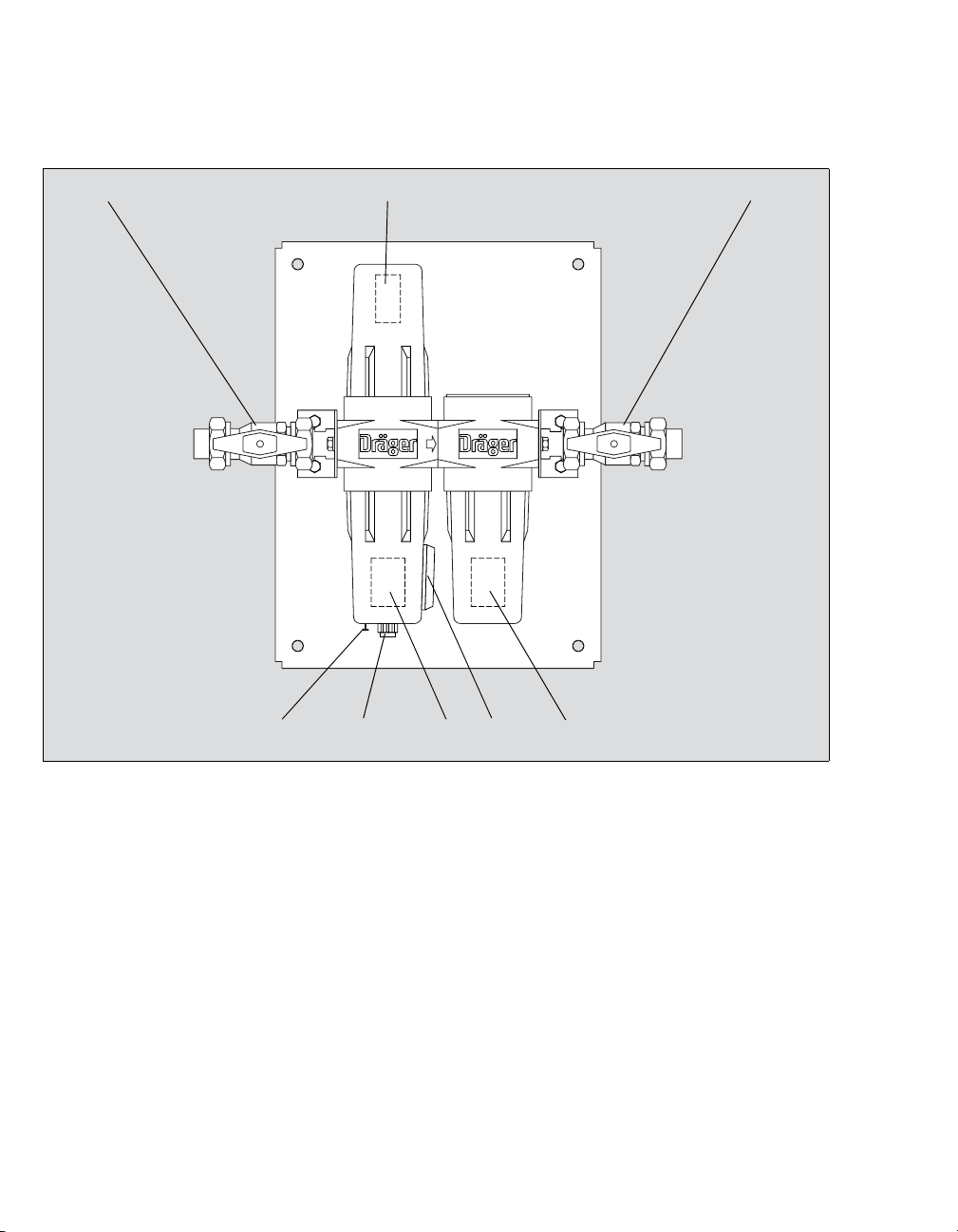
Instructions for use Air filter station 60/190 Pressure-reducing station 100/300 7
For your safety and that of your patients
General safety information
The following WARNING and CAUTION
statements apply to general operation of the
medical device.
WARNING or CAUTION statements specific to
subsystems or particular features of the medical
device appear in the respective sections of these
Instructions for use or in the Instructions for use of
another product being used with this device.
Strictly follow these Instructions for Use
Maintenance
Not for use in areas of explosion hazard
WARNING
Any use of the medical device requires full
understanding and strict observation of all
sections of these instructions for use. The
medical device must only be used for the
purpose specified under "Intended use"
on page 8. Strictly observe all WARNING and
CAUTION statements throughout these
Instructions for use and all statements on
medical device labels. Failure to observe
these safety information statements
constitutes a use of the medical device that is
inconsistent with its intended use.
WARNING
The medical device must be inspected and
serviced regularly by professionals who
possess the required qualifications due to
their training and their experience. Repair of
the medical device must also be performed by
trained personnel with additional product-
specific DrägerService training.
Dräger recommends that a service contract is
obtained with DrägerService for all repairs.
Dräger recommends that only authentic
Dräger parts be used for maintenance.
If the above are not complied with, the correct
functioning of the medical device may be
compromised.
See chapter "Maintenance".
WARNING
This medical device is neither approved nor
certified for use in areas where combustible or
explosive gas mixtures are likely to occur.

Use
8 Instructions for use Air filter station 60/190 Pressure-reducing station 100/300
Use
Intended use
Air filter station
Filter station to filter coarse particles (including oil
and water drops), oil vapor content, and fine dust
from compressed air for ventilation and technical
use.
If the air filter station is used as an additional filter
station, then the air filter station is also approved for
use in compressed air systems for medical
compressed air.
Pressure-reducing station
Pressure-reducing station to reduce the system
pressure of compressed air systems to operational
pressure for ventilation and for the use of surgical
instruments.
The pressure-reducing station has been approved
for use in compressed air systems for medical
compressed air.

Instructions for use Air filter station 60/190 Pressure-reducing station 100/300 9
Overview
Overview
Air filter station
The air filter station features 3 filter levels:
– 1st filter level (fine filter):
Separation of oil and water drops (aerosols)
– 2nd filter level (activated charcoal filter):
Adsorption of oil from the vapor phase using
activated charcoal
– 3rd filter level (HEPA filter):
Filtration of bacteria

Overview
10 Instructions for use Air filter station 60/190 Pressure-reducing station 100/300
Air filter station 60
ABall valve input
BActivated charcoal filter (2nd filter level)
CBall valve output
DHEPA filter (3rd filter level)
EFluid fill level display
FFine filter (1st filter level)
GConnection for condensate discharge
HOperation control and relief valve
030
ABC
FED
HG

Instructions for use Air filter station 60/190 Pressure-reducing station 100/300 11
Overview
Air filter station 190
ABall valve input
BTest and relief valve
CBall valve output
DActivated charcoal filter (2nd filter level) and
HEPA filter (3rd filter level)
EFluid fill level display
FFine filter (1st filter level)
GConnection for condensate discharge
031
ABC
ED
GF

Overview
12 Instructions for use Air filter station 60/190 Pressure-reducing station 100/300
Pressure-reducing station
Pressure reduction from approx. 11 bar to 15 bar
inlet pressure to:
– 5 bar outlet pressure for ventilation
or
– 8 bar outlet pressure for surgical instruments
The pressure-reducing station 100 and
pressure-reducing station 300 are of analog
design.
The pressure-reducing stations have 2 redundantly
arranged pressure reducers each.
This allows maintenance work to be conducted on
one pressure reducer without interrupting
operation.

Instructions for use Air filter station 60/190 Pressure-reducing station 100/300 13
Overview
Pressure-reducing station 100/5 bar
AInlet screw connection
for optional reserve supply from a cylinder bank
system
BPressure reducer
CCable clip
DConnection terminal
EPrimary strand 5 bar
FSafety valve
GSoldered outlet connection 5 bar
HContact pressure gauge cable 5 bar
IContact pressure gauge 5 bar
JEmergency inlet and sampling port (NIST
connection)
KRedundant 5-bar line
LExtension screw connection
for pressure-reducing station 100/8 bar
MSoldered inlet connection
for compressed air system
101
ABCDEF
M
G
J
K
H
I
L

Overview
14 Instructions for use Air filter station 60/190 Pressure-reducing station 100/300
Pressure-reducing station 100/8 bar
AInlet screw connection
for a pressure-reducing station 100/5 bar or a
compressed air system for supplying surgical
instruments
BPressure reducer
CCable clip
DConnection terminal
EPrimary strand 8 bar
FSafety valve
GSoldered outlet connection 8 bar
HContact pressure gauge cable 8 bar
IContact pressure gauge 8 bar
JSampling port (NIST connection)
KSampling port label
LRedundant 8-bar line
102
ABCDEF
G
J
K
H
I
L
NOTE
The sampling port of the pressure-reducing
station 100/8 bar is only used for sampling for the
quality control of the medical compressed air and
not for the emergency supply of a compressed air
system.
The NIST connection is identical to the NIST
connection of the pressure-reducing
station 100/5 bar.

Instructions for use Air filter station 60/190 Pressure-reducing station 100/300 15
Overview
Pressure-reducing station 300/5 bar
APressure reducer
BCable clip
CConnection terminal
DPrimary strand 5 bar
ESafety valve
FSoldered outlet connection 5 bar
GContact pressure gauge cable 5 bar
HContact pressure gauge 5 bar
IEmergency inlet and sampling port (NIST
connection)
JRedundant 5-bar line
KExtension screw connection
for pressure-reducing station 300/8 bar
LSoldered inlet connection
for compressed air system
103
ABCDE
L
F
I
J
G
H
K

Overview
16 Instructions for use Air filter station 60/190 Pressure-reducing station 100/300
Pressure-reducing station 300/8 bar
AInlet screw connection
for a pressure-reducing station 300/5 bar or a
compressed air system for supplying surgical
instruments
BPressure reducer
CCable clip
DConnection terminal
EPrimary strand 8 bar
FSafety valve
GSoldered outlet connection 8 bar
HContact pressure gauge cable 8 bar
IContact pressure gauge 8 bar
JSampling port (NIST connection)
KSampling port label
LRedundant 8-bar line
104
ABCDEF
G
J
L
H
I
K
NOTE
The sampling port of the pressure-reducing
station 300/8 bar is only used for sampling for the
quality control of the medical compressed air and
not for the emergency supply of a compressed air
system.
The NIST connection is identical to the NIST
connection of the pressure-reducing
station 300/5 bar.

Instructions for use Air filter station 60/190 Pressure-reducing station 100/300 17
Overview
Implementation examples
Pressure-reducing station 100/5 bar and
100/8 bar
The pressure-reducing station 100/5 bar can be
combined with the pressure-reducing
station 100/8 bar.
Pressure-reducing station 300/5 bar and
300/8 bar
The pressure-reducing station 300/5 bar can be
combined with the pressure-reducing
station 300/8 bar.
110
111

Overview
18 Instructions for use Air filter station 60/190 Pressure-reducing station 100/300
Abbreviations
:
Symbols
Abbreviation Explanation
DIN Deutsches Institut für Normung
(German Institute for
Standardization)
EEC European Economic Community
EN European Standard
ISO International Organization for
Standardization
NIST Non-Interchangeable Screw
Thread
UMDNS Universal Medical Device
Nomenclature System
Symbol Explanation
Disposal information
Manufacturer
Observe Instructions for Use

Instructions for use Air filter station 60/190 Pressure-reducing station 100/300 19
Assembly
Assembly
Air filter station
Pipe connections are not included with the delivery.
zConnect air filter stations in parallel.
Connection example:
1Position the base plate (A) in accordance with
the requirements on site.
2Mark the drill holes of the base plate (A) on the
wall.
3Drill the holes.
4Insert the wall anchors.
042
Air filter station 60
A
B
D
C
B
F
E
E
F
A
D
C
043
NOTE
Select the wall anchors in accordance with the wall
design and the weight of the air filter station.
Observe the assembly instructions of the wall
anchor manufacturer.
Air filter station 190
A
B
C
A
B
C
D
D
E
E
F
F

Assembly
20 Instructions for use Air filter station 60/190 Pressure-reducing station 100/300
5Screw the base plate (A) to the wall.
6Connect the soldered inlet connections (F) to
the piping network.
7Connect the soldered outlet connections (B) to
the piping network.
8Connect the line for condensate drain to (D).
For air filter station 60:
ISO 228/1–G 1/8 / G 1/4 connection
For air filter station 190:
ISO 228/1–G 1/8 connection
9Place air filter station under operating pressure:
To do so:
10 Slowly open all ball valves (E) at the input.
11 Slowly open all ball valves (C) at the output.
12 Then test all connection points for leaks using a
leak detection agent.
13 Close are ball valves at the input (E) and at the
output (C).
This manual suits for next models
5
Table of contents
Other Dräger Water Filtration System manuals
Popular Water Filtration System manuals by other brands

Acuva
Acuva Arrow 5 Owner's Product Manual

Bartscher
Bartscher 109881 instruction manual

Watts
Watts PWSYS-FIL-ICE3 Installation and operation manual

Aquafine
Aquafine RBE Series Installation, maintenance and operation manual

Sartorius
Sartorius arium 611VF Installation and operation manual

Kenwood
Kenwood WF900 quick start guide