Dr.X Works Statera 15/100 User manual


Contents
1 Introduction 4
2 Installation 5
2.1 Unpacking and inspection . . . . . . . . . . . . . . . . . . . . . . . . . . . . 5
2.2 Connections and controls . . . . . . . . . . . . . . . . . . . . . . . . . . . . 5
2.3 powerrequirements................................ 5
3 Operation 6
4 Technical specification 9
4.1 Electrical ..................................... 9
4.2 Mechanical .................................... 9
5 Environmental 10
6 Maintenance 11
7 Safety 12
8 Warranty 13
9 Mechanical outline 14
A Software control 15
Statera 15/100 version 1.1 3

1. Introduction
The Statera 15/100 is a microwave driver for a resonant radio frequency (RF) cavity.
The driver respectively offers up to 15W/75W of RF output power. The transmitted
and reflected output power are continuously monitored and displayed on the device. The
driver stabilizes the phase and amplitude of the fields in the cavity which results in optimal
performance. The driver measures the actual fields in the cavity and compares these both
in phase and amplitude with the signal that is offered to the driver. Both the phase and
amplitude are then stabalized using loop electronics. The phase and amplitude errors can
be monitored on a scope. The driver also allows to control the phase and amplitude directly
on the device or via a remote connection (usb/ethernet).
Statera 15/100 version 1.1 4

2. Installation
2.1 Unpacking and inspection
1. After installation into 19”-rack or other, connect mains cable to the back panel.
2. Connect the DSUB-9 cable to the cooler output (the other end goes to the printed
circuit board that has to be connected to the chiller)
3. Connect the RF drive cable to the power output (the other end goes to the RF drive
input of the cavity)
4. Connect the phase stable sma cable to the pickup probe input on the statera (the
other end goes to the pickup probe output of the cavity). When there is an attenu-
tator present on the phase stable pickup cable make sure that the attenuator side of
the cable is connected to the statera.
5. Connect an SMA cable to the RF input (make sure that the input signal does not
exceed +10 dBm and that the frequency matches the cavity resonant frequency)
2.2 Connections and controls
In the table below the inputs and outputs are summarized.
RF input Input SMA max +10 dBm RF input
Pickup probe Input SMA signal from cavity
I Output BNC output of the IQ demodulator
Q Output BNC output of the IQ demodulator
Power output Output N type 0-15W RF output
Cooler Input/Output DSUB-9 Interlock and communication chiller
Ethernet Input/Output RJ45 remote control over ethernet
USB Remote Input/Output USB-B remote control over USB
USB Firmware Input/Output USB-B firmware update over USB
Mains power Input Euroconnector 110 or 230 V (auto switching)
2.3 power requirements
The current source operates on single phase AC mains power from 100 V to 240V with a
frequency between 47 and 63 Hz without any need for range selection. The primary fuses
are 6.3AT.
Statera 15/100 version 1.1 5

3. Operation
Figure 3.1 shows the main screen of the Statera 100. The Local knob shows if the
device is in local or remote mode. Pressing this button opens up a new window that gives
the device information. The power switch can be used to enable the RF output of the
Statera. The output is automatically turned of in the following cases:
1. Chiller has fault
•cooler cable not connected
•chiller turned off
•no water flowing
•temperature limit
2. Transmitted power >75.0W
3. Reflected power >20.0W
Figure 3.1: Main screen of Statera 100
Statera 15/100 version 1.1 6

CHAPTER 3. OPERATION
Below the power switch you find the control over the feedback loop. The phase knob
can be used to reset the phase feedback in case that is has unlocked. The colour of the text
on the phase knob shows if the phase is correctly locked or not. When the text ”Phase”
appears in green than the phase is correctly locked. In case the text appears in red the
phase should be reset by the user by simply pressing the button. The amplitude switch
below the phase feedback knob can be used to turn the amplitude feedback function on
and off. Please note that the power can only be controlled when the amplitude feedback is
turned on. The user sets the power setpoint and the loop electronics will adjust the power
to reach the setpoint, in case the amplitude feedback loop is turned off the power will thus
not be changed.
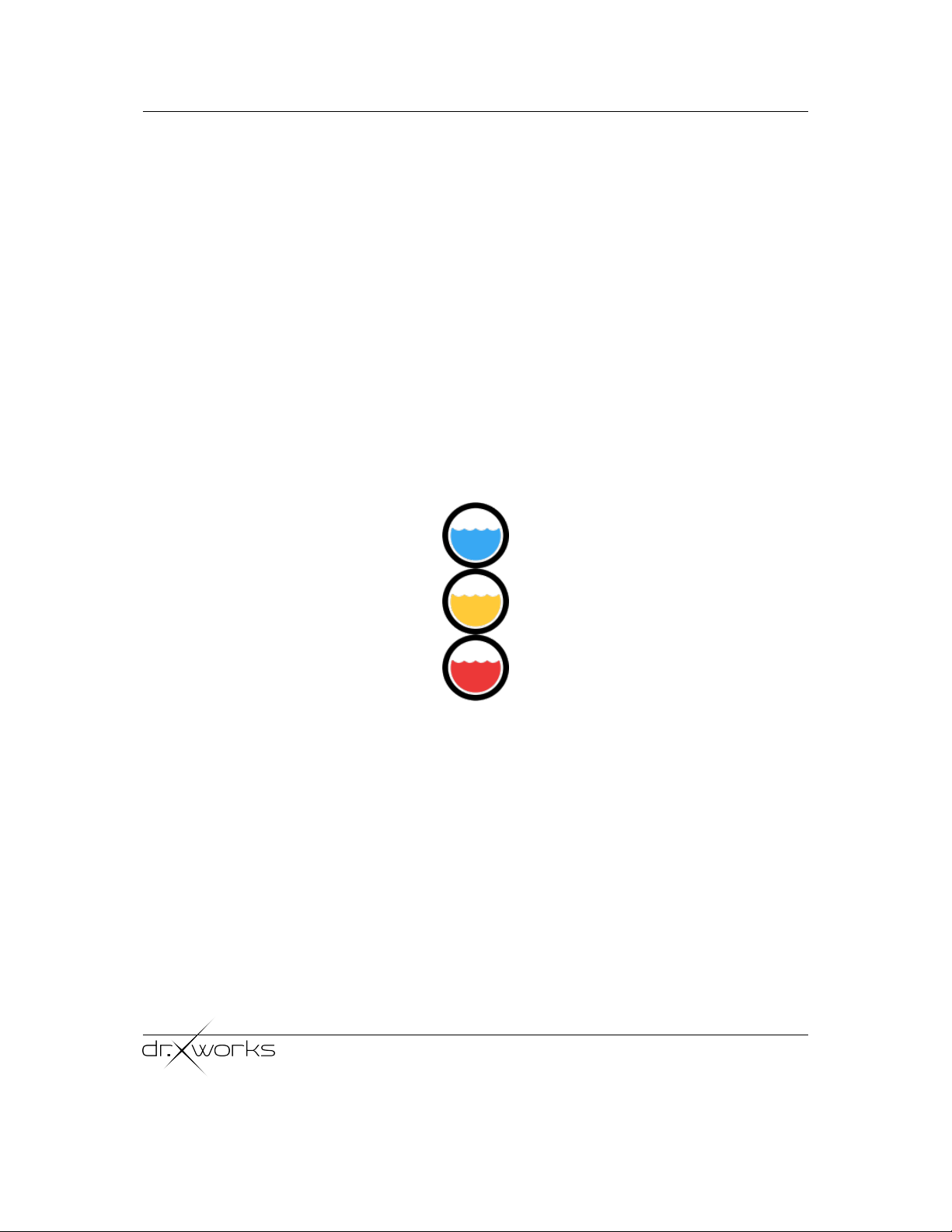
The chiller icon, see figure 3.2, can have three colours. Red means that the chiller has
an error. Yellow means that the chiller is operating Ok but that the cavity temperature is
not equal to the temperature setpoint. Blue means that the cavity temperature is equal to
the temperature setpoint. The cooler icon can also be pressed to open the cooler window
that shows the temperature setpoint, the cavity to which this setpoint belongs, and an
graph of the temperature as a function of time.
Figure 3.2: Different states of cooler icon
Right to the chiller icon the transmitted power graph is shown. This graph shows the
amount of power transmitted to the cavity. The actual value is also printed in text (blue)
on top of the graph. The red text displays the reflected power. This value should be as
small as possible. When increasing the RF output power the cavity will start to warm
up, the chiller icon will become yellow. The heating of the cavity will cause the resonant
frequency to shift which means that the reflected power will increase. It will take some
time for the chiller to find a new equilibrium and you will see that the reflected power will
decrease over time. In steady state (blue chiller icon) the reflected power should be smaller
then 5 percent of the transmitted power. For example when 10.0 W is transmitted the
reflected power in steady state should be <0.5 W.
The phase and power dials on the top are used to control the output. These values can
be changed by either using the touch screen or by rotating the physical rotary knob on the
Statera 15/100 version 1.1 7

CHAPTER 3. OPERATION
front of the Statera. The knob becomes responsive only when a control is selected which
can be done by pressing the phase or power number on the touchscreen.
Statera 15/100 version 1.1 8

4. Technical specification
4.1 Electrical
The Statera 15/100 is mounted in an EMC enclosure.
Central Frequency 2998.5 MHz
Frequency range +/- 20 MHz
Power output 0-15W (Statera 15) or 0-75W (Statera 100)
RF input max +10dBm at resonant frequency of cavity
Cooler DSUB-9 communication cable to chiller
Power Supply Mains 80-130V for 60 Hz or 180-250V for 50 Hz
4.2 Mechanical
Dimensions (LHW) 19” x 3U x 350mm
Weight ca. 25kg
Statera 15/100 version 1.1 9

5. Environmental
Operating temperature range 0 to 40◦C ambient, however temperature fluctuations should
be kept as small as possible to prevent drifting. The Statera 15/100 should be operated in
a clean environment. On no account must the Statera 15/100 be exposed to water ingress.
Statera 15/100 version 1.1 10

6. Maintenance
No maintenance is required in normal operation and there are no user-serviceable parts
within the Statera 15/100. Each product is factory tested and supplied with a set of test
results. If degradation in performance to below the specified levels occurs, or a failure is
suspected, then the complete unit should be returned to the manufacturer together with
details of the fault.
Statera 15/100 version 1.1 11

7. Safety
Hazardous voltages are present within this line-operated unit. Do not remove any panels.
The Statera 15/100 must be grounded. Line supply is filtered within the amplifier. A
replaceable fuse is fitted to the line input connector which should be changed only when
the AC power is disconnected from the connector.
Statera 15/100 version 1.1 12

8. Warranty
Dr.X Works B.V. warrants for 2 years from date of shipment that the goods supplied will be
in full compliance with the agreed specifications and will be free from defects in material and
workmanship. Any and all other warranties (except of title) express or implied, relating to
fitness for particular purpose, merchantable quality or otherwise are expressly disclaimed.
Seller will not be responsible for special or consequential loss or damages. Liability shall
be limited to the repair or replacement of defective products subject to the return of the
product intact, and un-tampered with by the buyer.
Statera 15/100 version 1.1 13

9. Mechanical outline
100W MICROWAVE DRIVER
Statera 100
max +10 dBm
Pickup
antenna
Manual
Monitor
I
Q
RF Seed
USB
Power Output
Input Cooler
Ethernet
Voltage
100-240 VAC
Fuses
2x 6.3AT
Control
Firmware update
Statera 15/100 version 1.1 14

A. Software control
Protocol
The device can be controlled either over USB or over Ethernet. The Statera USB in-
terface makes use of a HID device which means that no drivers need to be installed.
The communication protocol is as follows: packets of 8 bytes are used to communicate
with the device. The eight bytes are arranged as follows:
f0f1f2= or ? x0x1x2x3
The first three bytes consist of three ASCII command characters that select feature (f0-
f2) to be controlled. Note that these are case sensitive. Thereafter a (? or =) ASCII
character is used to respectively get or set the value of the selected control. The last
four bytes contain the value that will be set or get. The last four bytes (x0-x3) need
to be casted to an Little Endian Float (4 bytes DCBA) to either set or retrieve the
value.
As an example the following command sets the device into remote mode which has to
be done before any other commands are accepted: Rem=1 where the value 1
has to be casted to a four byte little endian float.
ASCII R e m = \0\0e?
Hex 0x52 0x65 0x6D 0x3D 0x00 0x00 0x80 0x3F
When connection to the device over ethernet the following command has to be send
prior to setting the device into remote mode otherwise the TCP connection will
be automatically shut down. Rem=SN where SN is the 7 digit device serial number.
For example when the serial number X= 7021134 the message is as follows:
ASCII R e m = œ D ¨
O J
Hex 0x52 0x65 0x6D 0x3D 0x9C 0x44 0xD6 0x4A
After every message the device returns a similar eight byte message with the response.
The first two bytes in the response show the status. This can either be ”Ok” (in case
everything went alright)
ASCII O k \0\0 value (4 byte )
Hex 0x4F 0x6B 0x00 0x00 data
or ”Er” (in the case of an error).
Statera 15/100 version 1.1 15

APPENDIX A. SOFTWARE CONTROL
ASCII E r \0\0 value (4 byte )
Hex 0x45 0x72 0x00 0x00 data
The first two bytes are followed by two null characters whereafter the value is printed.
The value again needs to be typecasted to a little endian float. In the case of a
read/write command that was successfully processed (”Ok”) the returned value will
contain the most current value of the feature which should be equal to the value that
is set. This does not hold when you exceed the setpoint limit, e.g. when you try to
set the RF power using the ”Pow” command to 999.0 the return value will be 100.0
since the power cannot be set to 999.0. All the available commands are listed below.
In the case of an error the four byte return value represents the error code, below you
can find what the meaning of the error codes are.
Commands (f0-f2) - Read/Write - Case Sensitive !
Rem remote mode (0 or 1)
Pha phase between 0 and 100
Pow power between 0 and 100
Swi power switch (0 or 1)
Commands (f0-f2) - Read Only - Case Sensitive !
Ref Reflected power
Tra Transmitted power
Tem Cavity Temperature (measured by Pt100) in deg Celsius
Pfe phase feedback enable (0 or 1)
Afe Amplitude feedback enable (0 or 1)
Statera 15/100 version 1.1 16

APPENDIX A. SOFTWARE CONTROL
Error codes
1 Device is in Ethernet Remote
2 Device is in USB remote
3 Error adding message to Queue
4 Error in receive queue
5 Queue is invalid
6 Error updating device
7 Error reading feature value
8 Command is invalid (first three bytes)
9 Read/write character unknown (byte number four)
10 Device is not in remote so cannot process command
11 Error unknown
12 Error remote check
13 Feature not enabled on device
123456 Error invalid SN when connecting over ethernet
Statera 15/100 version 1.1 17
Table of contents
Popular Portable Generator manuals by other brands

Honda
Honda EB10000 owner's manual

Craftsman
Craftsman CMXGGAS030729 Operator's manual

Ritelite
Ritelite RITE-POWER 1750 Operator's manual

Briggs & Stratton
Briggs & Stratton 030635A-00 Wiring diagram

GÜDE
GÜDE GSE 6701 RS Translation of the original instructions

Powermate
Powermate PMA525302.01 owner's manual