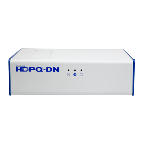
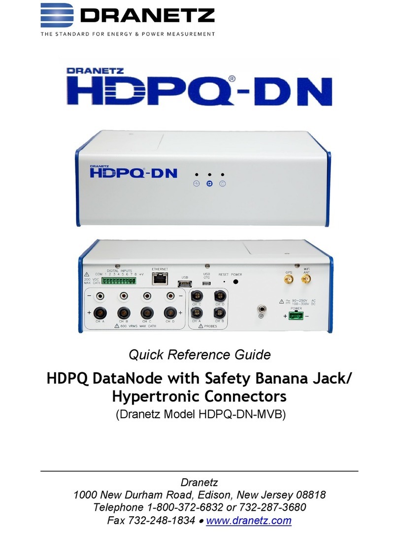
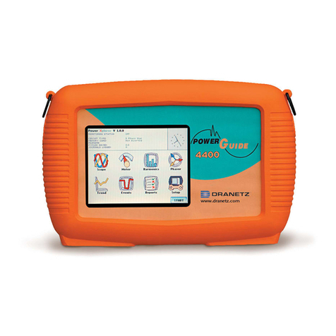
Dranetz HDPQ-DN-MZP User manual

Quick Reference Guide
HDPQ DataNode with Voltage/Current Pod Connectors
(Dranetz Model HDPQ-DN-MZP)
Dranetz
1000 New Durham Road, Edison, New Jersey 08818
Telephone 1-800-372-6832 or 732-287-3680
Fax 732-248-1834
www.dranetz.com

2
WARNING
Death, serious injury, or fire hazard could result from improper
connection of this instrument. Read and understand this manual before
connecting this instrument. Follow all installation and operating
instructions while using this instrument.
Connection of this instrument must be performed in compliance with the
National Electrical Code (ANSI/NFPA 70-2017) of USA and any
additional safety requirements applicable to your installation.
Installation, operation, and maintenance of this instrument must be
performed by qualified personnel only. The National Electrical Code
defines a qualified person as “one who has the skills and knowledge
related to the construction and operation of the electrical equipment and
installations, and who has received safety training on the hazards
involved.”
Qualified personnel who work on or near exposed energized electrical
conductors must follow applicable safety related work practices and
procedures including appropriate personal protective equipment in
compliance with the Standard for Electrical Safety Requirements for
Employee Workplaces (ANSI/NFPA 70E-2015) of USA and any
additional workplace safety requirements applicable to your installation.
Published by Dranetz
1000 New Durham Road
Edison, NJ 08818-4019 USA
Telephone: 1-800-372-6832 or 732-287-3680
Fax: 732-248-1834
Website: www.dranetz.com
Copyright ©2019 Dranetz
All rights reserved.
No part of this book may be reproduced, stored in a
retrieval system, or transcribed in any form or by any
means—electronic, mechanical, photocopying, recording,
or otherwise—without prior written permission from the
publisher, Dranetz, Edison, NJ 08818-4019.
Printed in the United States of America.
P/N QR-HDPQ-DN-MZP Rev. D 04.04.19

3
ADVERTENCIA
Una conexión incorrecta de este instrumento puede producir la muerte,
lesiones graves y riesgo de incendio. Lea y entienda este manual antes de
conectar. Observe todas las instrucciones de instalación y operación durante
el uso de este instrumento.
La conexión de este instrumento a un sistema eléctrico se debe realizar en
conformidad con el Código Eléctrico Nacional (ANSI/NFPA 70-2017) de los
E.E.U.U., además de cualquier otra norma de seguridad correspondiente a
su establecimiento.
La instalación, operación y mantenimiento de este instrumento debe ser
realizada por personal calificado solamente. El Código Eléctrico Nacional
define a una persona calificada como "una que esté familiarizada con la
construcción y operación del equipo y con los riesgos involucrados."
El personal cualificado que trabaja encendido o acerca a los conductores
eléctricos energizados expuestos debe seguir prácticas y procedimientos
relacionados seguridad aplicable del trabajo incluyendo el equipo protector
personal apropiado en conformidad con el estándar para los requisitos de
seguridad eléctricos para los lugares de trabajo del empleado (ANSI/NFPA
70E-2015) de los E.E.U.U. y cualquier requisito de seguridad adicional del
lugar de trabajo aplicable a su instalación.
AVERTISSEMENT
Si l'instrument est mal connecté, la mort, des blessures graves, ou un
danger d'incendie peuvent s'en suivre. Lisez attentivement ce manuel avant
de connecter l'instrument. Lorsque vous utilisez l'instrument, suivez toutes
les instructions d'installation et de service.
Cet instrument doit être connecté conformément au National Electrical Code
(ANSI/NFPA 70-2017) des Etats-Unis et à toutes les exigences de sécurité
applicables à votre installation.
Cet instrument doit être installé, utilisé et entretenu uniquement par un
personnel qualifié. Selon le National Electrical Code, une personne est
qualifiée si "elle connaît bien la construction et l'utilisation de l'équipement,
ainsi que les dangers que cela implique".
Le personnel qualifié qui travaillent dessus ou s'approchent des conducteurs
électriques activés exposés doit suivre des pratiques en matière et des
procédures reliées par sûreté applicable de travail comprenant le matériel de
protection personnel approprié conformément à la norme pour des
conditions de sûreté électriques pour les lieux de travail des employés
(ANSI/NFPA 70E-2015) des Etats-Unis et toutes les conditions de sûreté
additionnelles de lieu de travail applicables à votre installation.
4
WARNUNG
Der falsche Anschluß dieses Gerätes kann Tod, schwere Verletzungen oder
Feuer verursachen. Bevor Sie dieses Instrument anschließen, müssen Sie
die Anleitung lesen und verstanden haben. Bei der Verwendung dieses
Instruments müssen alle Installation- und Betriebsanweisungen beachtet
werden.
Der Anschluß dieses Instruments muß in Übereinstimmung mit den
nationalen Bestimmungen für Elektrizität (ANSI/NFPA 70-2017) der
Vereinigten Staaten, sowie allen weiteren, in Ihrem Fall anwendbaren
Sicherheitsbestimmungen, vorgenommen werden.
Installation, Betrieb und Wartung dieses Instruments dürfen nur von
Fachpersonal durchgeführt werden. In dem nationalen Bestimmungen für
Elektrizität wird ein Fachmann als eine Person bezeichnet, welche "mit der
Bauweise und dem Betrieb des Gerätes sowie den dazugehörigen Gefahren
vertraut ist."
Qualifiziertes Personal, das an bearbeiten oder herausgestellte angezogene
elektrische Leiter sich nähern, muß anwendbare Sicherheit bezogener Arbeit
Praxis und Verfahren einschließlich passende persönliche schützende
Ausrüstung gemäß dem Standard für elektrische Sicherheitsauflagen für
Angestellt-Arbeitsplätze (ANSI/NFPA 70E-2015) der Vereinigten Staaten und
alle zusätzlichen Arbeitsplatzsicherheitsauflagen folgen, die auf Ihre
Installation anwendbar sind.
Safety Summary
Definitions
WARNING statements inform the user that certain conditions or
practices could result in loss of life or physical harm.
CAUTION statements identify conditions or practices that could harm the
instrument, its data, other equipment, or property.
NOTE statements call attention to specific information.
Symbols
The following International Electrotechnical Commission (IEC) symbols
are marked on the top and rear panel in the immediate vicinity of the
referenced terminal or device:

5
Caution, refer to accompanying documents (this manual).
Alternating current (AC) operation of the terminal or device.
Direct current (DC) operation of the terminal or device.
Safety Precautions
The following safety precautions must be followed whenever any type of
voltage or current connection is being made to the instrument.
• Connect the safety (earth) ground first, before making any other
connections.
• When connecting to electric circuits or pulse initiating equipment,
open their related breakers. DO NOT install any connection of the
instrument on live power lines.
• Connections must be made to the instrument first, then connect to the
circuit to be monitored.
• Wear proper personal protective equipment, including safety glasses
and insulated gloves when making connections to power circuits.
• Hands, shoes and floor must be dry when making any connection to a
power line.
• Make sure the instrument is turned OFF before connecting probes to
the rear panel.
• Before each use, inspect all cables for breaks or cracks in the
insulation. Replace immediately if defective.
• If the equipment is used in a manner not specified in this reference
guide, the protection provided by the equipment may be impaired.
These safety precautions are repeated where appropriate throughout
this manual.

6
TABLE OF CONTENTS
Introduction…………………………………………….…… 7
This Quick Reference Guide……….….………...………… 7
Getting Started……………………………………………... 8
Connecting to Power Source…..………………...………... 8
Controls, Indicators and Connectors….………...………… 10
Reset to Factory Defaults…..…..………………...………... 12
Connecting to the HDPQ DataNode………………………. 13
Connecting via Wired Ethernet Connection………………. 14
Connecting via Wireless (WiFi) Connection……………… 16
HDPQ IP Setup Program...……………………...…………. 18
Making Measurement Connections…………………….. 21
Connecting the Voltage and Current Input Pods.….….... 22
Connecting the Input Pods to the HDPQ DataNode….... 24
Single Phase.………….…………………………………….. 26
Split Phase.……………………………..…….……......……. 27
3 Phase Four Wire Wye…………………………………….. 28
3 Phase (Floating or Grounded) Delta …….……......……. 29
3 Phase 2-Watt Delta ...…………………………………….. 30
2 1/2 Element Without Voltage Channel B …….......……. 31
2 1/2 Element Without Voltage Channel C …….......……. 32
Accessories List…..……………………….………………. 33
Standard Accessories………….………………………...…. 33
Optional Accessories………….………….……………...…. 33
Digital Inputs HDPQ-DN-MDIN (optional)………….….. 34
Connecting to Digital Inputs………….………….………… 34
General Specifications…..…………………………….….. 36
Statements and Notices….……………………………….. 37

7
INTRODUCTION
The Dranetz HDPQ DataNode - Model MZP, also called HDPQ-DN-MZP,
is an eight-channel power quality and energy instrument that can be
installed in a permanent or temporary installation. All user interactions
are performed remotely by using compatible server software, either
through a wired Ethernet or Wireless (WiFi) (optional) connection. The
HDPQ-DN-MZP can monitor and record data on four voltage channels
as well as four current channels simultaneously.
Dranetz HDPQ-DN-MZP is designed to meet both the IEEE 1159 and
IEC 61000-4-30 Edition 3 Class A standards for accuracy and
measurement requirements. It can do PQ-optimized acquisition of power
quality related disturbances and events. Compliance standards such as
EN50160 are also supported.
The HDPQ-DN-MZP allows you to customize threshold settings for
power quality, energy and demand. It can monitor power quality and
energy/demand phenomena for troubleshooting and/or compliance
purposes. It can also record inrush conditions, carry out long-term
statistical studies to establish performance baselines, and perform field-
based equipment testing and evaluation for commissioning and
maintenance. The HDPQ-DN-MZP firmware integrates an intuitive
instrument setup procedure to ensure the capture of all relevant data for
additional post process analysis, report writing, and data archiving using
the Dranetz PQView®DE or PQView®web-enabled applications.
This Quick Reference Guide
This Quick Reference Guide contains instructions for the basic operation
of the Dranetz HDPQ DataNode - Model MZP with Voltage/Current Pod
connectors. Other models are available that support different types of
physical circuit connections.

8
GETTING STARTED
Connecting to Power Source
Power
Specifications
CAUTION
PRECAUCION
MISE EN
GARDE
The power supply inputs are rated 90–250 VAC 50/60
Hz and 100-300 VDC. A screw terminal block is used
to connect up to #12 AWG gauge wire for the power
input connections. The positive and negative inputs
are fused internally and the fuses are not user-
replaceable.
Operation of the HDPQ DataNode from a voltage
source other than the rated voltage input stated
on the unit nameplate can cause damage to the
unit.
La operación del HDPQ DataNode desde una
fuente de voltaje de ca que no sea la entrada de
voltaje nominal indicada en la placa de
identificación de la unidad puede causar daños a
la unidad.
Le fonctionnement du HDPQ DataNode à partir
d'une source de tension alternative autre que
l'entrée de tension nominale indiquée sur la
plaque signalétique de l'unité peut endommager
l'unité.
VORSICHT
Der Betrieb des HDPQ DataNode von einer
Wechselspannungsquelle, die nicht dem auf der
Namensplatte der Einheit aufgeführten
Nennspannungseingang entspricht, kann
zur Beschädigung der Einheit führen.

9
Safety
Disconnects
WARNING
The mains supply power to the HDPQ DataNode
must be installed downstream from a switched
current limiting device. The circuit protection
device should be 20 Amps or less, and must be
rated for the available voltage and fault current; 5
Amps fuses are preferred.
All mains supply conductors connected to the
HDPQ DataNode must originate at circuit breakers
or fuses rated 20 Amps or less.
You must provide a method for manually
removing power from the HDPQ DataNode such as
a clearly labeled circuit breaker or a fused
disconnect switch.
The AC/DC power input is found at the rear panel of the unit. The rear
panel for DataNode Model HDPQ-DN-MZP is shown below.
Power Source
The rear panel marking provides information about the
input power rating.
• Voltage range: 90-250 VAC, 100-300 VDC
• Frequency: 50/60 Hz.
• Power Consumption: 25 W.
Step Action
1 With all power OFF, connect the green ground wire to Safety
(Earth) ground first before making any other connections.
2 Connect the positive (+) terminal of the mains supply to the
positive (+) terminal of the instrument, AC or DC using the
appropriate color coding and wire up to #12 AWG wire.
3 Connect the negative (-) terminal of the mains supply to the
negative (-) terminal of the instrument, AC or DC using the
appropriate color coding and wire up to #12 AWG wire.
4 Turn the power switch of the instrument to ON position.

10
Controls, Indicators and Connectors
Top View and Front View
Top Panel
The top panel shows the user replaceable Battery compartment.
Internal Battery
Sealed, rechargeable NiMH (Nickel Metal Hydride) cell
The unit will always operate on the normal power
source 50/60Hz, 90-250VAC or 100-300VDC. In the
event of loss of power, the unit will seamlessly
switch to the internal battery backup and will switch
back to the normal power source when restored.
Front Panel
The front panel shows the following three (3) LED indicators:
Status Indicator
Monitoring On
Indicator
LED will blink in a heartbeat fashion when power
switch is turned on and the unit is operating normally.
LED will light steadily if monitoring is on. Monitoring
is off when light is off.
Battery Indicator
LED will light steadily when operating on battery
backup.

11
Rear View
This section describes the rear view panel of the HDPQ-DN-MZP.
Digital Input (optional) – use to monitor on/off-type digital
signals, such as breaker or switch position indicators.
Ethernet Port – use to connect a wired Ethernet (RJ45) network.
An Ethernet cross over cable may be required to connect directly
to a computer when not using a network.
USB/Micro-USB Port – use for file transfer to a USB flash drive or
directly to a computer.
Reset Button –use to reset the instrument settings to factory
defaults. See section Reset to Factory Defaults for details on how
to manually reset the instrument to factory configuration.
Power Switch – use to turn unit power on or off. Power indicator
lamp on front panel flashes when unit is on.
IRIG-B Input (optional) – use as external time sync signal.
GPS Port (optional) – input for GPS antenna for time sync.
WiFi Antenna (optional) – use for wireless connectivity via a
factory-installed WiFi card (not user installable).
Power Input – use to connect AC/DC power.
Voltage/Current Input Connectors – use to connect voltage/
current pod via an interface cable. See section Connecting the
Voltage and Current Input Pods for circuit connection details.
1
2
3
4
5
6
8
9
10
7
1
2
3
4
6
7
8
9
10
5

12
Reset to Factory Defaults
Resetting the instrument to factory defaults will erase all user data,
communication settings, including recorded logs and events, reports and
instrument setup files.
The steps below show how to manually reset the HDPQ DataNode to
factory configuration.
NOTE: The reset button is recessed and can be found at the rear panel
of the instrument. A paper clip, pin or similar item is needed to
press in the reset button.
Step Action
1 Unfold the paper clip to form at least a 1-inch long straight
line wire.
2 Gently insert the paper clip (or other tool) into the “Reset”
button hole at the rear panel of the HDPQ DataNode.
Press in the internal reset button and hold for ten (10)
seconds.
Continue to hold until the Status LED indicator at the front
panel stops blinking which indicates that the reset and reboot
process has been initiated. If you let go before 10 seconds,
the unit will reboot but it will not reset.
3 Once reboot is completed, the Status LED indicator will blink
in a heartbeat fashion to indicate that the unit has returned to
normal operation.
At this point, the instrument has been reset to factory
configuration, including the following default connection
settings:
Default User name: admin
Default Password: Dranetz
Wired Ethernet IP address will be fixed at 192.168.0.30.
NOTE: All saved data and setups will be lost when you reset
the instrument settings to factory defaults.

13
Connecting to the HDPQ DataNode
PQView® DE is web-enabled server software that serves as the primary
user interface for monitoring systems that include the HDPQ DataNode.
PQView®DE is used for monitoring setups and automatically
communicates with the HDPQ DataNode and other instruments,
downloads recorded data, and is able to display charts, graphs and
reports.
The HDPQ DataNode has an administrative web interface for
communications and other instrument configurations. This web interface
is used to properly configure the instrument for use on the network in
order to establish communications with the server software. Refer to the
procedures in the next sections to connect to the HDQP DataNode to
change communication and other settings.
In order to connect to the HDPQ DataNode, you must know the IP
address and the password of the instrument. Both your computer and the
instrument must be properly configured for use in the intended networks.
Once properly configured, connecting is a matter of launching the web
browser on your computer, entering the IP address, then entering the
user name and password when prompted.
The next sections describe how to connect to the HDPQ DataNode via:
Wired Ethernet connection
Wireless (WiFi) connection (available as an option)
A proprietary Dranetz HDPQ IP Setup utility program if the IP
Address is not known

14
Connecting via Wired Ethernet Connection
The steps below show how to connect to the HDPQ DataNode via a
wired Ethernet connection.
Step Action
1 Connect an Ethernet cable between your Windows®-enabled
computer and the Ethernet port at the rear panel of the
instrument. An Ethernet cross-over cable may be needed if the
computer cannot auto-detect direct cabling.
2 Connect the power source at the rear panel of the instrument.
3 Power ON the computer and then press the power switch of the
HDPQ DataNode located at the rear panel to turn the
instrument ON.
4 In order to complete the Ethernet connection, the computer IP
address needs to be changed to be in the same range as the
HDPQ DataNode address.
Once the computer is fully running and the IP address has been
configured, open the Internet browser and enter the following
into the web browser: http://192.168.0.30/index.html.
5 If communications to the instrument are working properly, the
window below will be displayed prompting you to enter the user
name and password.
Enter the default User name: admin
Enter the default Password: Dranetz
User name and password are case sensitive, and must be
entered as shown.
When done entering the user name and password, click on the
OK button.

15
Step Action
6 The HDPQ DataNode Administrative Home Page will be
displayed.
Click the Commissioning Setup tab and select Ethernet
Setup.
Result: The following screen is displayed.
7 On the Commissioning Setup - Ethernet Setup screen, enter
the applicable setting changes and then click on the Submit
Change button to connect to the instrument.

16
Connecting via Wireless (WiFi) Connection
The steps below show how to connect to the HDPQ DataNode via a
Wireless (WiFi) connection.
NOTE: The steps below can be done only if the WiFi option is installed
and a WiFi antenna is connected to the rear panel of the HDPQ
instrument. WiFi is an optional feature and must be factory-
installed (not user installable).
Step Action
PRE-REQUISITE STEPS FOR FIRST TIME CONNECTION TO WiFi:
For first-time configuration of Wireless (WiFi) settings, it is necessary to
connect to the HDPQ DataNode via Wired connection first to enable
and to set up the WiFi connection to the instrument.
Refer to the previous section Connecting via Wired Ethernet
Connection on page 14 and follow Steps 1 to 5.
Once the HDPQ DataNode Home Page is displayed, follow the steps
below to set up WiFi connection to the instrument.
1 From the HDPQ DataNode Home page, click the
Commissioning Setup tab and select WiFi Setup > Join
Network.
Result: The following screen is displayed.
To join an existing WiFi network click on the CONTINUE button
to the right, and proceed to the next steps outlined in this
procedure.
NOTE: If you want to connect directly to a computer via WiFi,
select WiFi Setup > Ad Hoc menu instead. The instrument will
prompt you through the next steps.

17
Step Action
2 Disconnect from any network to which the instrument is
currently connected by pressing the DISCONNECT button to
the right.
3 The instrument will attempt to connect to any “remembered”
WiFi networks. To clear the list of “remembered” networks, click
on CLEAR. Otherwise click on the NEXT button to the right.
4 The list of detected WiFi networks is shown. If your desired
wireless network is not found, click on the REFRESH button to
the right. Otherwise click on NEXT.
5 Select the network you wish to connect from the available WiFi
networks on the dropdown menu and then click on the NEXT
button to the right.
6 Provide the required credentials for the WiFi network you are
connecting to. Wireless network Authentication and Encryption
must be obtained depending on the network you want to
connect to.
Contact your network administrator for assistance if necessary.
Once you have selected the Encryption method, click on the
NEXT button to the right.
7 Enter the Security Key for the WiFi network when prompted and
then click on the CONNECT button to the right.
8 If connection to your chosen wireless network is successful, you
should see the status change to CONNECTED. Otherwise, the
instrument will prompt you to RESTART.

18
HDPQ IP Setup Program
A proprietary Dranetz setup utility program (HDPQIPSetup.exe) is
designed to scan the local network to find and detect HDPQ DataNode
units. This allows to you to discover HDPQ DataNodes on your network
when you do not know the instrument’s IP address. The IP Setup
program may be downloaded from the Dranetz website.
The utility program “HDPQIPSetup.exe” is particularly useful when the
network is configured for DHCP and the IP address cannot be known
until the network DHCP server assigns the IP after initial connection to
the network. In this case, the only way to discover the IP address is
through the use of the HDPQIPSetup tool.
System PC Requirements
Operating System
Category 5e Cable
Internet Browser
Windows®10, Windows®8 Professional
Standard RJ45 connector, cross-over cable
(Not Included)
Internet Explorer®11.x, Edge, Firefox, etc.
Follow these steps to use the HDPQIPSetup utility to locate the HDPQ
DataNode on your network.
NOTE: You may need Administrator privileges on your computer to run
the program since it is an executable (.exe) file.
Step Action
1 Copy the HDPQIPSetup.exe program to your Windows®
computer.
NOTE: The HDPQIPSetup utility program only runs on
Windows®operating systems.
2 Connect the HDPQ DataNode to your computer directly with
a cross-over cable via the Ethernet port on the rear panel of
the instrument or connect to the same local area network
(LAN) of your computer via a router or hub.
3 Double click on the HDPQIPSetup executable file to run the
program.
Result: The following screen opens.

19
Step Action
4 Locate the MAC address of your HDPQ DataNode and click
on that line in the HDPQ Device box.
NOTE: A label on the HDPQ DataNode enclosure contains
the MAC address.
5 Click on the Get button to populate the left fields with your
HDPQ Ethernet Settings.
Result: The following screen opens.
6 If you wish to change any of the setting, you can edit the
field and then click on Set.
NOTE: The MAC address cannot be changed.
7 Press the Close button when done or Exit using the Close
(X) icon found on the upper right corner of the screen.

20
Once the HDPQ DataNode is set up, connect to the instrument to verify
the settings.
NOTE: You may have to change the Internet settings on your computer
to connect.
Table of contents
Other Dranetz Measuring Instrument manuals

Dranetz
Dranetz PR150/SP1B User manual

Dranetz
Dranetz HDPQ-DN-MVSTR User manual

Dranetz
Dranetz HDPQ-DN-MVB User manual

Dranetz
Dranetz PowerVisa User manual

Dranetz
Dranetz PowerGuide 4400 User manual

Dranetz
Dranetz DBPGFLEX3KPKG User manual

Dranetz
Dranetz ENCORE Series User manual

Dranetz
Dranetz DBPVFLEX6K User manual

Dranetz
Dranetz PowerXplorer PX5 User manual

Dranetz
Dranetz hdpq xplorer Use and care manual