Draper 53489 User manual

12V INTELLIGENT
BATTERY
CHARGER
53489, 53490, 53491.
These instructions accompanying the product are the original instructions. This document is part of the product,
keep it for the life of the product passing it on to any subsequent holder of the product. Read all these instruc-
tions before assembling, operating or maintaining this product.
This manual has been compiled by Draper Tools describing the purpose for which the product has been de-
signed, and contains all the necessary information to ensure its correct and safe use. By following all the general
safety instructions contained in this manual, it will ensure both product and operator safety, together with longer
life of the product itself.
All photographs and drawings in this manual are supplied by Draper Tools to help illustrate the operation of
the product.
Whilst every effort has been made to ensure the accuracy of information contained in this manual, the Draper
Tools policy of continuous improvement determines the right to make modifications without prior warning.
53491 shown

1.1 INTRODUCTION:
USER MANUAL FOR: 12V INTELLIGENT BATTERY CHARGER
Stock No: 53489, 53490, 53491.
Part No: BCI4, BCI6, BCI10.
1.2 REVISIONS:
Date first published August 2020.
2nd revision – January 2024
As our user manuals are continually updated, users should make
sure that they use the very latest version.
Downloads are available from: http://drapertools.com/manuals
Draper Tools Limited
Hursley Road
Chandler’s Ford
Eastleigh
Hampshire
SO53 1YF
UK
Website: drapertools.com
Product Help Line: +44 (0) 23 8049 4344
General Fax: +44 (0) 23 8026 0784
1.3 UNDERSTANDING THIS MANUALS SAFETY CONTENT:
Warning! – Information that draws attention to the risk of injury or death.
Important – Information that draws attention to the risk of damage to the product or
surroundings.
1.4 COPYRIGHT © NOTICE:
Copyright © Draper Tools Limited.
Permission is granted to reproduce this publication for personal and educational use only.
Commercial copying, redistribution, hiring or lending is prohibited.
No part of this publication may be stored in a retrieval system or transmitted in any other form
or means without written permission from Draper Tools Limited.
In all cases this copyright notice must remain intact.
1. TITLE PAGE
– 2 –
Draper Tools Limited
Oude Graaf 8
6002 NL
WEERT
Netherlands

2. CONTENTS
– 3 –
2.1 TABLE OF CONTENTS
1. TITLE PAGE
1.1 INTRODUCTION:......................................................................................................... 2
1.2 REVISIONS: ................................................................................................................. 2
1.3 UNDERSTANDING THIS MANUALS SAFETY CONTENT:.......................................... 2
1.4 COPYRIGHT © NOTICE:............................................................................................. 2
2. CONTENTS
2.1 TABLE OF CONTENTS................................................................................................ 3
3. WARRANTY
3.1 WARRANTY................................................................................................................. 4
4. INTRODUCTION
4.1 SCOPE......................................................................................................................... 5
4.2 SPECIFICATION .......................................................................................................... 5
4.3 HANDLING AND STORAGE........................................................................................ 5
5. HEALTH AND SAFETY INFORMATION
5.1 GENERAL SAFETY INSTRUCTIONS FOR POWER TOOL USE................................. 6
5.2
ADDITIONAL SAFETY INSTRUCTIONS FOR MAINS POWERED CHARGERS & BATTERY PACKS
....... 7
5.3 CONNECTION TO THE POWER SUPPLY .................................................................. 8
5.4 RESIDUAL RISK .......................................................................................................... 9
6. TECHNICAL DESCRIPTION
6.1 IDENTIFICATION ....................................................................................................... 10
7. UNPACKING AND CHECKING
7.1 PACKAGING .............................................................................................................. 11
7.2 WHAT’S IN THE BOX ................................................................................................ 11
8. PREPARING THE BATTERY CHARGER
8.1 BEFORE CHARGING YOUR BATTERY – FIGS.1 – 2................................................ 12
9. OPERATION
9.1 APPLICATION............................................................................................................ 13
9.2 CONNECTION ........................................................................................................... 13
9.3 PERMANENT INSTALLATION OF “O”RINGS TO BATTERY – FIG. 3....................... 13
9.4 SETTING THE CHARGING PROGRAMS.................................................................. 13
9.5 STANDARD CHARGING PROGRAM ........................................................................ 14
9.6 SPECIAL CHARGING PROGRAMS .......................................................................... 14
9.7 ADDITIONAL FUNCTION .......................................................................................... 14
9.8 CHARGING THE BATTERY ....................................................................................... 14
9.9 FAULT INDICATOR .................................................................................................... 15
9.10 FINISHING CHARGING THE BATTERY .................................................................... 15
9.11 10 STEPS OF CHARGING 53489.............................................................................. 16
9.12 10 STEPS OF CHARGING 53490.............................................................................. 17
9.13 10 STEPS OF CHARGING 53491.............................................................................. 18
10. MAINTENANCE AND TROUBLESHOOTING
10.1 MAINTENANCE ......................................................................................................... 19
10.2 TROUBLESHOOTING GUIDE ................................................................................... 19
11. EXPLANATION OF SYMBOLS
11.1 EXPLANATION OF SYMBOLS .................................................................................. 20
12. DISPOSAL
12.1 DISPOSAL ................................................................................................................. 21

3. WARRANTY
– 4 –
3.1 WARRANTY
Draper tools have been carefully tested and inspected before shipment and are guaranteed to
be free from defective materials and workmanship.
Should the tool develop a fault, please return the complete tool to your nearest distributor or
contact:
Draper Tools Limited, Chandler’s Ford, Eastleigh, Hampshire, SO53 1YF. England.
Telephone Sales Desk: +44 (0) 8049 4333 or Product Help Line +44 (0) 23 8049 4344.
A proof of purchase must be provided with the tool.
If upon inspection it is found that the fault occurring is due to defective materials or
workmanship, repairs will be carried out free of charge. This warranty period covering labour
is 12 months from the date of purchase except where tools are hired out when the warranty
period is 90 days from the date of purchase. The warranty is extended to 24 months for parts
only. This warranty does not apply to any consumable parts, any type of battery or normal
wear and tear, nor does it cover any damage caused by misuse, careless or unsafe handling,
alterations, accidents, or repairs attempted or made by any personnel other than the
authorised Draper warranty repair agent.
Note: If the tool is found not to be within the terms of warranty, repairs and carriage charges
will be quoted and made accordingly.
This warranty applies in lieu of any other warranty expressed or implied and variations of its
terms are not authorised.
Your Draper warranty is not effective unless you can produce upon request a dated receipt or
invoice to verify your proof of purchase within the warranty period.
Please note that this warranty is an additional benefit and does not affect your statutory rights.
Draper Tools Limited.

4. INTRODUCTION
4.1 SCOPE
The charger is a microprocessor controlled automatic charger, i.e. it is suitable in particular for
charging maintenance-free batteries and for the long-term charging and maintenance-
charging of batteries which are not in constant use. This manual is intended to give the user
an overview of the function and controls of this product to aid its safe and effective use. Any
application other than that it was intended for, is considered misuse.
4.2 SPECIFICATION
Stock No’s. ........................................53489 ......................... 53490......................................53491
Part No’s. ...........................................BCI4 ........................... BCI6 ..................................... BCI10
Rated Voltage .............................. 230V~50Hz................. 230V~50Hz ........................230V~50Hz
Rated output current
12V STD,12V AGM/c,12V GEL
......... 4A ............................... 6A ........................................... 10A
6V STD, 12V LFP ...................... 2A ............................... 2A ............................................. 2A
Rated battery capacities
12V STD,12V AGM/c,12V GEL
....10-120Ah ....................20-150Ah.............................30-200Ah
6V STD, 12V LFP ...................4-60Ah ........................4-60Ah...................................4-60Ah
Protection class.....................................II ................................. II..................................................II
Protection type ................................... IP65.............................IP65......................................... IP65
Temperature...................................- 20°C to 40°C .........- 20°C to 40°C.................- 20°C to 40°C
Suitable battery types (for all 3 chargers) .........................WET, MF, Ca/Ca, EFB, AGM, GEL, LFP
Weight (machine only)....................... 0.5kg...........................0.7kg .......................................0.8kg
LFP = 12v Lithium-ion (LiFePO4 technology) type batteries.
Warning! Check with battery manufacturer prior to charging other types of lithium battery.
4.3 HANDLING AND STORAGE
−Care must be taken when handling this product.
• Dropping this power tool could have an effect on its accuracy and could also result in
personal injury. This product is not a toy and must be respected.
−Environmental conditions can have a detrimental effect on this product if neglected.
• Exposure to damp air can gradually corrode components. If the product is unprotected
from dust and debris, components will become clogged.
• If not cleaned and maintained correctly or regularly, the machine will not perform at its best.
– 5 –

5. HEALTH AND SAFETY INFORMATION
5.1 GENERAL SAFETY INSTRUCTIONS FOR POWER TOOL USE
Warning! Read all safety warnings, instructions, illustrations and specifications provided
with this power tool. Failure to follow all instructions listed below may result in electric shock,
fire and/or serious injury.
Save all warnings and instructions for future reference.
The term “power tools” in the warnings refers to your mains-operated (corded) power tool or
battery-operated (cordless) power tool.
1) Work area safety
a) Keep work area clean and well lit. Cluttered or dark areas invite accidents.
b) Do not operate power tools in explosive atmospheres, such as in the presence of
flammable liquids, gases or dust. Power tools create sparks which may ignite the dust
or fumes.
c) Keep children and bystanders away while operating a power tool. Distractions can
cause you to lose control.
2) Electrical safety
a) Power tool plugs must match the outlet. Never modify the plug in any way. Do not
use any adapter plugs with earthed (grounded) power tools. Unmodified plugs and
matching outlets will reduce risk of electric shock.
b) Avoid body contact with earthed or grounded surfaces, such as pipes, radiators,
ranges and refrigerators. There is an increased risk of electric shock if your body is
earthed or grounded.
c) Do not expose power tools to rain or wet conditions. Water entering a power tool will
increase the risk of electric shock.
d) Do not abuse the cord. Never use the cord for carrying, pulling or unplugging the
power tool. Keep cord away from heat, oil, sharp edges or moving parts. Damaged or
entangled cords increase the risk of electric shock.
e) When operating a power tool outdoors, use an extension cord suitable for outdoor
use. Use of a cord suitable for outdoor use reduces the risk of electric shock.
f) If operating a power tool in a damp location is unavoidable, use a residual current
device (RCD) protected supply. Use of an RCD reduces the risk of electric shock.
3) Personal safety
a) Stay alert, watch what you are doing and use common sense when operating a
power tool. Do not use a power tool while you are tired or under the influence of
drugs, alcohol or medication. A moment of inattention while operating power tools may
result in serious personal injury.
b) Use personal protective equipment Always wear eye protection. Protective equipment
such as a dust mask, non-skid safety shoes, hard hat or hearing protection use for
appropriate conditions will reduce personal injuries.
c) Prevent unintentional starting. Ensure the switch is in the off-position before
connecting to power source and/or battery pack, picking up or carrying the tool.
Carrying power tools with your finger on the switch or energising power tools that have
the switch on invites accidents.
d) Remove any adjusting key or wrench before turning the power tool on. A wrench or a
key left attached to a rotating part of the power tool may result in personal injury.
e) Do not overreach. Keep proper footing and balance at all times. This enables better
control of the power tool in unexpected situations.
f) Dress properly. Do not wear loose clothing or jewellery. Keep your hair and clothing
away from moving parts. Loose clothes, jewellery or long hair can be caught in moving
– 6 –

5. HEALTH AND SAFETY INFORMATION
parts.
g) If devices are provided for the connection of dust extraction and collection facilities,
ensure these are connected and properly used. Use of dust collection can reduce
dust-related hazards.
h) Do not let familiarity gained from frequent use of tools allow you to become
complacent and ignore tool safety principles. A careless action can cause severe
injury within a fraction of a second.
4) Power tool use and care
a) Do not force the power tool. Use the correct power tool for your application. The
correct power tool will do the job better and safer at the rate for which it was designed.
b) Do not use the power tool if the switch does not turn it on and off. Any power tool that
cannot be controlled with the switch is dangerous and must be repaired.
c) Disconnect the plug from the power source and/or remove the battery pack, if
detachable, from the power tool before making any adjustments, changing
accessories, or storing power tools. Such preventive safety measures reduce the risk
of starting the power tool accidentally.
d) Store idle power tools out of the reach of children and do not allow persons
unfamiliar with the power tool or these instructions to operate the power tool.
Power tools are dangerous in the hands of untrained users.
e) Maintain power tools and accessories. Check for misalignment or binding of moving
parts, breakage of parts and any other condition that may affect the power tool’s
operation. If damaged, have the power tool repaired before use. Many accidents are
caused by poorly maintained power tools.
f) Keep cutting tools sharp and clean. Properly maintained cutting tools with sharp
cutting edges are less likely to bind and are easier to control.
g) Use the power tool, accessories and tool bits etc. in accordance with these
instructions, taking into account the working conditions and the work to be
performed. Use of the power tool for operations different from those intended could
result in a hazardous situation.
h) Keep handles and grasping surfaces dry, clean and free from oil and grease.
Slippery handles and grasping surfaces do not allow for safe handling and control of the
tool in unexpected situations.
5) Service
a) Have your power tool serviced by a qualified repair person using only identical
replacements parts. This will ensure that the safety of the power tool is maintained.
5.2 ADDITIONAL SAFETY INSTRUCTIONS FOR MAINS POWERED
CHARGERS & BATTERY PACKS
Chargers
– The charger is for indoor use only.
– This appliance can be used by children aged from 8 years and above and persons with
reduced physical, sensory or mental capabilities or lack of experience and knowledge if
they have been given supervision or instruction concerning use of the appliance in a safe
way and understand the hazards involved. Children shall not play with the appliance.
Cleaning and user maintenance shall not be made by children without supervision.
– Prior to plugging the charger in to the supply, check that the plug, cable and charger
casing are in good condition. If any are damaged, have the defective part(s) replaced
immediately by a suitably qualified person.
– Only use a correctly rated mains outlet to provide power, do not plug into site generators,
– 7 –

5. HEALTH AND SAFETY INFORMATION
attach to engine generators or D.C. sources. Do not use a mains socket outlet that is not
switched.
Warning! Explosive gases. Prevent flames and sparks. During charging, provide adequate
ventilation during charging. The battery must be placed in a well ventilated area (for
chargers for lead-acid batteries).
– Do not attempt to charge battery packs that are too hot (over 30°C) or too cold (under 5°C),
if these conditions apply set the battery pack aside to “normalise” before proceeding with
the charging operation.
– Set up the charger and cable in a safe place where it won’t be knocked, tripped over,
stepped on, etc. and where it is well ventilated. Make sure the ventilation slots in the
charger case are not obstructed.
– Inspect the battery pack for damage, if it is undamaged, plug it into the charger, ensuring
the correct orientation.
– Switch the charger on and check that the correct indicators illuminate, allow the battery
pack to charge (see the specific instructions for your charger). Once charging is complete,
switch the charger off, disconnect from power supply, remove the battery pack and store.
– The battery terminal not connected to the chassis has to be connected first. The other
connection is to be made to the chassis, remote from the battery and fuel line. The battery
charger is then to be connected to the supply mains;
– After charging, disconnect the battery charger from the supply mains. Then remove the
chassis connection and then the battery connection.
Battery packs
– Before charging, read the instructions.
– Do not expose to rain.
– The charger must be disconnected from the power supply before removing the battery.
– The battery must be removed from the appliance before it is recycled.
– The battery is to be disposed of in-line with local authority procedures.
– Do not crush, open or burn the battery. Exposure to potentially harmful materials may occur.
– In case of fire use CO2 or dry chemical extinguisher.
– Do not expose to high temperatures >50°C. The battery may degrade at high temperatures.
– Charge battery in conditions between 5°C to 30°C with the designated charger for the battery.
– Do not use battery if it has been stored at 5°C or less. Allow it to “normalise” at room
temperature before usage/charging.
Warning! – Leaking battery packs
– The electrolyte in battery packs is corrosive. Avoid contact with the skin.
– If contact is made, flush the area with clean water, pat dry and seek medical attention at
the earliest opportunity.
– Inform medical personnel that the contaminant is a “high alkaline, corrosive liquid”.
– If electrolyte comes into contact with the eyes, flush with copious amounts of water only.
Seek immediate medical attention, relaying the information above.
5.3 CONNECTION TO THE POWER SUPPLY (CHARGER)
Caution: Risk of electric shock. Do not open.
This appliance is supplied with an approved plug and cable for your safety. The value of the
fuse fitted is marked on the pin face of the plug. Should the fuse need replacing, ensure the
substitute is of the correct rating, approved to BS1362 and ASTA or BSI Kite marked.
Ensure the fuse cover is replaced before attempting to connect the plug to an electrical outlet.
– 8 –

5. HEALTH AND SAFETY INFORMATION
If the cover is missing, a replacement must be obtained or the plug replaced with a suitable type.
If a replacement plug is to be fitted this must be carried out by a qualified electrician.
Never use a damaged or incomplete plug.
This appliance is Class II†and is designed for connection to a power supply matching that
detailed on the rating label and compatible with the plug fitted.
Carefully select an extension lead. Some machines are not suitable for use with extension
leads. If the tool is designed for use outdoors, only use an extension lead suitable for that
environment in conjunction with an RCD adaptor. When using an extension lead, select one
capable of handling the current (amps) drawn by the machine in use. Ensure the cable is fully
unwound regardless of the distance between the power supply and the tool. Excess current
(amps) and a coiled extension lead will cause the cable to heat up and can result in fire.
Keep extension leads away from moving hazardous parts to avoid damages to the cable
which can lead to contact with live parts. Position cable safely to avoid tripping over.
†Double insulated : This product requires no earth connection as supplementary insulation is
applied to the basic insulation to protect against electric shock in the event of failure of the
basic insulation.
Important! If using an extension lead, follow the instructions that came with your lead
regarding maximum load while cable is wound. If in doubt, ensure that the entire cable is
unwound. Using a coiled extension lead will generate heat which could melt the lead and
cause a fire.
5.4 RESIDUAL RISK
Important: Although the safety instructions and operating manuals for our tools contain
extensive instructions of safe working with power tools, every power tool involves a certain
residual risk which can not be completely excluded by safety mechanisms. Power tools must
therefore always be operated with caution!
– 9 –

6. TECHNICAL DESCRIPTION
– 10 –
6.1 IDENTIFICATION
(1) LCD display.
(2) Mode button.
(3) Hang hole.
(4) Mains power.
(5) Charge lead to connector.
(6) 12V battery (lead acid battery).
(7) 12V AGM battery. & Winter mode.
(8) 12V GEL battery.
(9) 12 LFP battery.
(10) Charging voltage.
(11) 6V battery.
(12) Reverse polarity.
(13) Operating 12V DC consumers.
(14) Charge status of the battery.
(1)
(6)
(10)
(11) (12) (13)
(7) (8) (9) (14)
(3) (2)
(4)
(5)
53491 shown

7. UNPACKING AND CHECKING
– 11 –
7.1 PACKAGING
Carefully remove the product from the packaging and examine it for any sign of damage that
may have happened during shipping. Lay the contents out and check them against the parts
shown below. If any part is damaged or missing, please contact the Draper Help Line (the
telephone number appears on the Title page) and do not attempt to use the product.
The packaging material should be retained at least during the warranty period, in case the
machine needs to be returned for repair.
Warning!
− Some of the packaging materials used may be harmful to children. Do not leave any of
these materials in the reach of children.
− If any of the packaging is to be thrown away, make sure they are disposed of correctly,
according to local regulations.
7.2 WHAT’S IN THE BOX
As well as the main product, there are several parts not fitted or attached to it.
(15) O-ring lead with connector (for permanently installation).
(16) Fuse unit (10A for 53489 & 53490)(15A for 53491)
(17) Crocodile clamp lead with connector.
Note: For details of our full range of accessories and consumables, please visit drapertools.com
(15)
(16)
(17)
53491 shown

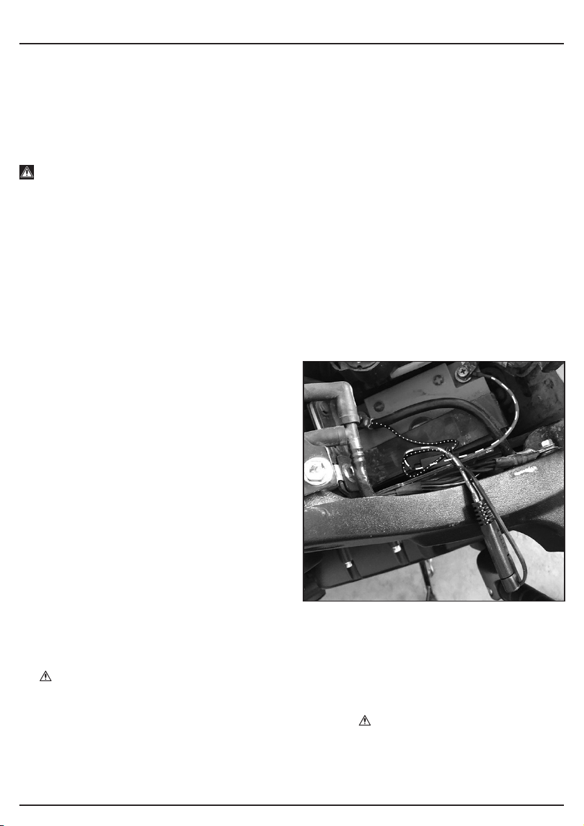
8. PREPARING THE BATTERY CHARGER
– 12 –
8.1 BEFORE CHARGING YOUR
BATTERY – FIGS. 1 – 2
We recommend that the battery is disconnected
from the vehicle, this will avoid any possible
damage to the alternator.
Loss of codes for audio and security etc, can be
prevented by connecting a Draper Memory
Saver – Stock No. 22277 12V socket type (Fig.1),
or Stock No. 22231 EOBD 16pin diagnostic
socket type (Fig.2) before disconnecting the
battery. Check that the voltage of the battery
matches that of the charger. 1FIG.
2FIG.
9.1 APPLICATION
The charger is designed for charging non maintenance-free or maintenance-free 12V lead acid
batteries (wet / Ca/Ca / EFB batteries) and for lead gel and AGM batteries which are used in
motor vehicles.
9.2 CONNECTION
Before you connect the equipment to the power supply make sure that the data on the
specifications label are identical to the supply voltage.
Warning! Do not charge any frozen batteries.
Please also refer to the instructions in the owner’s manuals for the car, radio, navigation
system, etc.
Notes on automatic charging (programs 12V STD, 12V AGM/C, 12V GEL, 12V LFP)
The charger is a microprocessor controlled automatic charger, i.e. it is suitable in particular for
charging maintenance-free batteries and for the long-term charging and maintenance-charging
of batteries which are not in constant use, e.g. for classic cars, recreational vehicles, lawn
tractors and the like. The integrated microprocessor enables charging in several steps. The
final charging step, maintenance charging, maintains the battery capacity at 95–100% and
therefore keeps the battery fully charged at all times. The charging operation does not need to
be monitored. However, do not leave the battery unattended if you charge it over an extended
period of time, so that you can disconnect it from the mains power supply in the event of a
fault in the charger.
9.3 PERMANENT INSTALLATION
OF “O”RINGS TO BATTERY – FIG. 3
The permanently installed “O” rings M8 allow
the battery to be connected to charger via
connector without obtaining access to battery.
(chiefly for motorbikes, classic cars, jetski’s etc
where access to battery is difficult).
9.4 SETTING THE CHARGING PROGRAMS
• If the voltage of the battery is less than 3.5V or more than 15V, the battery is either not
suitable for charging or it is faulty. The message “BAt” will appear in the LCD display. The
symbol will flash. It is also possible that other battery errors or faults can mean that the
battery cannot be charged.
• If there is a short-circuit between the charging terminals while the SUPPLY function is on,
the message “Lo V” will appear in the LCD display. The symbol will flash.
• When the charger is disconnected from the socket outlet, the last charging program to
have been set will be saved (apart from 6V STD and SUPPLY) and will be the default
program the next time the charger is used.
– 13 –
9. OPERATION
3FIG.

9. OPERATION
9.5 STANDARD CHARGING PROGRAMS
12V STD (6):Charging program for lead acid batteries (wet, Ca/Ca, EFB batteries) and gel
batteries. When the charger is used for the first time, 12V STD will appear in the display.
12V AGM/C (7):Charging program for AGM batteries and cold weather conditions
(ambient temperature of -20°C to +5°C) for normal lead acid batteries (wet / Ca/Ca batteries)
12V GEL: (8): Charging program for GEL batteries.
12V LFP: (9): Charging program for “Lithium iron phosphate” or LFP batteries.
9.6 SPECIAL CHARGING PROGRAMS
6V STD: (11):Charging program for 6V batteries
9.7 ADDITIONAL FUNCTION
SUPPLY (13):For supplying 12V D.C. voltage, e.g. when changing a battery or for
operating 12V D.C. consumers.
Warning! Protection against swapped poles will not be available. If the poles are
swapped there is a risk of damaging the charger and the battery/on-board vehicle power
supply or a connected consumer. It is imperative that you make sure the polarity is correct
when you connect up. Observe the maximum power consumption of the consumer.
Note:
• The direct voltage which is provided (shown in the display) is load-dependent and without
load it is approx. 14.5V.
• This function can be used for consumers which are operated from a vehicle’s cigarette lighter.
• Refer to and observe the operating manual for your 12V consumer.
9.8 CHARGING THE BATTERY
• Release or remove the battery stoppers (if fitted) from the battery.
• Check the acid level in the battery. If necessary, top up the battery with distilled water (if
possible).
Important! Battery acid is aggressive. Rinse off any acid splashes thoroughly with lots of
water and seek medical advice if necessary.
• Connect the battery clamps.
With a battery removed from vehicle:
a. Connect the RED positive charger lead to the positive (+) terminal on your battery.
b. Connect the BLACK negative charger lead to the negative (–) terminal on your battery
– 14 –
Normal
Press “Mode” to switch
between functions.
12V STD 12V AGM/C 12V GEL 12 LFP
Press “Mode” button for 5 seconds
to switch between Normal &
Additional functions
Additional functions
Press “Mode” to switch between functions.
6V STD SUPPLY

9. OPERATION
With a battery connected to vehicle:
Note: All loads in the vehicle must be switched off during charging.
a. Connect the RED positive charger lead to the positive (+) terminal on your battery.
b. Connect the BLACK negative charger lead to your vehicles ground connection on
either the engine or chassis, away from any fuel lines or the battery vents.
If the clamps are INCORRECTLY connected with regard to polarity, the LCD screen will
display the following (the + and - inside the battery icon, the fault icon and “Err”), and a
warning will sound until the clamps are disconnected. Unplug the charger, then remove the
clamps, reconnect the clamps properly.
Warning! Under normal circumstances the negative battery pole is connected to the bodywork
and you proceed as described above. In exceptional cases (refer to the manufacturers manual)
it is be possible that the positive battery pole is connected to the bodywork (positive earthing).
In this case connect the black charger cable to the negative pole on the battery. Then connect
the red charger cable to the bodywork at a point away from the battery and the petrol pipe.
• After the battery has been connected to the charger, you can connect the charger to a
socket. You can now change the charging settings.
• Important! Charging may create dangerous explosive gas and therefore you should
avoid spark formation and naked flames whilst the battery is charging. There is a risk of
explosion! It is essential that you ventilate the rooms well.
• When “FUL” appears in the LCD display, charging has been completed. The charger holds
the battery at 95% – 100% available battery capacity using pulsed charging. If the charger
shows this after just a few minutes, this indicates that the battery capacity is low. The
battery needs replacing.
9.9 FAULT INDICATOR
The fault indicator will flash (light up) in the following cases:
• If the voltage of the battery is less than 3.5 V or more than 15 V. The battery is either
unsuitable for charging or is defective. It is also possible that other battery errors or faults
can mean that the battery cannot be charged.
• If the terminal clamps are connected to the battery terminals with the wrong polarity. The
protection against swapped poles ensures that the battery and charger do not get damaged.
Remove the charger from the battery and start the charging process from the beginning again.
Caution! Protection against swapped poles is not available when the SUPPLY program is used.
• If there is a short-circuit between the two terminal clamps (the metal parts of the clamps
come into contact with each other). The protection against short-circuits ensures that the
battery and charger do not get damaged.
9.10 FINISHING CHARGING THE BATTERY
• Pull the plug out of the socket.
• Disconnect the black charging cable from the bodywork.
• Then release the red charging cable from the positive pole on the battery.
• Important! In case of positive earthing, first disconnect the red charging cable from the
bodywork and then the black charging cable from the battery.
• Screw or push the battery stoppers back into position (if there are any).
Important! If the mains plug is pulled out but the charger cables are still connected to the
battery, the charger will draw off a small amount of electricity from the battery. We therefore
recommend that you always completely remove the charger from the battery when not in use.
– 15 –
Normal
Press “Mode” to switch
between functions.
12V STD 12V AGM/C 12V GEL 12 LFP

9. OPERATION
– 16 –
STEP 0 Battery activated
After the selection of the charging mode,
the charger checks the status of the battery.
If the Voltage lower than 5V, will use trickle
charging to activate the battery.
STEP 1 Battery Devulcanization
After the selection of the charging mode,
the charger checks the status of the battery.
For batteries with vulcanization on the plate,
repeated charging with small current pulses
eliminates vulcanization, which increases the
battery capacity.
STEP 2 Battery Repair
After the selection of the charging mode, the
charger checks the status of the battery. For
old batteries or batteries that have not been
used for a long time, it will charge with pulse
current to expand the battery capacity again.
STEP 3 Pulse current charge
Save the battery with impulse charging
prepare for Bulk charging.
STEP 4 Constant current charging
Charging with maximum current until
approximately 80% battery capacity.
STEP 5 Constant voltage charging
Charging with steady charging voltage to
maximize up to 100% battery capacity.
STEP 6 Floating Charge
Charge optimization / Charge with small
Constant current charging
STEP 7 Flat Charge
Charge optimization / Charge with smaller
Constant current charging to maximize the
battery charge, try to reach a fully charged
state.
STEP 8 Analysis Bat tery
Stop 1 minutes, Analysis the charging
voltage, to determine whether is full.
STEP 9 Compensation Charge
Battery capacity will be kept at 95-100%
and the battery voltage will be supervised. If
necessary, the charger will give an impulse to
the battery to keep it completely recharged.
9.11 10 STEPS OF CHARGING 53489
Battery voltage
Charging Current
3A
1A
2A
4A
5A
STEPS STEP 0
Battery Activated
STEP 1
Devulcanization
STEP 2
Repair
STEP 3
Pulse current charge
STEP 4
CC
STEP 5
CV
STEP 6
Floating Charge
STEP 7
Flat Charge
STEP 8
Analysis Battery
STEP 9
Compensation Charge
MODE
12V STD
V <3V 5.2V 7.5V 10.5V 12.6V 13.6V 13.8V 14.5V 14.5V <13.2V
I Detection 0.5A 1.5A 1Hz 1.5A 1Hz 4A 3.6A-2.6A 2A 1.5A Detection 1.5A 1Hz
12V AGM/C
V <3V 5.2V 7.5V 10.5V 12.6V 13.6V 13.8V 14.8V 14.8V <13.2V
I Detection 0.5A 1.5A 1Hz 1.5A 1Hz 4A 3.6A-2.6A 2A 1.5A Detection 1.5A 1Hz
12V GEL
V <3V 5.2V 7.5V 10.5V 12.6V 13.6V 13.8V 14.3V 14.3V <13.2V
I Detection 0.5A 1.5A 1Hz 1.5A 1Hz 4A 3.6A-2.6A 2A 1.5A Detection 1.5A 1Hz
12V LFP
V <3V 5.2V 7.5V 10.5V 12.6V 13.6V 13.8V 14.6V 14.6V <13.2V
I Detection 2A 2A 2A 4A 3A 3A 3A-1A Detection 2A 1Hz
6V STD
V <3V 5.2V 5.5V 5.8V 6.3V 6.7V 7V 7.2V 7.2V <6.6V
I Detection 0.5A 1A 1Hz 2A 1Hz 2A 2A 2A 2A Detection 2A 1Hz
SUPPLY
V 14V
I 3A

9. OPERATION
– 17 –
STEP 0 Battery activated
After the selection of the charging mode,
the charger checks the status of the battery.
If the Voltage lower than 5V, will use trickle
charging to activate the battery.
STEP 1 Battery Devulcanization
After the selection of the charging mode,
the charger checks the status of the battery.
For batteries with vulcanization on the plate,
repeated charging with small current pulses
eliminates vulcanization, which increases the
battery capacity.
STEP 2 Battery Repair
After the selection of the charging mode, the
charger checks the status of the battery. For
old batteries or batteries that have not been
used for a long time, it will charge with pulse
current to expand the battery capacity again.
STEP 3 Pulse current charge
Save the battery with impulse charging
prepare for Bulk charging.
STEP 4 Constant current charging
Charging with maximum current until
approximately 80% battery capacity.
STEP 5 Constant voltage charging
Charging with steady charging voltage to
maximize up to 100% battery capacity.
STEP 6 Floating Charge
Charge optimization / Charge with small
Constant current charging
STEP 7 Flat Charge
Charge optimization / Charge with smaller
Constant current charging to maximize the
battery charge, try to reach a fully charged
state.
STEP 8 Analysis Battery
Stop 1 minutes, Analysis the charging
voltage, to determine whether is full.
STEP 9 Compensation Charge
Battery capacity will be kept at 95-100%
and the battery voltage will be supervised. If
necessary, the charger will give an impulse to
the battery to keep it completely recharged.
9.12 10 STEPS OF CHARGING 53490
Battery voltage
Charging Current
6A
2A
4A
8A
10A
STEPS STEP 0
Battery Activated
STEP 1
Devulcanization
STEP 2
Repair
STEP 3
Pulse current charge
STEP 4
CC
STEP 5
CV
STEP 6
Floating Charge
STEP 7
Flat Charge
STEP 8
Analysis Battery
STEP 9
Compensation Charge
MODE
12V STD
V <3V 5.2V 7.5V 10.5V 12.6V 13.6V 13.8V 14.5V 14.5V <13.2V
I Detection 0.5A 1.5A 1Hz 1.5A 1Hz 6A 5.4A-3.4A 2A 1.5A Detection 1.5A 1Hz
12V AGM/C
V <3V 5.2V 7.5V 10.5V 12.6V 13.6V 13.8V 14.8V 14.8V <13.2V
I Detection 0.5A 1.5A 1Hz 1.5A 1Hz 6A 5.4A-3.4A 2A 1.5A Detection 1.5A 1Hz
12V GEL
V <3V 5.2V 7.5V 10.5V 12.6V 13.6V 13.8V 14.3V 14.3V <13.2V
I Detection 0.5A 1.5A 1Hz 1.5A 1Hz 6A 5.4A-3.4A 2A 1.5A Detection 1.5A 1Hz
12V LFP
V <3V 5.2V 7.5V 10.5V 12.6V 13.6V 13.8V 14.6V 14.6V <13.2V
I Detection 2A 2A 2A 6A 5A 5A 5A-1A Detection 2A 1Hz
6V STD
V <3V 5.2V 5.5V 5.8V 6.3V 6.7V 7V 7.2V 7.2V <6.6V
I Detection 0.5A 1A 1Hz 2A 1Hz 2A 2A 2A 2A Detection 2A 1Hz
SUPPLY
V 14V
I 5A

9. OPERATION
– 18 –
STEP 0 Battery activated
After the selection of the charging mode, the
charging checks the status of the battery.
If the Voltage lower than 5V, will use trickle
charging to activate the battery.
STEP 1 Battery Devulcanization
After the selection of the charging mode,
the charger checks the status of the battery.
For batteries with vulcanization on the plate,
repeated charging with small current pulses
eliminates vulcanization, which increases the
battery capacity.
STEP 2 Battery Repair
After the selection of the charging mode, the
charger checks the status of the battery. For
old batteries or batteries that have not been
used for a long time, it will charge with pulse
current to expand the battery capacity again.
STEP 3 Pulse current charge
Save the battery with impulse charging
prepare for Bulk charging.
STEP 4 Constant current charging
Charging with maximum current until
approximately 80% battery capacity.
STEP 5 Constant voltage charging
Charging with steady charging voltage to
maximize up to 100% battery capacity.
STEP 6 Floating Charge
Charge optimization / Charge with small
Constant current charging
STEP 7 Flat Charge
Charge optimization / Charge with smaller
Constant current charging to maximize the
battery charge, try to reach a fully charged
state.
STEP 8 Analysis Battery
Stop 1 minutes, Analysis the charging
voltage, to determine whether is full.
STEP 9 Compensation Charge
Battery capacity will be kept at 95-100%
and the battery voltage will be supervised. If
necessary, the charger will give an impulse to
the battery to keep it completely recharged.
Battery voltage
Charging Current
6A
2A
4A
8A
10A
9.13 10 STEPS OF CHARGING 53491
STEPS STEP 0
Battery Activated
STEP 1
Devulcanization
STEP 2
Repair
STEP 3
Pulse current charge
STEP 4
CC
STEP 5
CV
STEP 6
Floating Charge
STEP 7
Flat Charge
STEP 8
Analysis Battery
STEP 9
Compensation Charge
MODE
12V STD
V <3V 5.2V 7.5V 10.5V 12.6V 13.6V 13.8V 14.5V 14.5V <13.2V
I Detection 0.5A 1.5A 1Hz 1.5A 1Hz 10A 9A-6.5A 2A 1.5A Detection 1.5A 1Hz
12V AGM/C
V <3V 5.2V 7.5V 10.5V 12.6V 13.6V 13.8V 14.8V 14.8V <13.2V
I Detection 0.5A 1.5A 1Hz 1.5A 1Hz 10A 9A-6.5A 2A 1.5A Detection 1.5A 1Hz
12V GEL
V <3V 5.2V 7.5V 10.5V 12.6V 13.6V 13.8V 14.3V 14.3V <13.2V
I Detection 0.5A 1.5A 1Hz 1.5A 1Hz 10A 9A-6.5A 2A 1.5A Detection 1.5A 1Hz
12V LFP
V <3V 5.2V 7.5V 10.5V 12.6V 13.6V 13.8V 14.6V 14.6V <13.2V
I Detection 2A 2A 2A 10A 8A 8A 8A-1A Detection 2A 1Hz
6V STD
V <3V 5.2V 5.5V 5.8V 6.3V 6.7V 7V 7.2V 7.2V <6.6V
I Detection 0.5A 1A 1Hz 2A 1Hz 2A 2A 2A 2A Detection 2A 1Hz
SUPPLY
V 14V
I 10A

– 19 –
10. MAINTENANCE AND TROUBLESHOOTING
10.1 MAINTENANCE
Regular inspection and cleaning reduces the necessity for maintenance operations and will
keep your tool in good working condition.
The motor must be correctly ventilated during tool operation. Avoid blocking the air inlets and
vacuum the ventilation slots regularly.
10.2 TROUBLESHOOTING GUIDE
Problem Possible Cause Remedy
Equipment does not
charge up
1. Charger clamps
connected incorrectly.
1. Connect the red clamp
to the positive pole and
the back clamp to the
bodywork.
2. Contact between the
charger clamps
2. Prevent contact.
3. Battery defective 3. Have the battery checked
by an expert and replace
it if necessary.
Note: If the battery to be charged has fallen below 2 volts, the battery cannot be recharged
with this charger.

11. EXPLANATION OF SYMBOLS
– 20 –
11.1 EXPLANATION OF SYMBOLS
Read the instruction manual.
Do not abandon into
the environment.
Keep out of the reach
of children.
Warning!
Do not incinerate or throw
onto fire.
For indoor use only.
Do not expose to rain.
Short-circuit-proof safety
isolating transformer.
130° Fuse protective device.
Polarity indication.
Rated voltage.
Class II construction
(Double insulated).
WEEE –
Waste Electrical & Electronic Equipment.
Do not dispose of Waste Electrical & Electronic
Equipment in with domestic rubbish.
This manual suits for next models
2
Table of contents
Other Draper Batteries Charger manuals

Draper
Draper BCS230B Firmware update

Draper
Draper BCD12 User manual

Draper
Draper BCD11 User manual

Draper
Draper BCHF10 User manual

Draper
Draper BCSD300T User manual

Draper
Draper 03295 Expert User manual

Draper
Draper BCD18A User manual

Draper
Draper C18UB User manual

Draper
Draper IBC1 User manual

Draper
Draper BCD5 User manual

Draper
Draper BCSD130 User manual

Draper
Draper MTC100 User manual

Draper
Draper BC14 Firmware update

Draper
Draper 70549 User manual

Draper
Draper 66800 User manual

Draper
Draper BC15ACO User manual

Draper
Draper BC30A User manual

Draper
Draper BCI5 User manual

Draper
Draper 33861 User manual

Draper
Draper 70548 User manual


