5
OBS!!! MAX 10 SEKUNDER MELLAN TVÅ KOMMANDON FÖR ATT DET SKA BLI BEKRÄFTAT.
!
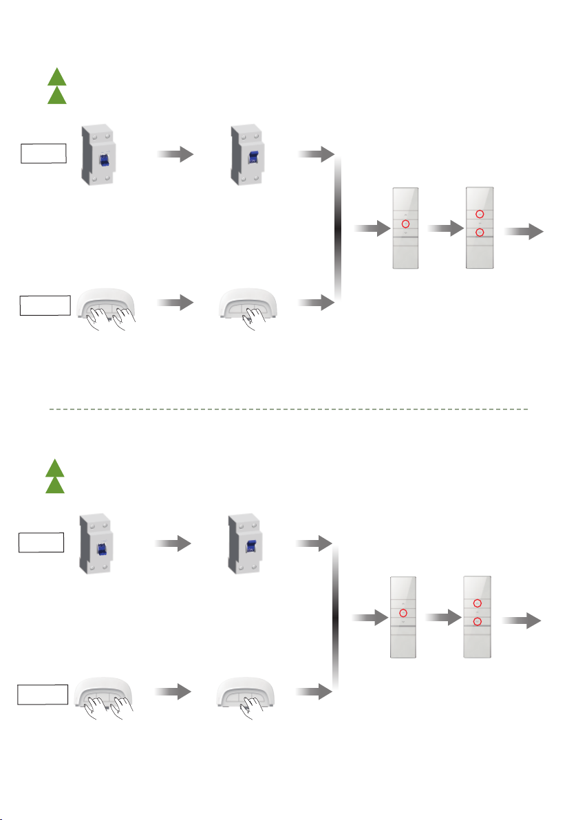
PROGRAMMERING
LÄGGA TILL FJÄRRKONTROLL OCH VÄLJA ROTOATIONSRIKTNING
PROGRAMMING
ADD REMOTE CONTROL AND CHOOSE DIRECTION OF ROTATION
Blue LED
flashes×1
Blue LED
flashes×1
Blue LED
flashes×2
Power on
P2×1 P2×1 P2×1
OK
New emitter is paired to the motor
DD1620A External Switch Signal And Serial Port 485 Control
Note: ①During the setting status, every operation should be less then 10S, or else, it will exit the setting and back to original
status; ②Repeat same procedure will delete additional emitter.
Method one
Method two
Pairing / Delete Additional Emitter
Note: ①During the setting status, every operation should be less then 10S, or else, it will exit the setting and back to original
status; ②as existing emitter, as new emitter to pair or delete;
③
Repeat same procedure will delete additional emitter.
A. Infrared receiving function: ①infrared emission port registry with the middle area of healing, can control motor; ②The external infrared interface can be
connected with 1 Infrared joints, which can be controlled by the infrared emission port. ③The infrared control distance is within 10 meters.
B. External trigger function (projection screen function): ①The external trigger interface can be connected to the 12V signal. ②When the 12V signal is connected,
trigger motor running downward. ③When the 12V signal is disconnected, Trigger motor running upward.
C. External serial port: DD1620 is 232 serial port; DD1620A is 485 serial port.
Wiring
DD1620 External Switch Signal And Serial Port 232 Control
DOWN
STOP
UP
External switch
and serial port
External
infrared interface
External
trigger interface
Blue line = power neutral line
Brown line = power live line
Green/yellow line = power earth wire
Power
connection
Signal
line
Motor
interface
Power
interface
Signal indicator light (blue)
Infrared receiving head
Control indicator light (red)
Brown line = motor forward line
Black line = motor reversing line
Blue line = common line
Yellow/green line =motor earth wire
Motor
connection
UP
STOP
DOWN
External
trigger interface
External
infrared interface
External
switch and
serial port
Power neutral line
Power live line
Power grounding
wire
Motor reversing line
Motor common line
Motor motor
forward line
Motor grounding wire
External pulse switch:
①The green line (UP) and the black line (COM) touch to
control motor running upward.
②The red line (STOP) and the black line (COM) touch to
control the motor stop.
③The yellow line (DOWN) and the black line (COM) touch
to control motor running downward.
Serial port control needs to be connected to the computer for operation
The white line (RX) and the blue line (TX) are connected to the RS232
serial port (DD1620)
①When the white line (RX) receives 55 FE FE 03 01 B9 24,
can controlled the motor running upward.
②When the white line (RX) receives 55 FE FE 03 03 38 E5,
can controlled the motor stop;
③When the white line (RX) receives 55 FE FE 03 02 F9 25,
can controlled the motor running downward.
①Reserve
②White line(RX)→Connect
the TX side of the RS232
③Black line(COM)→Connect
the GND side of the RS232
④Red line(STOP)
⑤Green line(UP)
⑥Yellow line(DOWN)
⑦Blue line(TX)→Connect
the RX side of the RS232
⑧Reserve
①Reserve
②White line(A)→Connect
the A side of the RS485
③Black line(COM)→Connect
the GND side of the RS485
④Red line(STOP)
⑤Green line(UP)
⑥Yellow line(DOWN)
⑦Blue line(B)→Connect
the B side of the RS485
⑧Reserve
External pulse switch:
①The green line (UP) and the black line (COM) touch to
control motor running upward.
②The red line (STOP) and the black line (COM) touch to
control the motor stop.
③The yellow line (DOWN) and the black line (COM) touch
to control motor running downward.
Serial port control needs to be connected to the computer for operation
The white line (A) and the blue line (B) are connected to the RS485 serial
port (DD1620A)
①When the white line (A) receives 55 FE FE 03 01 B9 24,
can controlled the motor running upward.
②When the white line (A) receives 55 FE FE 03 03 38 E5,
can controlled the motor stop;
③When the white line (A) receives 55 FE FE 03 02 F9 25,
can controlled the motor running downward.
AC 220V/50Hz
AC 220V/50Hz
Blue LED
flashes×1
Power onPower off
OFF
Blue LED
flashes×2
STOP×2s
OK
Emitter is paired to the motor
STOP×2s
Release button
after blue LED
flashes
(UP+DOWN)
×2S
Håll 3 sek:
UPP + NER
BLÅ LED
blinkar
Håll 3 sek:
STOPP
Släpp när BLÅ
LED blinkat
1 gång.
RÖD LED lyser
nu konstant
Bryt ström Anslut ström
Vänta 10 sek
ALT. 1:
ALT. 2:
BLÅ LED
blinkar 1 gång
Håll 3 sek:
STOPP
Blue LED
flashes×1
Blue LED
flashes×1
Blue LED
flashes×2
Power on
P2×1 P2×1 P2×1
OK
New emitter is paired to the motor
DD1620A External Switch Signal And Serial Port 485 Control
Note: ①During the setting status, every operation should be less then 10S, or else, it will exit the setting and back to original
status; ②Repeat same procedure will delete additional emitter.
Method one
Method two
Pairing / Delete Additional Emitter
Note: ①During the setting status, every operation should be less then 10S, or else, it will exit the setting and back to original
status; ②as existing emitter, as new emitter to pair or delete;
③
Repeat same procedure will delete additional emitter.
A. Infrared receiving function: ①infrared emission port registry with the middle area of healing, can control motor; ②The external infrared interface can be
connected with 1 Infrared joints, which can be controlled by the infrared emission port. ③The infrared control distance is within 10 meters.
B. External trigger function (projection screen function): ①The external trigger interface can be connected to the 12V signal. ②When the 12V signal is connected,
trigger motor running downward. ③When the 12V signal is disconnected, Trigger motor running upward.
C. External serial port: DD1620 is 232 serial port; DD1620A is 485 serial port.
Wiring
DD1620 External Switch Signal And Serial Port 232 Control
DOWN
STOP
UP
External switch
and serial port
External
infrared interface
External
trigger interface
Blue line = power neutral line
Brown line = power live line
Green/yellow line = power earth wire
Power
connection
Signal
line
Motor
interface
Power
interface
Signal indicator light (blue)
Infrared receiving head
Control indicator light (red)
Brown line = motor forward line
Black line = motor reversing line
Blue line = common line
Yellow/green line =motor earth wire
Motor
connection
UP
STOP
DOWN
External
trigger interface
External
infrared interface
External
switch and
serial port
Power neutral line
Power live line
Power grounding
wire
Motor reversing line
Motor common line
Motor motor
forward line
Motor grounding wire
External pulse switch:
①The green line (UP) and the black line (COM) touch to
control motor running upward.
②The red line (STOP) and the black line (COM) touch to
control the motor stop.
③The yellow line (DOWN) and the black line (COM) touch
to control motor running downward.
Serial port control needs to be connected to the computer for operation
The white line (RX) and the blue line (TX) are connected to the RS232
serial port (DD1620)
①When the white line (RX) receives 55 FE FE 03 01 B9 24,
can controlled the motor running upward.
②When the white line (RX) receives 55 FE FE 03 03 38 E5,
can controlled the motor stop;
③When the white line (RX) receives 55 FE FE 03 02 F9 25,
can controlled the motor running downward.
①Reserve
②White line(RX)→Connect
the TX side of the RS232
③Black line(COM)→Connect
the GND side of the RS232
④Red line(STOP)
⑤Green line(UP)
⑥Yellow line(DOWN)
⑦Blue line(TX)→Connect
the RX side of the RS232
⑧Reserve
①Reserve
②White line(A)→Connect
the A side of the RS485
③Black line(COM)→Connect
the GND side of the RS485
④Red line(STOP)
⑤Green line(UP)
⑥Yellow line(DOWN)
⑦Blue line(B)→Connect
the B side of the RS485
⑧Reserve
External pulse switch:
①The green line (UP) and the black line (COM) touch to
control motor running upward.
②The red line (STOP) and the black line (COM) touch to
control the motor stop.
③The yellow line (DOWN) and the black line (COM) touch
to control motor running downward.
Serial port control needs to be connected to the computer for operation
The white line (A) and the blue line (B) are connected to the RS485 serial
port (DD1620A)
①When the white line (A) receives 55 FE FE 03 01 B9 24,
can controlled the motor running upward.
②When the white line (A) receives 55 FE FE 03 03 38 E5,
can controlled the motor stop;
③When the white line (A) receives 55 FE FE 03 02 F9 25,
can controlled the motor running downward.
AC 220V/50Hz
AC 220V/50Hz
Blue LED
flashes×1
Power onPower off
OFF
Blue LED
flashes×2
STOP×2s
OK
Emitter is paired to the motor
STOP×2s
Release button
after blue LED
flashes
(UP+DOWN)
×2S
DD1620(A)
Projection screen
L1
Power on
P2×1 STOP×1 P2×1
OK
All emitters are deleted
Note: ①During the setting status, every operation should be less then 10S, or else, it will exit the setting and back to original
status.
Note: after the controller enters radio lock status, press any button to exit this mode.
Delete All Emitters
Controller Button Operation
Switch Rotating Direction
Blue LED
flashes×1
Blue LED
flashes×1
Blue LED
flashes×
1
Blue LED
flashes×2
Blue LED
flashes×1
Blue LED
flashes×1
Blue LED
flashes×2
Power on
P2×1
Power on
P2×1 STOP×2s
OK
OK
Within 30S after
adding the Emitter
successfully
Method three
Note: ①During the setting status, every operation should be less then 10S, or else, it will exit the setting and back to original
status; ②Press UP and motor runs downwards, try below to switch direction.
(UP+DOWN)×2S
New emitter is paired to the motor
The direction has been switched successfully
DD1802H
15-channel
LCD Emitter
DD1600H
Single-channel
Emitter
DD1800H
Single-channel
Emitter
DD1602H
15-channel
LCD Emitter
DD1620(A) controller
DD1620(A)
Controller Instruction
Version: A/01
Note: ①The maximum run time is 4 minutes; ②When emitter is under group control, match code will be invalid.
DD1620 is a RS232 protocol, and DD1620A is a RS485 protocol
Infrared reception function(Equipped with DC95 infrared emitter)
Input voltage: AC 220V/50Hz
Rated power: 300W
Working temperature: -10℃~ +65℃
One DD1620(A) controller can store maximum 10 emitter channels.
If there are already 10 channels, it will take turns to cover the last channel.
DD1620(A)
Projection screen
L2
0.3m 0.2m
0.3m
1.5m
Matchable Emitter
DM35S
DM45S
DD1600H
Single-channel
Emitter
DD1600H
Back
Setting
button
(P2)
Product Features
Matchable Motor &
Button Instructions
The Best Installation
Distance
UP
STOP
DOWN
UP
STOP
DOWN
DC95
infrared emitter
Note: Effective transmitting distancemay have deviation due to actual environment.
Control Range
L1 open L2 partition Reception frequency
AC 220V/50Hz 200m 35m 433.92MHz±100KHz
The shortest distance between controller
and ground ≥1.5m
The shortest distance between controller
and roof ≥0.3m
The shortest distance between controller
and receive ≥0.2m
Note: ①During the setting status, every operation should be less then 10S, or else, it will exit the setting and back to original
status; ②as existing emitter, as new emitter to pair.
Release button
after blue LED
flashes The controller
enters the
setting state.
(UP+DOWN)×2S
Release button
after blue LED
flashes once
The controller enters the
pairing / delete emitter state.
STOP×2s
Release button
after blue LED
flashes 2 times
The controller enters
radio lock state.
Release button
after blue LED
flashes 3 times
The direction has been
switched successfully.
Release button
after blue LED
flashes 4 times
The motor has been reset to
factory mode.
STOP×6s
STOP×10s
STOP×14s
BLÅ LED
blinkar
2 gånger
Fel rotations-
riktning?
Håll 3 sek:
UPP+NER.
RÖD LED
släcks
1 sek
Blue LED
flashes×1
Blue LED
flashes×1
Blue LED
flashes×2
Power on
P2×1 P2×1 P2×1
OK
New emitter is paired to the motor
DD1620A External Switch Signal And Serial Port 485 Control
Note: ①During the setting status, every operation should be less then 10S, or else, it will exit the setting and back to original
status; ②Repeat same procedure will delete additional emitter.
Method one
Method two
Pairing / Delete Additional Emitter
Note: ①During the setting status, every operation should be less then 10S, or else, it will exit the setting and back to original
status; ②as existing emitter, as new emitter to pair or delete;
③
Repeat same procedure will delete additional emitter.
A. Infrared receiving function: ①infrared emission port registry with the middle area of healing, can control motor; ②The external infrared interface can be
connected with 1 Infrared joints, which can be controlled by the infrared emission port. ③The infrared control distance is within 10 meters.
B. External trigger function (projection screen function): ①The external trigger interface can be connected to the 12V signal. ②When the 12V signal is connected,
trigger motor running downward. ③When the 12V signal is disconnected, Trigger motor running upward.
C. External serial port: DD1620 is 232 serial port; DD1620A is 485 serial port.
Wiring
DD1620 External Switch Signal And Serial Port 232 Control
DOWN
STOP
UP
External switch
and serial port
External
infrared interface
External
trigger interface
Blue line = power neutral line
Brown line = power live line
Green/yellow line = power earth wire
Power
connection
Signal
line
Motor
interface
Power
interface
Signal indicator light (blue)
Infrared receiving head
Control indicator light (red)
Brown line = motor forward line
Black line = motor reversing line
Blue line = common line
Yellow/green line =motor earth wire
Motor
connection
UP
STOP
DOWN
External
trigger interface
External
infrared interface
External
switch and
serial port
Power neutral line
Power live line
Power grounding
wire
Motor reversing line
Motor common line
Motor motor
forward line
Motor grounding wire
External pulse switch:
①The green line (UP) and the black line (COM) touch to
control motor running upward.
②The red line (STOP) and the black line (COM) touch to
control the motor stop.
③The yellow line (DOWN) and the black line (COM) touch
to control motor running downward.
Serial port control needs to be connected to the computer for operation
The white line (RX) and the blue line (TX) are connected to the RS232
serial port (DD1620)
①When the white line (RX) receives 55 FE FE 03 01 B9 24,
can controlled the motor running upward.
②When the white line (RX) receives 55 FE FE 03 03 38 E5,
can controlled the motor stop;
③When the white line (RX) receives 55 FE FE 03 02 F9 25,
can controlled the motor running downward.
①Reserve
②White line(RX)→Connect
the TX side of the RS232
③Black line(COM)→Connect
the GND side of the RS232
④Red line(STOP)
⑤Green line(UP)
⑥Yellow line(DOWN)
⑦Blue line(TX)→Connect
the RX side of the RS232
⑧Reserve
①Reserve
②White line(A)→Connect
the A side of the RS485
③Black line(COM)→Connect
the GND side of the RS485
④Red line(STOP)
⑤Green line(UP)
⑥Yellow line(DOWN)
⑦Blue line(B)→Connect
the B side of the RS485
⑧Reserve
External pulse switch:
①The green line (UP) and the black line (COM) touch to
control motor running upward.
②The red line (STOP) and the black line (COM) touch to
control the motor stop.
③The yellow line (DOWN) and the black line (COM) touch
to control motor running downward.
Serial port control needs to be connected to the computer for operation
The white line (A) and the blue line (B) are connected to the RS485 serial
port (DD1620A)
①When the white line (A) receives 55 FE FE 03 01 B9 24,
can controlled the motor running upward.
②When the white line (A) receives 55 FE FE 03 03 38 E5,
can controlled the motor stop;
③When the white line (A) receives 55 FE FE 03 02 F9 25,
can controlled the motor running downward.
AC 220V/50Hz
AC 220V/50Hz
Blue LED
flashes×1
Power onPower off
OFF
Blue LED
flashes×2
STOP×2s
OK
Emitter is paired to the motor
STOP×2s
Release button
after blue LED
flashes
(UP+DOWN)
×2S
Hold 3 sec:
UP+DOWN
BLUE LED
flashes
Hold 3 sec:
STOP
Release after
BLUE LED flas-
hes once.
RED LED
constant light
Power off Power on
Wait 10 sec.
ALT. 1:
ALT. 2:
BLUE LED
flashes once
Hold 3 sec:
STOP
Blue LED
flashes×1
Blue LED
flashes×1
Blue LED
flashes×2
Power on
P2×1 P2×1 P2×1
OK
New emitter is paired to the motor
DD1620A External Switch Signal And Serial Port 485 Control
Note: ①During the setting status, every operation should be less then 10S, or else, it will exit the setting and back to original
status; ②Repeat same procedure will delete additional emitter.
Method one
Method two
Pairing / Delete Additional Emitter
Note: ①During the setting status, every operation should be less then 10S, or else, it will exit the setting and back to original
status; ②as existing emitter, as new emitter to pair or delete;
③
Repeat same procedure will delete additional emitter.
A. Infrared receiving function: ①infrared emission port registry with the middle area of healing, can control motor; ②The external infrared interface can be
connected with 1 Infrared joints, which can be controlled by the infrared emission port. ③The infrared control distance is within 10 meters.
B. External trigger function (projection screen function): ①The external trigger interface can be connected to the 12V signal. ②When the 12V signal is connected,
trigger motor running downward. ③When the 12V signal is disconnected, Trigger motor running upward.
C. External serial port: DD1620 is 232 serial port; DD1620A is 485 serial port.
Wiring
DD1620 External Switch Signal And Serial Port 232 Control
DOWN
STOP
UP
External switch
and serial port
External
infrared interface
External
trigger interface
Blue line = power neutral line
Brown line = power live line
Green/yellow line = power earth wire
Power
connection
Signal
line
Motor
interface
Power
interface
Signal indicator light (blue)
Infrared receiving head
Control indicator light (red)
Brown line = motor forward line
Black line = motor reversing line
Blue line = common line
Yellow/green line =motor earth wire
Motor
connection
UP
STOP
DOWN
External
trigger interface
External
infrared interface
External
switch and
serial port
Power neutral line
Power live line
Power grounding
wire
Motor reversing line
Motor common line
Motor motor
forward line
Motor grounding wire
External pulse switch:
①The green line (UP) and the black line (COM) touch to
control motor running upward.
②The red line (STOP) and the black line (COM) touch to
control the motor stop.
③The yellow line (DOWN) and the black line (COM) touch
to control motor running downward.
Serial port control needs to be connected to the computer for operation
The white line (RX) and the blue line (TX) are connected to the RS232
serial port (DD1620)
①When the white line (RX) receives 55 FE FE 03 01 B9 24,
can controlled the motor running upward.
②When the white line (RX) receives 55 FE FE 03 03 38 E5,
can controlled the motor stop;
③When the white line (RX) receives 55 FE FE 03 02 F9 25,
can controlled the motor running downward.
①Reserve
②White line(RX)→Connect
the TX side of the RS232
③Black line(COM)→Connect
the GND side of the RS232
④Red line(STOP)
⑤Green line(UP)
⑥Yellow line(DOWN)
⑦Blue line(TX)→Connect
the RX side of the RS232
⑧Reserve
①Reserve
②White line(A)→Connect
the A side of the RS485
③Black line(COM)→Connect
the GND side of the RS485
④Red line(STOP)
⑤Green line(UP)
⑥Yellow line(DOWN)
⑦Blue line(B)→Connect
the B side of the RS485
⑧Reserve
External pulse switch:
①The green line (UP) and the black line (COM) touch to
control motor running upward.
②The red line (STOP) and the black line (COM) touch to
control the motor stop.
③The yellow line (DOWN) and the black line (COM) touch
to control motor running downward.
Serial port control needs to be connected to the computer for operation
The white line (A) and the blue line (B) are connected to the RS485 serial
port (DD1620A)
①When the white line (A) receives 55 FE FE 03 01 B9 24,
can controlled the motor running upward.
②When the white line (A) receives 55 FE FE 03 03 38 E5,
can controlled the motor stop;
③When the white line (A) receives 55 FE FE 03 02 F9 25,
can controlled the motor running downward.
AC 220V/50Hz
AC 220V/50Hz
Blue LED
flashes×1
Power onPower off
OFF
Blue LED
flashes×2
STOP×2s
OK
Emitter is paired to the motor
STOP×2s
Release button
after blue LED
flashes
(UP+DOWN)
×2S
DD1620(A)
Projection screen
L1
Power on
P2×1 STOP×1 P2×1
OK
All emitters are deleted
Note: ①During the setting status, every operation should be less then 10S, or else, it will exit the setting and back to original
status.
Note: after the controller enters radio lock status, press any button to exit this mode.
Delete All Emitters
Controller Button Operation
Switch Rotating Direction
Blue LED
flashes×1
Blue LED
flashes×1
Blue LED
flashes×1
Blue LED
flashes×2
Blue LED
flashes×1
Blue LED
flashes×1
Blue LED
flashes×2
Power on
P2×1
Power on
P2×1 STOP×2s
OK
OK
Within 30S after
adding the Emitter
successfully
Method three
Note: ①During the setting status, every operation should be less then 10S, or else, it will exit the setting and back to original
status; ②Press UP and motor runs downwards, try below to switch direction.
(UP+DOWN)×2S
New emitter is paired to the motor
The direction has been switched successfully
DD1802H
15-channel
LCD Emitter
DD1600H
Single-channel
Emitter
DD1800H
Single-channel
Emitter
DD1602H
15-channel
LCD Emitter
DD1620(A) controller
DD1620(A)
Controller Instruction
Version: A/01
Note: ①The maximum run time is 4 minutes; ②When emitter is under group control, match code will be invalid.
DD1620 is a RS232 protocol, and DD1620A is a RS485 protocol
Infrared reception function(Equipped with DC95 infrared emitter)
Input voltage: AC 220V/50Hz
Rated power: 300W
Working temperature: -10℃~ +65℃
One DD1620(A) controller can store maximum 10 emitter channels.
If there are already 10 channels, it will take turns to cover the last channel.
DD1620(A)
Projection screen
L2
0.3m 0.2m
0.3m
1.5m
Matchable Emitter
DM35S
DM45S
DD1600H
Single-channel
Emitter
DD1600H
Back
Setting
button
(P2)
Product Features
Matchable Motor &
Button Instructions
The Best Installation
Distance
UP
STOP
DOWN
UP
STOP
DOWN
DC95
infrared emitter
Note: Effective transmitting distancemay have deviation due to actual environment.
Control Range
L1 open L2 partition Reception frequency
AC 220V/50Hz 200m 35m 433.92MHz±100KHz
The shortest distance between controller
and ground ≥1.5m
The shortest distance between controller
and roof ≥0.3m
The shortest distance between controller
and receive ≥0.2m
Note: ①During the setting status, every operation should be less then 10S, or else, it will exit the setting and back to original
status; ②as existing emitter, as new emitter to pair.
Release button
after blue LED
flashes The controller
enters the
setting state.
(UP+DOWN)×2S
Release button
after blue LED
flashes once
The controller enters the
pairing / delete emitter state.
STOP×2s
Release button
after blue LED
flashes 2 times
The controller enters
radio lock state.
Release button
after blue LED
flashes 3 times
The direction has been
switched successfully.
Release button
after blue LED
flashes 4 times
The motor has been reset to
factory mode.
STOP×6s
STOP×10s
STOP×14s
BLUE LED
flashes
twice
Wrong
direction of
rotation?
Hold 3 sek:
UP+DOWN
RED LED
gœs out
1 sec.
OBS!!! MAX 10 SECONDS BETWEEN TWO COMMANDS TO CONFIRM PROGRAMMING.
!
NOTERA: UPPREPA SAMMA PROCEDUR FÖR ATT TA BORT FJÄRRKONTROLL.
!
NOTE: REPEAT SAME PROCEDURE TO DELETE REMOTE CONTROL.
!