Source VERSA-WEDGE User manual

SOURCE VERSA GATE VALVES
API 6A LICENSE
LICENSE NO. 6A-0541 API 6D LICENSE
LICENSE NO. 6D-0477
Issued 210723
VERSA-WEDGETM GATE VALVES

SOURCE VERSA VALVES
Table of Content
VERSA VALVE FEATURES
Expanding Gate Valve(Non-Rising Stem) Brochure
Expanding Gate Valve(Rising Stem) Brochure
TECHNICAL INFORMATION
Valve Reference Dimensions and Weights
Recommended Flange Bolt Lengths and Ring Gasket
Gate Valve Trim Chart
OPERATING AND SERVICE MANUAL
Expanding Gate Valve(Non-rising Stem)
Expanding Gate Valve(Rising Stem)

DRILLING & PRODUCTION GEOTHERMAL WELLHEAD VALVE
API 6D LICENSE
LICENSE NO. 6D-0477
VERSA-WEDGETM GATE VALVE
SV-04 R00

PRODUCTS INTRODUCTION
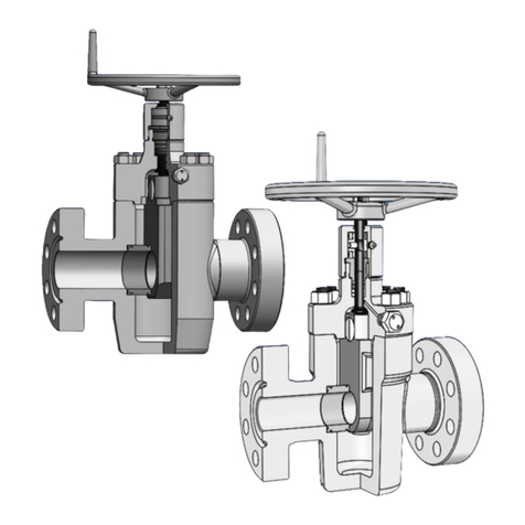
The GEOTHERMAL EXPANDING GATE VALVE is an unidirectional manual operated valve with
non-rising or rising stem and parallel expanding gate and segment design. The parallel expanding
gate design provides a tight mechanical seal which is normally unaffected by pressure fluctuations
or variations. The gate assembly uses an angular gate face which is collapsed during travel. When
closed, a stop causes any further downward travel to force the faces of the gate assembly outward
to effect a positive line flow seal. When opened, a stop causes any further upward travel to force
bottom faces to expand and seal against the seats to isolate flow from the valve body cavity.
The stem is sealed by reinforced graphite packing and injectable packing. In an emergency,
injecting injectable packing into packing box would affect a temporary seal while the valve is under
pressure.
The expanding valve is designed, manufactured and tested in accordance with API Spec. 6A unless
otherwise specified.
Steel reinforced
graphite stem
packing to provide
excellent resistance
to chemicals and
corrosive elements
Shrink Fit for Seat
and Body to create
a metal to metal
seal
Stellite hard-
faced gate and
seat
Upper and lower
roller thrust bearings
are isolated from
well fluid, minimizing
torque
FEATURES:
‒Nominal Size 2-1/16”, 3-1/8”
‒Work Pressure 2000-5000psi
‒Metal to Metal Seal (Gate-to-Seat & Seat-to-Body)
‒Steel Reinforced Graphite Packing and Injectable Packing
‒High Temperature up to 650˚F (Class Y)
‒Non-rising Stem with Handwheel Operation
‒Option of Cast or Forged Body
‒Expanding Wedge Gate and Seats Design
‒Flange Connection refer to requirement of API 6A

PRODUCT VIEW AND FUNCTION
THREE OPERATION STATUS:
Fully Opened:
The segment is stopped by
contacting with the bonnet
stop. The gate continuous
moving up to expand the
segment and gate against
both seats to form a
positive mechanical seal,
no matter with or without
line pressure
Stroking Position:
When stroking to open or
closed position, the gate
and segment is held by
spring with no forced
contact in between closure
member (gate and
segment) against the
seats which minimize
friction during stroking.
Fully Closed:
The segment going down is
stopped by contact with the
bottom body. The gate
continuous moving down to
expand the segment and
gate against both seats to
form a positive mechanical
seal, no matter with or
without line pressure.
Segment
Gate
Spring

GEOTHERMAL WELLHEAD VALVE
Source Manufacturing (Shanghai) Co., Ltd
988 Xiang Jing Road, Songjiang District
Shanghai 201613, P.R.China
Tel: 86 21 57775088
Fax: 86 21 57775068
Email: sales@source-mfg.com
Packing Set
Metal to Metal
Seal Seat to Gate
Inject Fitting
Shrink Fit
Seat to Body
Seat
Body
Bearing
Bolt & Nut
Gasket
Zerk Fitting
Stem
Handwheel
Gate Guide
Grease Fitting
Gate
Assembly
Bonnet
Packing Gland
Lock Nut
Sleeve

DRILLING & PRODUCTION GEOTHERMAL WELLHEAD VALVE
API 6D LICENSE
LICENSE NO. 6D-0477
VERSA-WEDGETM GATE VALVE
SV-05 R00

PRODUCTS INTRODUCTION
The GEOTHERMAL EXPANDING GATE VALVE is an unidirectional manual operated valve with
non-rising or rising stem and parallel expanding gate and segment design. The parallel expanding
gate design provides a tight mechanical seal which is normally unaffected by pressure fluctuations
or variations. The gate assembly uses an angular gate face which is collapsed during travel. When
closed, a stop causes any further downward travel to force the faces of the gate assembly outward
to effect a positive line flow seal. When opened, a stop causes any further upward travel to force
bottom faces to expand and seal against the seats to isolate flow from the valve body cavity.
The stem is sealed by reinforced graphite packing and injectable packing. In an emergency,
injecting injectable packing into packing box would affect a temporary seal while the valve is under
pressure.
The expanding valve is designed, manufactured and tested in accordance with API Spec. 6A unless
otherwise specified.
Steel reinforced
graphite stem
packing to provide
excellent resistance
to chemicals and
corrosive elements
Shrink Fit for Seat
and Body to create
a metal to metal
seal
Stellite hard-
faced gate and
seat
Upper and lower
roller thrust bearings
are isolated from
well fluid, minimizing
torque
FEATURES:
‒Nominal Size 2-1/16”, 3-1/8”
‒Work Pressure 2000-5000psi
‒Metal to Metal Seal (Gate-to-Seat & Seat-to-Body)
‒Steel Reinforced Graphite Packing and Injectable Packing
‒High Temperature up to 650˚F (Class Y)
‒Rising Stem with Handwheel Operation
‒Option of Cast or Forged Body
‒Expanding Wedge Gate and Seats Design
‒Flange Connection refer to requirement of API 6A

PRODUCT VIEW AND FUNCTION
THREE OPERATION STATUS:
Fully Opened:
The segment is stopped by
contacting with the bonnet
stop. The gate continuous
moving up to expand the
segment and gate against
both seats to form a
positive mechanical seal,
no matter with or without
line pressure
Stroking Position:
When stroking to open or
closed position, the gate
and segment is held by
spring with no forced
contact in between closure
member (gate and
segment) against the
seats which minimize
friction during stroking.
Fully Closed:
The segment going down is
stopped by contact with the
bottom body. The gate
continuous moving down to
expand the segment and
gate against both seats to
form a positive mechanical
seal, no matter with or
without line pressure.
Segment
Gate
Spring

GEOTHERMAL WELLHEAD VALVE
Source Manufacturing (Shanghai) Co., Ltd
988 Xiang Jing Road, Songjiang District
Shanghai 201613, P.R.China
Tel: 86 21 57775088
Fax: 86 21 57775068
Email: sales@source-mfg.com
Bearing Housing
Stem Protector
Packing Set
Metal to Metal
Seal Seat to Gate
Inject Fitting
Shrink Fit
Seat to Body
Seat
Body
Bearing
Bolt & Nut
Gasket
Zerk Fitting
Stem
Handwheel
Gate Guide
Grease Fitting
Gate
Assembly
Bonnet
Packing Gland
Stem Nut
Screw
Indicator Pin
Rod Wiper

SOURCE VERSA VALVES
EXPANDING GATE VALVE REFERENCE DIMENSIONS AND WEIGHTS (NON-RISING STEM)
A Valve Bore
B Flange Face to Face
C Bore Centerline to Bottom of Valve
D Bore Centerline to Handwheel Top
E Handwheel Diameter
N Number of Turns to Open/Close
WT Estimated Weight
EXPANDING GATE VALVE REFERENCE DIMENSIONS AND WEIGHTS (RISING STEM)
A Valve Bore
B Flange Face to Face
C Bore Centerline to Bottom of Valve
D Bore Centerline to Handwheel Top
E Handwheel Diameter
N Number of Turns to Open/Close
WT Estimated Weight
NPS
in
Pressure
Class
A B C D E WT
N
API
in mm in mm in mm in mm in mm lbs kg Ring
2
600 2 1/16 52
11.63
295
4.81
122 19 489 13 330 119 54
13
R-23
900 2 1/16 52
14.63
372
5.02
128 19 494 13 330 123 56 R-24
3
600 3 1/8 79
14.13
359
7.07
180 22 556 13 330 218 99
20
R-31
900 3 1/8 79
15.13
384
7.13
181 22 556 13 330 299 136 R-31
NPS
in
Pressure
Class
A B C D
-Closed
-Open
EWT NAPI
Ring
in mm in mm in mm in mm in mm lbs kg
2
600
2 1/16
52
11.63
295
4.81
122
23.15
588 13 330 119 54
13
R-23
25.90
658
900
2 1/16
52
14.63
372
5.02
128
23.57
599 13 330 123 56 R-24
26.27
667
3
600 3 1/8 79
14.13
359
7.07
180
24.15
613 13 330 218 99
20
R-31
28.15
715
900 3 1/8 79
15.13
384
7.13
181
24.85
631 13 330 299 136 R-31
28.85
733
10
600
10
254
31.13
791
19.75
502
66.29
1684
30 762
2204
1002
34
R-53
77.10
1958
900
10
254
33.13
842
20.15
512
66.29
1684
30 762
2721
1237 R-53
77.10
1958
12 Note
600
12 3/8
314
33.13
842
23.00
584
71.00
1803
30 762
2673
1215 44 R-57
85.75
2178
900
12 3/8
314
38.13
969
23.50
597
73.51
1867
24 610
3362
1528 176 R-57
88.35
2244
Note: All the valves are handwheel operated, except 12" Class900 valve is bevel gear operated.

SOURCE VERSA VALVES
RECOMMENDED FLANGE BOLT LENGTHS & RING GASKET TYPE
Recommended Bolt Lengths
Nominal
Size
Working
Pressure (psi)
Stud Nut
Ring Gasket
Bolt Size and
Thread
Length
+0.125/−0 Qty Qty
2 1/16
2000 5/8-11 UNC 5 8 16 R23
3000-5000 7/8-9 UNC 6.5 8 16 R24
10000 3/4-10 UNC 5.5 8 16 BX-152
2 9⁄16 2000 3/4-10 UNC 5.5 8 16 R26
3000-5000 1-8 UNC 7 8 16 R27
3 1⁄8
2000 3/4-10 UNC 5.75 8 16 R31
3000 7/8-9 UNC 6.5 8 16 R31
5000 1-1/8-8 UNC 7.75 8 16 R35
3 1/16 10000 1-8 UNC 7.25 8 16 BX-154
4 1⁄16
2000 7/8-9 UNC 6.5 8 16 R37
3000 1-1/8-8 UN 7.5 8 16 R37
5000 1-1/4-8 UN 8.5 8 16 R39
10000 1-1/8-8 UN 8.5 8 16 BX-155
5 1⁄8 5000 1-1/2-8 UN 10.5 8 16 R44
10000 1-1/8-8 UN 9.25 12 24 BX-169
LENGTH
= 2(T + t + d) + S + 2(P)
T is total flange thickness;
t is plus tolerance for flange thickness;
d is heavy hex nut thickness;
S is flange face standoff (with “RX” gasket),S=0 for BX connection which has no standoff height;
P is point max. (1.5 x pitch).

SOURCE VERSA VALVES
6A GATE VALVE TRIM CHART
TRIM SERVICE CONDITION BODY BONNET GATE SEAT STEM*3
AA
Non-sour Service
Standard Trim, Non
Corrosive
A487 4C
/4130LA 4130LA 4130LA 4130LA 17-4PH
BB Stainless Trim,
Slightly Corrosive
A487 4C
/4130LA 4130LA 410SS 410SS 17-4PH
CC Full Stainless Trim,
Moderately Corrosive 410SS 410SS 410SS 410SS 17-4PH
DD-0.5
Sour Service
Standard Trim,
Non Corrosive
A487 4C
/4130LA 4130LA 4130LA 4130LA 17-4PH
DD-NL Standard Trim,
Non Corrosive
A487 4C
/4130LA 4130LA 4130LA 4130LA 4130LA
EE-0.5 Stainless Trim,
Slightly Corrosive 4130LA 4130LA 410SS 410SS 17-4PH
EE-1.5 Stainless Trim,
Highly Corrosive 4130LA 4130LA 410SS 410SS 410SS
EE-NL Stainless Trim,
Highly Corrosive 4130LA 4130LA 410SS 410SS
Inconel 718
*4
FF-0.5 Full Stainless Trim
Highly Corrosive 410SS 410SS 410SS 410SS 17-4PH
FF-1.5 Full Stainless Trim
Highly Corrosive 410SS 410SS 410SS 410SS 410SS
FF-NL Full Stainless Trim
Highly Corrosive 410SS 410SS 410SS*3 410SS*3
Inconel 718
*4
HH-NL*5
Highly Corrosive Extreme
Service
4130 W/625
Inlay*5
4130 W/625
Inlay*5
Inconel 718
*4
Inconel 718
*4
Inconel 718
*4
NOTES:
1.This trim chart provides information on materials included in standard valves
offered by Array. Special materials, trims and configurations are available upon
customer request.
2.Standard trim parts are QPQ nitrided. Tungsten Carbide HVOF, Hardfaced
gates and seats are available for any TRIM upon request.
3.Materials for sour service trims conform to latest edition of NACE
MR0175/ISO15156. Explanation for suffixes used for sour trims:
a) 0.5 = 0.5 psi maximum partial pressure of hydrogen sulfide(H2S)
b) 1.5 = 1.5 psi maximum partial pressure of hydrogen sulfide(H2S)
c) NL = No limit to hydrogen sulfide (H2S) exposure.
4.Inconel 718 is an alternative material for upgrade.
5.Inconel 718 is only "NL" for temperatures K thru U. Inconel 725 can be used up
to temp. X.
6.CRA material is not available for temp. Y service.
7.Source reserves the right to use material class ZZ when customers request
materials of construction that do not comply with current NACE MR0175/ISO
standards
Temp.
Class
Temperature Range
℃°F
min. max. min. max.
K –60 82 –75 180
L –46 82 –50 180
N –46 60 –50 140
P –29 82 –20 180
S –18 60 0140
T –18 82 0180
U –18 121 0250
V 2121 35 250
X–18 180 0350
Y -18 350 0650
NOTE
Minimum temperature is the lowest ambient
temperature to which the equipment can be
subjected. Maximum temperature is the highest
temperature of the fluid that can directly contact
the equipment.

Operating & Service Manual
OPS-806 Rev. 02
Source Manufacturing (Shanghai) Co., Ltd
988 Xiang Jing Road, Songjiang District
Shanghai 201611, P.R.China Tel: 86 21 57775088 Fax: 86 21 57775068
Email: sales@source-mfg.com
EXPANDINGGATE VALVE
Operating & Service Manual

This document contains Source proprietary and confidential information that is legally privileged and is
intended only for the person or entity to which it is addressed and any unauthorised use is strictly
prohibited.
Operating & Service Manual
for ExpandingGate Valve, Non-rising Stem
Date: Sep. 2018
OPS-806 Rev.02
Information provided in this Recommended Procedure is of general nature
based on accepted operating practices. Source Manufacturing or its agents
makes no representation, warranty or guarantee in connection with this
recommended procedure and expressly disclaims any liability or
responsibilities when any p- art of this recommended procedure is adopted. The
user is the best judge when applying this procedure base on specific equipment
installation and the opera- ting conditions.

Operating & Service Manual OPS-806 Rev.02
Table of Content
1 General Information ............................................................................................................................1
2 Installation ...........................................................................................................................................2
2.1 Unpacking ................................................................................................................................2
2.2 Handling...................................................................................................................................2
2.3 Installation ...............................................................................................................................2
Assembly Drawing .......................................................................................................................................2
3 Operation.............................................................................................................................................4
4 Maintenance........................................................................................................................................4
4.1 Valve Cavity Lubrication...........................................................................................................4
4.2 Stem Bearing Assembly Lubrication ........................................................................................5
4.3 Stem Packing Maintenance......................................................................................................5
4.4 Draining....................................................................................................................................6
5 Troubleshooting...................................................................................................................................7
6 Approval Record & Revision History ....................................................................................................7

Operating & Service Manual 1OPS-806 Rev.02
1 General Information
The expanding gate valve is a unidirectional non-rising stem manual operated valve incorporating an
expanding gate and seats design. The parallel expanding gate design provides a tight mechanical seal
which is normally unaffected by pressure fluctuations or variations. The gate assembly uses an wedge
face which is collapsed during travel. When closed, a stop causes any further downward travel to force
the faces of the gate assembly outward to effect a positive line flow seal. When opened, a stop causes
any further upward travel to force bottom faces to expand and seal against the seats to isolate flow from
the valve body cavity.
The bonnet is bolted to the valve body and pressure integrity is achieved by means of a metal ring gasket.
Pressure energized stem packing set are used to isolate pressure in the valve cavity.
The bearing spacer is sandwiched by thrust bearing assembly to provide a sturdy low operating torque
gate valve.
The bonnet is equipped with an injection fitting for packing injection and a standard grease zerk (1/8”) for
lubrication of the stem bearing assembly. The body is equipped with two 1/2” vent/grease fittings which
can be also used for body lubrication pressure relief.
The gate valve is not designed to be used as a throttle valve.
ALL OPERATORS AND MAINTENANCE PERSONNEL SHOULD BE THOROUGHLY TRAINED IN THE
SAFE OPERATION, MAINTENANCE, AND INSPECTION OF THIS EQUIPMENT.

Operating & Service Manual 2OPS-806 Rev.02
2 Installation
2.1 Unpacking
a) The valve is shipped in full open position with flange end protectors installed. This is to
preclude debris from falling into valve cavity.
b) Remove flange protectors and thoroughly inspect interior of valve and end connections for
damage or foreign material.
c) Install loose items such as hand wheels, etc. if separated from valve assembly.
2.2 Handling
Proper lifting equipment should be provided to handle the valve.
CAUTION:
Do not use hand-wheels of the valve to lift the valve. Avoid damaging the end connection
faces and fittings during handling.
2.3 Installation
a) Install the valve in the open position with the preferred
upstream pressure side. The preferred upstream pressure
side is the right hand flange when looking at the lettered and
fitting side of the body. This flange is painted yellow as shown.
b) Flanged end valves should be installed using the appropriate
gasket (not supplied) and conventional flange installation
procedures.
c) Prior to operating the valve from the open position, the conduit
should be thoroughly flushed to prevent foreign material from
damaging sealing surfaces.
Assembly Drawing
Assembly drawing, see next page
Upstream

Operating & Service Manual 3OPS-806 Rev.02

Operating & Service Manual 4OPS-806 Rev.02
3 Operation
Turn the hand-wheel clockwise to CLOSE the valve until it becomes tight. Tighten securely to mechanically
energize the seal. DO NOT BACK OFF THE HAND-WHEEL.
Turn the hand-wheel counter-clockwise to OPEN the valve until segment is stopped by the bonnet.
If necessary, with the valve fully CLOSED, cavity pressure can be relieved through the body vent fitting.
WARNING:
Always wear approved safety gear and face away from the vents when relieving pressure from the
valve.
4 Maintenance
Periodic maintenance is required for the expanding gate valves to promote trouble-free service and long
life. Visually inspect every six months for any leakage, abnormal sound and bolt loosened, see Trouble
Shooting for temporary solution to problems. Operate the valve once a month where practicable. A full
open and close cycle is preferable, operate a partial cycle as a minimum. Stem bearing lubricated once a
year.
4.1 Valve Cavity Lubrication
The valve cavity to be lubricated on a regular basis
to ensure continuous smooth operation of the
valve. Generally, lubrication may be carried out
after valve draining. Whenever possible lubrication
should only be done after the valve is isolated from
the pressure. Approximately one pound of grease
per inch of valve bore size will sufficiently lubricate
the valve body. It is not necessary to completely fill
the valve body.
Lubrication Procedure with Isolated Line
Pressure
a) Fully close or open valve, remove cap on grease fitting located on the valve body and install pressure
releasing tool to one fitting and grease pump to the other.
b) Use pressure releasing tool to bleed off any pressure trapped in the valve cavity and leave stringer in
Table of contents
Other Source Control Unit manuals
Popular Control Unit manuals by other brands
A.R.I.
A.R.I. D-46 PRO 2 Installation operation & maintenance
powersoft
powersoft DigiMod 3004PFC2 user guide
Texas Instruments
Texas Instruments DAC5652AEVM user guide

Ebyte
Ebyte E70-433TBL-NW01 user manual

Rockwell Automation
Rockwell Automation Allen-Bradley POINT I/O B Series installation instructions

PPI
PPI neuro 104 user manual
