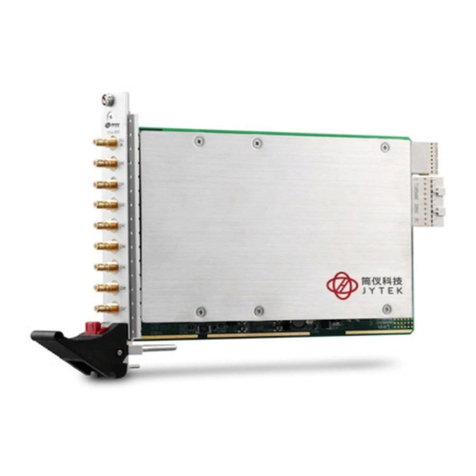
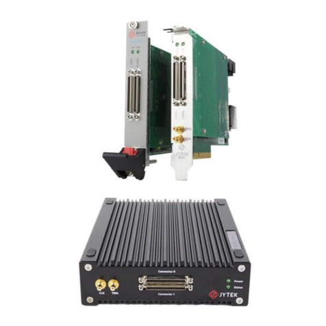
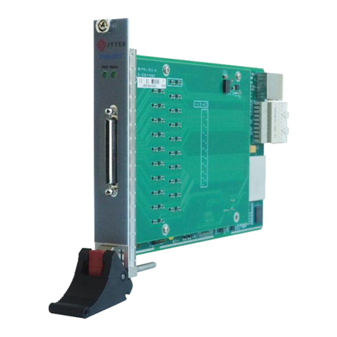
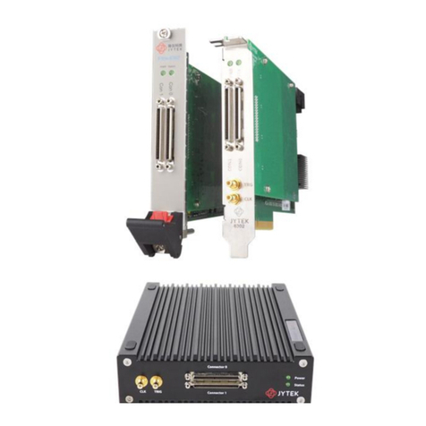
JYTEK PXI-93518 User manual

PXI-93518
8 Ports Serial
Communication Modules
User’s Manual
User Manual Version: V1.0.0
Revision Date: Nov 10, 2021

© Copyright 2021 Shanghai Jianyi Technology Co., Ltd
All Rights Reserved.
Manual Revision 1.0: Nov 10, 2021
The information in this document is subject to change without prior notice in order
to improve reliability, design and function and does not represent a commitment on
the part of the manufacturer.
In no event will the manufacturer be liable for direct, indirect, special, incidental, or
consequential damages arising out of the use or inability to use the product or
documentation, even if advised of the possibility of such damages.
This document contains proprietary information protected by copyright. All rights
are reserved. No part of this manual may be reproduced by any mechanical,
electronic, or other means in any form without prior written permission of the
manufacturer.
Trademarks
PXI-93518 are registered trademarks of JYTEK, Windows 7, Windows 10 are
registered trademarke of Microsoft- Corporation. Intel@ is a registered trademark of
Intel Corporation.Other product names mentioned herein are used for identification
purposes only and may be trademarks and/or registered trademarks of their
respective companies.

Table of Contents
1. Introduction............................................................................................................... 1
1.1 PXI-93518 Overview ....................................................................................... 1
1.1.1 What is the PXI-93518........................................................................... 1
1.1.2 PXI-93518 Features............................................................................... 1
1.1.3 PXI-93518 Connector Pin Assignment...................................................3
2. Installation................................................................................................................. 5
2.1 What You Have................................................................................................. 6
2.2 Unpacking.........................................................................................................6
2.3 Installation Procedure...................................................................................... 6
2.4 Hardware Configuration...................................................................................7
2.5 Software Installation........................................................................................ 7
2.5.1 Windows 7 Installation..........................................................................7
Figure 1 RS-422 Functional Structure..................................................................2
Figure 2 RS-485 Functional Structure..................................................................2
Figure 3 RS-232 Functional Structure..................................................................3
Figure 4 Connector DB62.................................................................................... 5
Figure 5 Device Manager.....................................................................................7
Figure 6 Update Driver Software.........................................................................8
Figure 7 Find Driver Software..............................................................................8
Figure 8 Select Driver Software...........................................................................9
Figure 9 Driver Updated Successfully..................................................................9
Figure 10 The board be recognized...................................................................10
Figure 11 The ports be recognized....................................................................10
Table 1 PXI-93518 Connector Pin Assignment....................................................4
Table 2 Notes to Legend in the Pin Definitions...................................................5

PXI-93518 | jytek.com | 1
1. Introduction
1.1 PXI-93518 Overview
1.1.1 What is the PXI-93518
PXI-93518 is an eight ports serial communication module, compatible with RS-422,
RS-485 and RS-232 standards, with fast transient voltage suppression protection
circuit. This protector can effectively suppress lightning and ESD, provide 600W
lightning surge protection power for each line, as well as surge voltage and transient
overvoltage generated on the line for various reasons, and the very small inter pole
capacitance ensures the high-speed transmission of RS-422 / RS-485 / RS-232
interface.
1.1.2 PXI-93518 Features
Eight RS-422 / 485 / 232 communication ports
Baudrate, data bit length, stop bit length (1 or 2 stop bits) and parity mode can
be set
Baud rate:
1. RS-422 and RS-485 support up to 921.6k bps;
2. RS-232 supports up to 115,200 bps.
Receiving circuit with pull-down resistor
Standard serial port operation mode
All ports adopt photoelectric isolation and ± 15kV surge protection
120Ω terminal resistance matching
Operation System Compatibility: Windows 7/ 10
Operating temperature: -40℃~+85℃
Relative Humidity: 0~90%

PXI-93518 | jytek.com | 3
Figure 3 RS-232 Functional Structure
1.1.3 PXI-93518 Connector Pin Assignment
DB62 female connector pin assignment for the PXI-93518.
Pin
RS-232
RS-422
RS-485
Port #
3
OUT1+
A1
Port1
2
OUT1-
B1
50
IN1+
49
IN1-
26
TX1
25
RX1
54
GND
5
OUT2+
A2
Port2
4
OUT2-
B2
48
IN2+
47
IN2-
24
TX2
23
RX2
53
GND
8
OUT3+
A3
Port3
7
OUT3-
B3
46
IN3+
45
IN3-
30
TX3

PXI-93518 | jytek.com | 4
29
RX3
52
GND
10
OUT4+
A4
Port4
9
OUT4-
B4
44
IN4+
43
IN4-
28
TX4
27
RX4
51
GND
14
OUT5+
A5
Port5
13
OUT5-
B5
62
IN5+
61
IN5-
38
TX5
37
RX5
12
GND
16
OUT6+
A6
Port6
15
OUT6-
B6
60
IN6+
59
IN6-
36
TX6
35
RX6
11
GND
19
OUT7+
A7
Port7
18
OUT7-
B7
58
IN7+
57
IN7-
42
TX7
41
RX7
6
GND
21
OUT8+
A8
Por8
20
OUT8-
B8
56
IN8+
55
IN8-
40
TX8
39
RX8
1
GND
Table 1 PXI-93518 Connector Pin Assignment

PXI-93518 | jytek.com | 5
RS-232
RX <1..8>
Receive Data
TX <1..8>
Transmit Data
RS-422
OUT+
<1..8>
Transmit Data Positive
OUT-
<1..8>
Transmit Data Negative
IN+ <1..8>
Receive Data Positive
IN- <1..8>
Receive Data Negative
RS-485
A <1..8>
Data Signal Positive
B <1..8>
Data Signal Negative
Table 2 Notes to Legend in the Pin Definitions
Figure 4 Connector DB62
2. Installation
This chapter describes the configurations of the serial communication module. The
contents in the package and unpacking information that the user should be aware of
are described in the beginning.

PXI-93518 | jytek.com | 6
2.1 What You Have
In addition to this User's Manual, the package includes the following items:
PXI-93518 Serial Communication Interface Module
DB62 Connector
2.2 Unpacking
Your serial communication module contains sensitive electronic components that
can be easily damaged by static electricity.
The module should be done on a grounded anti-static mat. The operator should be
wearing an anti-static wristband, grounded at the same point as the anti-static mat.
Inspect the module carton for obvious damage. Shipping and handling may cause
damage to your module. Ensure there are no shipping and handling damages on the
module before processing.
After opening the module carton, remove the system module and place it only on a
grounded anti-static surface component side up.
Again inspect the module for damage. Press down on all socket IC's to ensure they
are properly seated. Do this only with the module placed on a firm flat surface.
Note: DO NOT APPLY POWER TO THE MODULE IF IT HAS BEEN DAMAGED.
You are now ready to install your PXI Module.
2.3 Installation Procedure
1. Turn off your PXI computer system.
2. Turn off all accessories (printer, modem, monitor, etc.) connected to computer.
3. Select a PXI slot.
4. Before handling the serial communication module, discharge any static buildup on
your body by touching the metal case of the computer. Hold the edge and do not
touch the components.
5. Position the module into the PXI slot selected.

PXI-93518 | jytek.com | 7
6. Secure the module in place of the system.
2.4 Hardware Configuration
The serial communication module has Plug and Play component, the card can
requests memory usage (I/O port locations) of the card which is assigned by
system BIOS. The address assignment is done on a board-by-board basis for all serial
communication cards in the system.
2.5 Software Installation
2.5.1 Windows 7 Installation
1. After slacing the PXI-93518 in the chassis, open the [Device manager] ,and you will
see a unknown device with question mark .
Figure 5 Device Manager
2. Right click the device, select the [update driver software] button.

PXI-93518 | jytek.com | 10
6. Now you can see the port device and eight unknown multifunction device. Use
the above method to update the driver for eight devices respectively
Figure 10 The board be recognized
7. Now the port device are all identified. Serial port number starts from the smallest
available number in the system.
Figure 11 The ports be recognized

PXI-93518 | jytek.com | 11
Note: Unload the driver before removing the board to avoid occupying the
system port resources.
Warranty Policy
Thank you for choosing JYTEK. To understand your rights and enjoy all the after-sales
services we offer, please read the following carefully.
1. Before using JYTEK‘s products please read the user manual.and follow the
instructions exactly.
2. Our repair service is not covered by JYTEK‘s guarantee in the following situations:
Damage caused by not following instructions in the User's Manual.
Damage caused by carelessness on the user's part during product
transportation.
Damage caused by fire, earthquakes, floods, lightening, pollution, other acts of
God, and/or incorrect usage of voltage transformers.
Damage caused by inappropriate storage environments such as with high
temperatures, high humidity, or volatilechemicals.
Damage caused by leakage of battery fluid during or after change of batteries by
customer/user.
Damage from improper repair by unauthorized JYTEK technicians.
Products with altered and/or damaged serial numbers are not entitled to our
service.
This warranty is not transferable or extendible.
Other categories not protected under our warranty.
3. Customers are responsible for all fees necessary to transport damaged products
to JYTEK.
Table of contents
Other JYTEK Control Unit manuals
Popular Control Unit manuals by other brands

Laserworld
Laserworld RED-1500/658 user manual

Quantum Data
Quantum Data 980 Application guide

Pentair
Pentair PROSTOP-E Installation and operation manual

Siemens
Siemens SENTRON 7KM PAC 4DI/2DO operating instructions

CLA-VAL
CLA-VAL CRL-60 Installation operation & maintenance

Shenzhen TOPWAY
Shenzhen TOPWAY LMB202ECC user manual

Raven
Raven New Holland AutoBoom XRT Calibration & Operation Manual

SMC Networks
SMC Networks VHS20 Series Operation manual

SSS Siedle
SSS Siedle FPM 611-01 Maintenance Operation Installation

Beckhoff
Beckhoff AX5721 Technical documentation

EHUOYAN
EHUOYAN YHY521X user manual

Carel
Carel UltraCella Commissioning manual