Draper STORMFORCE PT1202VSF User manual

IMPORTANT: PLEASE READ THESE INSTRUCTIONS CAREFULLY TO ENSURE THE SAFE AND
EFFECTIVE USE OF THIS PRODUCT.
GENERAL INFORMATION
These instructions accompanying the product are the original instructions. This document is part of the product, keep it
for the life of the product passing it on to any subsequent holder of the product. Read all these instructions before
assembling, operating or maintaining this product.
This manual has been compiled by Draper Tools describing the purpose for which the product has been designed, and
contains all the necessary information to ensure its correct and safe use. By following all the general safety instructions
contained in this manual, it will ensure both product and operator safety, together with longer life of the product itself.
AlI photographs and drawings in this manual are supplied by Draper Tools to help illustrate the operation of the product.
Whilst every effort has been made to ensure the accuracy of information contained in this manual, the Draper Tools policy
of continuous improvement determines the right to make modifications without prior warning.
INSTRUCTIONS FOR
1200W 230V
Variable Speed Router
Stock No.83612 Part No.PT1202VSF
STORM

1. TITLE PAGE
1.1 INTRODUCTION:
USER MANUAL FOR:
1200W 230V VARIABLE SPEED ROUTER
Stock no. 83612
Part no. PT1202VSF
1.2 REVISIONS:
As our user manuals are continually updated, users should make sure that they use the very
latest version.
Downloads are available from: http://www.drapertools.com/manuals
DRAPER TOOLS LIMITED WEBSITE: drapertools.com
HURSLEY ROAD PRODUCT HELP LINE: +44 (0) 23 8049 4344
CHANDLER’S FORD GENERAL FAX: +44 (0) 23 8026 0784
EASTLEIGH
HAMPSHIRE
SO53 1YF
UK
1.3 UNDERSTANDING THIS MANUALS SAFETY CONTENT:
WARNING! Information that draws attention to the risk of injury or death.
CAUTION! Information that draws attention to the risk of damage to the product or
surroundings.
1.4 COPYRIGHT © NOTICE:
Copyright © Draper Tools Limited.
Permission is granted to reproduce this publication for personal & educational use only.
Commercial copying, redistribution, hiring or lending is prohibited.
No part of this publication may be stored in a retrieval system or transmitted in any other
form or means without written permission from Draper Tools Limited.
In all cases this copyright notice must remain intact.
Date first published March 2016

2. CONTENTS
3
2.1 CONTENTS
PAGE CONTENT PAGE
1 TITLE PAGE
1.1 INTRODUCTION ............................................................................................... 2
1.2 REVISION HISTORY........................................................................................... 2
1.3 UNDERSTANDING THIS MANUAL ................................................................... 2
1.4 COPYRIGHT NOTICE......................................................................................... 2
2 CONTENTS
2.1 CONTENTS ........................................................................................................ 3
3 GUARANTEE
3.1 GUARANTEE ..................................................................................................... 4
4 INTRODUCTION
4.1 SCOPE ............................................................................................................... 5
4.2 SPECIFICATION ................................................................................................. 5
4.3 HANDLING & STORAGE ................................................................................... 5
5 HEALTH & SAFETY INFORMATION
5.1 GENERAL POWER TOOL SAFETY WARNINGS ................................................. 6-7
5.2 SPECIFIC SAFETY INSTRUCTIONS FOR ROUTER USE ....................................... 7-8
5.3 CONNECTION TO THE POWER SUPPLY ........................................................... 8
6 TECHNICAL DESCRIPTION
6.1 IDENTIFICATION ............................................................................................... 9
7 UNPACKING & CHECKING
7.1 PACKAGING...................................................................................................... 10
7.2 WHAT´S IN THE BOX? ...................................................................................... 10
8 PREPARING THE ROUTER
8.1 PARALLEL GUIDE FENCE ................................................................................. 11
8.2 DUST EXTRACTION PORT................................................................................. 11
8.3 DUST EXTRACTION........................................................................................... 11
8.4 FITTING THE FACE SHIELD .............................................................................. 11
8.5 FITTING & REPLACING ROUTER BITS ............................................................... 12
9 BASIC ROUTER OPERATIONS
9.1 TRIGGER SWITCH.............................................................................................. 13
9.2 VARIABLE SPEED DIAL ..................................................................................... 13
9.3 SETTING THE CUTTING DEPTH......................................................................... 13-14
9.4 PARALLEL GUIDE ROUTING ............................................................................. 14
9.5 28MM INNER - 30MM OUTER DIAMETER TEMPLATE FOLLOWER ................ 14
9.6 PIVOT ROD TRAMMEL ..................................................................................... 15
10 TROUBLESHOOTING........................................................................................................... 16
11 MAINTENANCE................................................................................................................... 17
12 EXPLANATION OF SYMBOLS
12.1 EXPLANATION OF SYMBOLS ........................................................................... 18
13 DISPOSAL
13.1 DISPOSAL.......................................................................................................... 19
DECLARATION OF CONFORMITY .....................................................................................ENCLOSED

4
3. GUARANTEE
3.1 GUARANTEE
Draper
tools have been carefully tested and inspected before shipment and are guaranteed to
be free from defective materials and workmanship.
Should the tool develop a fault, please return the complete tool to your nearest distributor or
contact Draper Tools Limited, Chandler's Ford, Eastleigh, Hampshire, SO53 1YF. England.
Telephone Sales Desk: (023) 8049 4333 or Product Help Line (023) 8049 4344.
A proof of purchase must be provided with the tool.
If upon inspection it is found that the fault occurring is due to defective materials or
workmanship, repairs will be carried out free of charge. This guarantee period covering
parts/labour is 12 months from the date of purchase except where tools are hired out when the
guarantee period is 90 days from the date of purchase. The guarantee is extended to 24 months
for parts only. This guarantee does not apply to normal wear and tear, nor does it cover any
damage caused by misuse, careless or unsafe handling, alterations, accidents, or repairs
attempted or made by any personnel other than the authorised Draper warranty repair agent.
Note: If the tool is found not to be within the terms of warranty, repairs and carriage charges
will be quoted and made accordingly.
This guarantee applies in lieu of any other guarantee expressed or implied and variations of its
terms are not authorised.
Your Draper guarantee is not effective unless you can produce upon request a dated receipt or
invoice to verify your proof of purchase within the guarantee period.
Please note that this guarantee is an additional benefit and does not affect your statutory rights.
Draper Tools Limited.

5
4. INTRODUCTION
4.1 SCOPE
This hand held power tool is ideal for shaping woodwork, cabinetry, architrave, morticing
and other associated routing work. It is intended for domestic and light commercial use only.
Any other application is considered misuse.
4.2 SPECIFICATION
Stock No. ........................................................................................................................... 83612
Part No. ..................................................................................................................... PT1202VSF
Rated voltage ........................................................................................................... 230V~50Hz
Rated input ...................................................................................................................... 1200W
Collets ............................................................................................. 6.35mm (1⁄4") & 8mm (5⁄16")
Cutter Capacity ................................................................................................................. 30mm
Plunge Stroke:
with Dust Extraction ................................................................................................. 0-38mm
without Dust Extraction ............................................................................................ 0-50mm
Speed (no load) ........................................................................................... 10,000-30,000r/min
Sound Pressure Level ................................................................................................. 84±3dB(A)
Sound Power Level .................................................................................................... 95±3dB(A)
Vibration Level ................................................................................................................ 3.6m/s²
Weight ............................................................................................................................. 3.63kg
4.3 HANDLING & STORAGE
The environment will have a negative result on its operation if you are not careful. If the air
is damp, components will rust. If the machine is unprotected from dust and debris;
components will become clogged: And if not cleaned and maintained correctly or regularly
the machine will not perform at its best.

6
5. HEALTH & SAFETY INFORMATION
5.1 GENERAL POWER TOOL SAFETY WARNINGS
WARNING: Read all safety warnings and all instructions. Failure to follow the warnings and
instructions may result in electric shock, fire and/or serious injury.
Save all warnings and instructions for future reference.
The term “power tool” in the warnings refers to your mains operated (corded) power tool or
battery-operated (cordless) power tool.
1) Work area safety
a) Keep work area clean and well lit. Cluttered or dark areas invite accidents.
b) Do not operate power tools in explosive atmospheres, such as in the presence of
flammable liquids, gases or dust. Power tools create sparks which may ignite the dust
or fumes.
c) Keep children and bystanders away while operating a power tool. Distractions can
cause you to lose control.
2) Electrical safety
a) Power tool plugs must match the outlet. Never modify the plug in any way. Do not
use any adapter plugs with earthed (grounded) power tools. Unmodified plugs and
matching outlets will reduce risk of electric shock.
b) Avoid body contact with earthed or grounded surfaces such as pipes, radiators,
ranges and refrigerators. There is an increased risk of electric shock if your body is
earthed or grounded.
c) Do not expose power tools to rain or wet conditions. Water entering a power tool
will increase the risk of electric shock.
d) Do not abuse the cord. Never use the cord for carrying, pulling or unplugging the
power tool. Keep cord away from heat, oil, sharp edges or moving parts. Damaged or
entangled cords increase the risk of electric shock.
e) When operating a power tool outdoors, use an extension cord suitable for outdoor
use. Use of a cord suitable for outdoor use reduces the risk of electric shock.
f) If operating a power tool in a damp location is unavoidable, use a residual current
device (RCD) protected supply. Use of an RCD reduces the risk of electric shock.
3) Personal safety
a) Stay alert, watch what you are doing and use common sense when operating a
power tool. Do not use a power tool while you are tired or under the influence of
drugs, alcohol or medication. A moment of inattention while operating power tools
may result in serious personal injury.
b) Use personal protective equipment. Always wear eye protection. Protective
equipment such as dust mask, nonskid safety shoes, hard hat, or hearing protection
used for appropriate conditions will reduce personal injuries.
c) Prevent unintentional starting. Ensure the switch is in the off position before
connecting to power source and/or battery pack, picking up or carrying the tool.
Carrying power tools with your finger on the switch or energising power tools that
have the switch on invites accidents.
d) Remove any adjusting key or wrench before turning the power tool on. A wrench or
a key left attached to a rotating part of the power tool may result in personal injury.
e) Do not overreach. Keep proper footing and balance at all times. This enables better
control of the power tool in unexpected situations.

7
5. HEALTH & SAFETY INFORMATION
f) Dress properly. Do not wear loose clothing or jewellery. Keep your hair, clothing and
gloves away from moving parts. Loose clothes, jewellery or long hair can be caught in
moving parts.
g) If devices are provided for the connection of dust extraction and collection facilities,
ensure these are connected and properly used. Use of these devices can reduce
dust-related hazards.
4) Power tool use and care
a) Do not force the power tool. Use the correct power tool for your application. The
correct power tool will do the job better and safer at the rate for which it was
designed.
b) Do not use the power tool if the switch does not turn it on and off. Any power tool
that cannot be controlled with the switch is dangerous and must be repaired.
c) Disconnect the plug from the power source and/or battery pack from the power tool
before making any adjustments, changing accessories, or storing power tools. Such
preventive safety measures reduce the risk of starting the power tool accidentally.
d) Store idle power tools out of the reach of children and do not allow persons
unfamiliar with the power tool or these instructions to operate the power tool.
Power tools are dangerous in the hands of untrained users.
e) Maintain power tools. Check for misalignment or binding of moving parts, breakage
of parts and any other condition that may affect the power tool’s operation. If
damaged, have the power tool repaired before use. Many accidents are caused by
poorly maintained power tools.
f) Keep cutting tools sharp and clean. Properly maintained cutting tools with sharp
cutting edges are less likely to bind and are easier to control.
g) Use the power tool, accessories and tool bits etc. in accordance with these
instructions, taking into account the working conditions and the work to be
performed. Use of the power tool for operations different from those intended could
result in a hazardous situation.
5) Service
a) Have your power tool serviced by a qualified repair person using only identical
replacement parts. This will ensure that the safety of the power tool is maintained.
5.2 SPECIFIC SAFETY INSTRUCTIONS FOR ROUTER USE.
1. Hold power tool by insulated gripping surfaces, when performing an operation where
the cutting accessory may contact hidden wiring or its own cord. Cutting accessory
contacting a "live" wire may make exposed metal parts of the power tool "live" and
could give the operator an electric shock.
2. Always wear a dust mask and ear protection when using this power tool.
3. Use only bits, which are designed for this router.
4. Use only sharp bits that are not chipped or cracked. Blunt bits will cause stalling.
5. Secure small pieces of wood firmly before working. Never hold them in your hand.
6. Danger. Keep hands away from the cutting area.
7. Secure the workpiece by means of the clamping equipment.
8. Before staring up, check that the bit is firmly positioned and secured into the collets.
9. The maximum indicated limit rotation speed of the milling bit must not be exceeded.
10. Routing must always be carried out against the direction of rotation (bit-rotation) of the
bit.
11. The bit must be running at full speed before lowering into the workpiece.

8
5. HEALTH & SAFETY INFORMATION
12. When operating the machine, take great care and always hold the router handles firmly
with both hands. Always provide for a secure footing when working.
13. Beware of the reaction torque of the machine, particularly if the bit becomes jammed in
the workpiece.
14. On completion of work, allow the machine to slide back to its initial position by
releasing the handle.
15. Make yourself familiar with your working area and be alert for possible hazards, which
you might not hear due to machine noise.
16. Caution: Allow for run down time of bit after turning router off. Wait for the machine
to come to a complete stop before removing from the workpiece.
17. Never slow the router down with your hands.
18. Do not touch the bit immediately after operation; it may be extremely hot and could
burn you.
19. Never stop the router by applying lateral pressure to the bit.
20. Do not force the router. Your router will do a better job if you take it slowly.
21. Avoid cutting nails and screws. Inspect timber and remove all nails and screws before
cutting.
22. In the event of an electrical or mechanical malfunction, immediately switch off the router
and disconnect the power lead from the mains supply, and contact Draper for assistance.
5.3 CONNECTION TO THE POWER SUPPLY
Make sure the power supply information on the machine’s rating plate are compatible with
the power supply you intend to connect it to.
This product comes supplied with a UK standard 3 pin plug fitted. It is designed for
connection to a domestic power supply rated at 230V AC.
This appliance is Class II† and is designed for connection to a power supply matching that
detailed on the rating label and compatible with the plug fitted.
If an extension lead is required, use an approved and compatible lead rated for this
appliance. Follow all the instruction supplied with the extension lead.
†Double insulated : This product requires no earth connection as supplementary
insulation is applied to the basic insulation to protect against electric shock in the event of
failure of the basic insulation.
Apart from replacing the fuse in the plug, no other electrical work is recommended on this
machine.
9
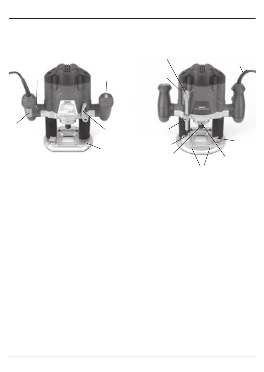
On/off trigger switch
Trigger safety button
Plunge lock lever
Additional rod locking point
(used in conjunction with 16)
Rod Locking point
Spindle lock button
Variable speed dial
6. TECHNICAL DESCRIPTION
6.1 IDENTIFICATION
Moulded plug & cable
Fine height adjustment control
Height adjustment scale
Height adjustment lock
Collet nut
Turret
Face shield anchor points

10
7. UNPACKING & CHECKING
7.1 PACKAGING
Carefully remove the router from the packaging and examine it for any sign of damage that
may have happened during shipping. Lay the contents out and check them against the parts
shown below. If any part is damaged or missing; please contact the Draper Help Line (the
telephone number appears on the Title page) and do not attempt to use the router.
The packaging material should be retained at least during the guarantee period: in case the
machine needs to be returned for repair.
Warning! Some of the packaging materials used may be harmful to children. Do not leave
any of these materials in the reach of children.
If any of the packaging is to be thrown away, make sure they are disposed of correctly;
according to local regulations.
7.2 WHAT´S IN THE BOX?
As well as the router; there are several parts not fitted or attached to it.
Spanner
30mm template follower
Rods
Shield
Dust extraction port
Dust extraction port machine screws
Parallel guide fence
Shields nuts, washer and bolt
4mm hex. key
Rods to guide fence washers and bolts.
Collets 1 x 6.35mm (1⁄4"),1 x 8mm (5⁄16")
Pivot rod trammel

11
8 PREPARING THE ROUTER
NOTE: Remove the plug from the socket before carrying
out adjustment, servicing or maintenance.
8.1 PARALLEL GUIDE FENCE - FIG. 1
Attach the two face plates to the parallel guide
fence with the four machine screws supplied.
Insert screw through washer . Secure the
rods onto the guide fence with the screw assembly.
8.2 DUST EXTRACTION PORT - FIGS. 2 - 3
The majority of operations will require the dust
extraction to be fitted, however some operations will be
impossible with the port fitted. These require
appropriate safety equipment to be worn.
Fit the dust extraction port into the recess. Pass the
two machine screws up through the base and into
the nuts in the port. Secure the port without damaging
the plastic parts by over tightening the machine screws.
NOTE: With the dust extraction port fitted, the plunger
stroke is slightly reduced.
8.3 DUST EXTRACTION
Inhalation of dust particles can be detrimental to
health. The dust outlet must be connected with a
dust extraction machine.
NOTE: Due to the outlet diameter, a size adaptation
may be necessary.
All wood dust (including dust from composites like
chipboards and fibre boards etc) is hazardous to health;
it can affect the nose, the respiratory system and the
skin. For example MDF (medium density fibreboard)
which contains formaldehyde is a known carcinogen. In
addition to the above measures a correctly fitted dust
mask, suitable for the activity and in accordance to the
relevant standard, must be worn. For work activities
involving exposure to fine wood dust a mask rated to at
least FFP2 should be used.
FIG.1
FIG.2
FIG.3
8.4 FITTING THE FACE SHIELD - FIG. 3b
The face shield (chip guard) helps to protect the user
from any debris that may be thrown from the
workpiece. Fix face shield onto sole plate using
nuts, bolts and washers making sure the fixings are
facing the outside of the machine. FIG.3b

12
8 PREPARING THE ROUTER
8.5 FITTING & REPLACING ROUTER BITS -
FIG. 4
This router is designed for use with ¼” and 8mm
shank router bits only.
WARNING: Use bits of the correct shank diameter
suitable for the speed of the tool.
Selection of the correct router bit, suitable for the
intended application is vital. Seek guidance if
uncertain of selection.
Press the spindle lock button and unscrew the
collet nut using the spanner supplied.
NOTE: Take care not to loose the spring behind the
collet.
Choose from the collets provided, the appropriate size
for the cutters shank (¼") 6.35mm or 8mm (5⁄16"). If the
size is not known insert the bit into the collet. The
collet which offers a machine fit to the shank is the
correct one to use. Do not force the bit into a collet.
Replace the spring and place the collet into the
spindle before loosely replacing the nut .
Slide in the bit allowing approx. 5-10mm overhang
before tighten the collet nut (observe the router bit’s
manufacturers instructions for more specific
information).
NOTE: Ensure at least 75% of the shank is inside the
collet. Do not tighten the collet with no bit fitted as
this will cause damage.
Do not overtighten the collet nut.
WARNING: Take care when handling the cutter bits as
they are extremely sharp.
When cutting is complete remove the bit before
cleaning and storing it in a safe place.
FIG.4

13
NOTE: Remove the plug from the socket before carrying
out adjustment, servicing or maintenance.
9.1 TRIGGER SWITCH - FIG. 5
The router is fitted with a safety lock off switch to
prevent accidental starting. Press and hold lock button
. Pull trigger and the router will start.
FIG.5
NOTE: Cutting speed depends on material, cutter size,
cutting depth etc. Larger router bits will require a
slower speed. For more detailed information refer to a
routing/woodworking book.
9.3 SETTING THE CUTTING DEPTH - FIGS. 7 - 9
With a suitable router bit fitted place the router on to
the workpiece. Rotate the turret to the lowest
position. Slowly plunge the router until the bit just
touches the workpiece. Lock the router in this position
with the plunge lock lever .
Ensure the height adjustment lock is not tight and
lower the rod until it touches the turret.
If necessary turn the fine height adjustment control
to align the nearest digit on the scale against the
pointer .
Take note of the setting before raising the rod upward
to set the plunge depth (the difference between the
two measurements) and securely tighten the height
adjustment lock . eg. scale reads 23. After
adjustment reads 33, the plunge depth will be 10mm.
Release the plunge lock lever and raise the router back
to full height. Rotate the turret round several positions
and the router is set up ready to begin work.
FIG.7
FIG.6
9.2 VARIABLE SPEED DIAL - FIG. 6
The variable speed dial is marked 1 to 7 and correspond:
9. BASIC ROUTER OPERATIONS
SETTING APPROX.SPEED (r/min)
000,011
000,412
000,813
005,224
005,425
000,826
000,037
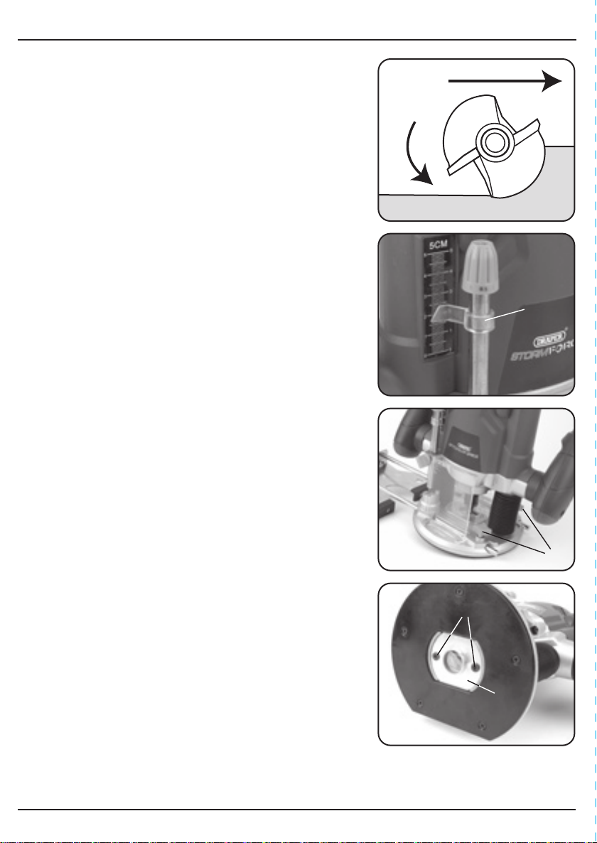
Direction of Feed
Direction
of Rotation
WORKPIECE
14
9. BASIC ROUTER OPERATIONS
When beginning to cut, plunge the cutter slowly to the
first depth and proceed with the cut. Take a second pass
at the next step down on the turret and continue until
the full depth is achieved.
Regulate the depth of the cut and speed of feed to
ensure no strain is put on to the cutter or motor,
however if the speed is too slow, burn marks may
appear on the workpiece.
NOTE: The direction of rotation is marked on the metal
casting above the spindle stop mechanism. Travelling
along a workpiece in the wrong direction will cause the
bit to pull and bounce, leading to a poor finish and
possible damage.
If, after the full depth has been routed, further material
removal is necessary lock the router in the plunged
position. Rotate the fine height adjustment control .
Turning the fine adjustment anti-clockwise will
increase the plunge depth. One complete turn is
equivalent to 1mm plunge depth. When set, take
another pass along the cut.
NOTE: Remove the plug from the socket before carrying
out adjustment, servicing or maintenance.
9.4 PARALLEL GUIDE ROUTING - FIG. 10
Ensure the edge along which the guide is going to
travel is smooth and true as any inconsistencies will
translate into the cut.
Pass the parallel guide rods through the four points in
the router’s base and secure in place with lock knobs
.
When using the parallel guide an even pressure should
be applied to each face except on a leading/trailing
edge of a workpiece. When leading on to a workpiece
apply the pressure to the forward face until both faces
are on. When trailing off a workpiece apply the
pressure to the rear face until the cut is complete.
9.5 28mm INNER - 30mm OUTER DIAMETER
TEMPLATE FOLLOWER - FIG. 11
For detailed information on templates refer to a
routing/woodworking book.
Lay the template follower into the recess. Ensure
the template follower faces downward and secure with
the two countersunk screws .
WARNING: Whilst this router is capable of cutting
kitchen worktops, it should be noted that this is not a
professional machine and therefore its tolerances and
performance are not as accurate as a professional
machine.
FIG.8
FIG.9
FIG.10
FIG.11

15
9. BASIC ROUTER OPERATIONS
NOTE: Remove the plug from the socket before carrying
out adjustment, servicing or maintenance.
9.6 PIVOT ROD TRAMMEL - FIG. 12
Secure one of the parallel guide rods into the rear
channel. Remove the rod locking knob from the
front channel and secure it into the additional rod
locking point. Loosen the wing nut and slide the
trammel on to the rod end. Adjust the point height
to suit before locking the wing nut. Adjust the distance
between the router bit and pivot point.
FIG.12

Motor
does not start
1. Fuse
3. Other
1. Replace/reset time delay
fuse or circuit breaker
2. Have brushes replaced by
authorised service agent
3. Return to authorised
service agent
2. Brushes worn
Machine vibrates 1. Router bit not suitable
for application
3. Incorrect direction of
travel
1. Seek guidance on bit
selection
2. Stop machine. When
stopped, replace with a
sharp bit
3. Change direction of
travel
2. Router bit blunt
Bit will not cut 1. Attempting to remove
excess material
3. Incorrect direction of
travel
1. Reduce plunge depth
2. Stop machine. When
stopped, replace with a
sharp bit
3. Change direction of travel
2. Router bit blunt
16
10. TROUBLESHOOTING
PROBLEM POSSIBLE CAUSE REMEDY
NOTE: Remove the plug from the socket before carrying out adjustment, servicing or
maintenance.

17
11. MAINTENANCE
Regular inspection and cleaning reduces the necessity for maintenance operations and will
keep your tool in good working condition.
The motor must be correctly ventilated during tool operation. For this reason avoid blocking
the air inlets. After use disconnect the tool from the power supply and vacuum the
ventilation slots.
If the replacement of the supply cord is necessary, this has to be done by the manufacturer or
his agent in order to avoid a safety hazard.
Remove the plug from the socket before carrying out adjustment, servicing or maintenance.

18
12. EXPLANATION OF SYMBOLS
12.1 EXPLANATION OF SYMBOLS
Warning!
Wear dust mask.
Warning!
Wear ear defenders.
WEEE
Do not dispose of Waste Electrical
& Electronic Equipment in with
domestic rubbish
Class II construction
(Double insulated).
Warning!
Read the instruction manual
Warning!
Wear suitable eye/face
protection.
Reference to
‘Welding’
removed from
eye/face
protection icon
wording.
05/08/16 CH

19
13. DISPOSAL
13.1 DISPOSAL
- At the end of the machine’s working life, or when it can no longer be repaired, ensure
that it is disposed of according to national regulations.
- Contact your local authority for details of collection schemes in your area.
In all circumstances:
• Do not dispose of power tools with domestic waste.
• Do not incinerate.
• Do not abandon in the environment.
• Do not dispose of WEEE*
as unsorted municipal waste.
* Waste Electrical & Electronic Equipment.

CONTACTS
- DRAPER TOOLS LIMITED,
Hursley Road, Chandler's Ford,
Eastleigh, Hampshire. SO53 1YF. U.K.
- Help Line: (023) 8049 4344
- Sales Desk: (023) 8049 4333
- General Enquiries: (023) 8026 6355
- Service/Warranty Repair Agent
For aftersales servicing or warranty repairs, please
contact the Draper Tools Help Line for details of an
agent in your local area.
YOUR DRAPER STOCKIST
RDCH0816
drapertools.com
This manual suits for next models
1
Table of contents
Popular Industrial Equipment manuals by other brands

ABB
ABB HT603850 Operation manual

SMC Networks
SMC Networks ZKJ Series instruction manual

Hypertherm
Hypertherm XPR170 Preventive maintenance program

Endress+Hauser
Endress+Hauser Soliwave FDR16 Brief operating instructions

Scheppach
Scheppach HP2500S Translation of original instruction manual

Siemens
Siemens SIWAREX WL260 SP-S AA operating instructions


