HAEMMERLIN MAXIAL PREMIUM User manual

1
TECHNICAL INSTRUCTIONS FOR USE
MAXIAL
PREMIUM
EXCELLIUM
EXPERT
Haemmerlin - CDH Group
28, rue de Steinbourg - BP 30045 - 67701 SAVERNE CEDEX - FRANCE
Tel. + 33 (0)3 88 01 85 00 - Fax + 33 (0)3 88 71 18 01
welcome@haemmerlin.com –www.haemmerlin.com
Material conform
to the guidelines
412700000
Index D of 05/02/2021

2
INDEX
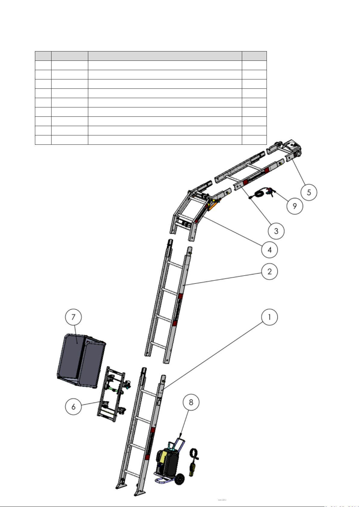
MAXIAL PREMIUM 175 basic composition ................................................................................ 3
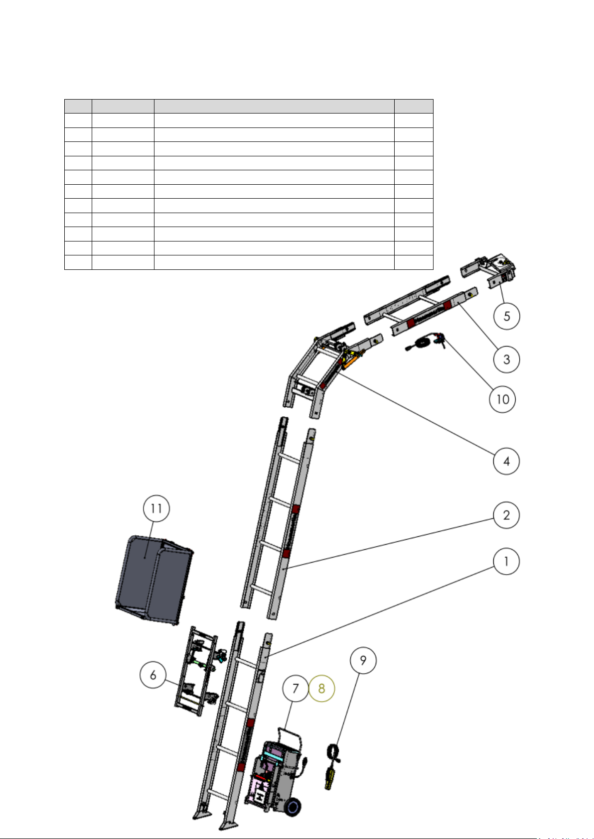
MAXIAL EXCELLIUM 200 basic composition..... ....................................................................... 4
MAXIAL EXPERT 250 basic composition .................................................................................. 5
Sample EC Declaration of Conformity ....................................................................................... 6
Guarantee conditions ................................................................................................................. 7
List of all components ................................................................................................................. 8-9
Technical specifications .............................................................................................................. 10
General characteristics ............................................................................................................... 11-12
Precautions to be taken during installation ................................................................................. 12-13
Safety markings .......................................................................................................................... 14
Installation and safety instructions .............................................................................................. 15-20
Installation of electric winches:
- Winch 175 CA for Maxial Premium ........................................................................................ 21-23
- Winch 200/250 ABM-VF for Maxial Excellium / Expert .......................................................... 24-26
Installation of the upper limit switch on the ladder ...................................................................... 27
Installation of the guide hooks for the upper limit switch electrical cable .................................... 28-29
Installation of the lifting cable ...................................................................................................... 30-32
Installation and use of accessories:
- Roofer platform ....................................................................................................................... 33
- Universal platform .................................................................................................................. 34
- Double tipping bin .................................................................................................................. 35-40
- Tipping skip ............................................................................................................................ 41-43
- Horizontal/vertical sheet carrier .............................................................................................. 44
- Renovation platform ................................................................................................................ 45-49
Inclined shoring ........................................................................................................................... 50
Examples of inclined installations of the hoist on the façade of a building .................................. 52
Installation and use of shoring accessories:
- Base ladder prop 2 to 3m ....................................................................................................... 52-53
- Extension prop 2m .................................................................................................................. 53
- Bumper prop 1.5 to 2.5m ........................................................................................................ 54-55
- Pair of headboard props ......................................................................................................... 56
- Complete trestle with fixing clamps ........................................................................................ 57
Vertical anchoring ........................................................................................................................ 58
Examples of vertical installations of the hoist on the façade of a building ................................... 59
Installation and use of accessories for anchoring against a building:
- Enclosure clamp ...................................................................................................................... 60-61
- Balcony clamp ......................................................................................................................... 62-63
- Mooring cylinder ...................................................................................................................... 64-66
Vertical installation against the façade of a building using clamps .............................................. 67-68
Examples of vertical installations of the material hoist against scaffolding .................................. 69
Installation and use of accessories for anchoring against scaffolding:
- Tube, couplers and VE fixing clamps ....................................................................................... 69-71
Vertical mounting against scaffolding using VE fixing clamps ...................................................... 72-73
Dismantling the hoist ..................................................................................................................... 74-75
Regulations and safety instructions ............................................................................................... 76-79
Maintenance .................................................................................................................................. 79-81
Repairing Maxial electric winches ................................................................................................. 82-83
Electrical diagram of 175CA winch for Maxial Premium ............................................................... 84
Electrical diagram of 200/250 ABM/VF winches for Maxial Excellium and Maxial Expert ............ 85-86
Guarantee form and/or after sales service .................................................................................... 87

3
Basic composition MAXIAL PREMIUM 175
Rep.
Item code
Name
Qty
1
312390101
Base ladder 2m PS with quick bolts
1
2
312261901
Extension ladder 2m PS with quick bolts
3
3
312262201
Extension ladder 1m PS with quick bolts
1
4
312762401
Pre-angled knee joint from 30 to 60° (1.20m)
1
5
312772601
Headboard (0.30m)
1
6
312793401
Standard trolley
1
7
312793601
Roofer platform with 2 side panels
1
8
312370401
Winch 175 CA Cable Ø5 leng. 42m with remote control
1
9
312390601
Detachable upper limit switch 24V (20m cable)
1

4
Basic composition MAXIAL EXCELLIUM 200
Rep.
Item code
Name
Qty
1
312390101
Base ladder 2m PS with quick bolts
1
2
312261901
Extension ladder 2m PS with quick bolts
3
3
312262201
Extension ladder 1m PS with quick bolts
1
4
312762401
Pre-angled knee joint from 30 to 60° (1.20m)
1
5
312772601
Headboard (0.30m)
1
6
312793401
Standard trolley
1
7
312800001
Winch 200 ABM-VF -Cable Ø6 leng. 45m
1
8
216007000
Lifting cable Ø6 length 45m AB
1
9
312690501
Detachable remote control 24V (6m cable)
1
10
312390601
Detachable upper limit switch 24V (20m cable)
1
11
312793601
Roofer platform
1

5
MAXIAL EXPERT 250 basic composition
Rep.
Item code
Name
Qty
1
312762001
Base ladder 2m PR with quick bolts
1
2
312761901
Extension ladder 2m PR with quick bolts
3
3
312762201
Extendible ladder 1m PR with quick bolts
1
4
312762501
Double ply knee joint from 0 to 60° (1.20m)
1
5
312772601
Headboard (0.30m)
1
6
312793401
Standard trolley
1
7
312800001
Winch 200 ABM-VF - Cable Ø6 leng. 45m
1
8
216007000
Lifting cable Ø6 length 45m AB
1
9
312690501
Detachable remote control 24V (6m cable)
1
10
312390601
Detachable upper limit switch 24V (20m cable)
1
11
312694601
Universal platform
1

6
SAMPLE EC DECLARATION OF CONFORMITY
The manufacturer, Haemmerlin CDH Group
28, rue de Steinbourg - BP30045 - 67701 SAVERNE,
declares that the machine below:
HOIST
CASTOR STEEL
MAXIAL COMPACT
MAXIAL PREMIUM
MAXIAL EXCELLIUM
MAXIAL EXPERT
Serial number: ………………………… ...
complies with the provisions of the European Machinery Directive 2006/42/EC
and the national legislation implementing it.
It must be used in compliance with all the technical instructions for assembly,
operating and maintenance manual enclosed with the machine.
Signed in Saverne, on ................
Name: Christian Pitisi
Title: Head of Establishment - Industrial Director
Signature:
Contact person for technical documentation:
Consultancy agency

7
GUARANTEE CONDITIONS
The guarantee period for the hoists and their components is 1 year from the date of delivery of the machine
to the user, the date of the invoice being the proof.
The validity of this guarantee is directly linked to the way in which the hoist is used, according to the
instructions for use and maintenance contained in the assembly, operating and maintenance manual.
We advise the user to take care of the maintenance of the mechanical components of the hoist
Similarly, the user is warned that the electrical parts are excluded from this guarantee, except for
components that have obvious manufacturing defects.
Replacement of parts is only allowed with the prior approval of Haemmerlin.
In the case of defective or faulty parts, Haemmerlin undertakes to supply replacement parts free of charge
for the duration of the guarantee period.
This guarantee does not cover:
-normal wear and tear
-damage caused by misuse or improper handling by the user or a third party
-damage caused by transport or handling
-improper maintenance by the user or a third party
-use of an unsuitable lubricant or grease by the user or a third party
-the discovery of an unauthorised intervention on components
-arbitrary dismantling of the machine or its parts
-repairs carried out by unqualified personnel
-use of non-original-brand spare parts by the user or a third party
-shocks, falls, fires, floods, and/or other accidental events, even of a geological or atmospheric
nature,
Haemmerlin reserves the right to modify the hoists and the contents of the technical
manuals at any time with no obligation to update the previous hoists and manuals.
For all guarantee claims, the user must provide a dated proof of purchase, delivery note or invoice, and the
completed guarantee / service form.
This guarantee / service form is on the last page of this manual.
Without proof of purchase and a guarantee / service form, Haemmerlin will not be able to apply the
guarantee.
The information that you provide on this guarantee / service form is required for Haemmerlin to understand
your problem and make an accurate diagnosis.
In the case of a telephone call, the user must provide the Haemmerlin contact person with all of the
information requested on the guarantee / service form.
If the problem cannot be diagnosed and/or solved over the telephone, the hoist must be returned to
Haemmerlin at the following address:
Haemmerlin - CDH Group
28, rue de Steinbourg - BP 30045 - 67701 SAVERNE CEDEX - FRANCE
ATELIER F1 / Levage
Haemmerlin will not bear any costs resulting directly or indirectly from the immobilisation
of the hoist

8
LIST OF ALL COMPONENTS OF THE HOIST
Name
Item code
Weight
(kg)
Base ladder 2m PS with quick bolts
312390101
11.5
Extension ladder 2m PS with quick bolts
312261901
9.9
Extension ladder 1m PS with quick bolts
312262201
5.6
Extension ladder 0.5m PS with quick bolts
312262101
4
Base ladder 2m PR with quick bolts
312762001
13.15
Extension ladder 2m PR with quick bolts
312761901
11.1
Extendible ladder 1m PR with quick bolts
312762201
6.3
Extension ladder 0.5m PR with quick bolts
312762101
4.2
Pre-angled knee joint from 30 to 60° (1.20m)
312762401
11.8
Double ply knee joint from 0 to 60° (1.20m)
312762501
15.18
Headboard (0.30m)
312772601
6.7
Quick bolt
312691701
0.2
Standard trolley
312793401
15.97
Roofer platform
312793601
27.16
Front panel
312793701
4.5
Universal platform
312694601
29
Renovation platform
312795501
39.7
Horizontal and vertical sheet carrier
312795601
21.7
Double tipping bin
312392401
48.6
Tipping skip
312392501
25.4
Winch 175 CA - Cable Ø5 leng. 42m + Remote control (3m cable)
312370401
45
Winch 200/250 ABM-VF - Cable Ø6 leng. 45m
312800001
76.3
Detachable upper limit switch 24V (20m cable)
312390601
2
Complete remote control 24V (6m cable)
312690501
2
Trestle with fixing clamps
312767601
4.7
Base ladder prop 2 to 3m
312268001
11
Extension prop 2m
312268101
3
Pair of headboard props adjustable from 1.1 to 2m
312797801
11
Bumper prop adjustable from 1.5 to 2.5m
312697901
7.5
Enclosure clamp
312668001
10
Balcony clamp
312668101
11
Mooring cylinder from 0.70 to 1m
312072101
6
Mooring cylinder from 1m to 1.70m
312072201
7.8
Scaffolding tube Ø49 length 2m
312072601
7.7
Orthogonal coupler
312072401
1.3
Hinged coupler
312072301
1.5
Fixing clamp
312073001
0.5
VE fixing clamp
312073101
0.7
Electrical extension cord for power supply 15m
312790701
4.5
Remote control electrical extension cord 5m
319120001
2.4
Remote control electrical extension cord 15m
312790601
3.4

9
The components of the hoist that weigh more than 25kg must be handled by at least two
people.
Prolongateur électrique de télécommande 25m 319121001 4,4
Prolongateur électrique de fin de course haut 20m 312072501 3,4
Câble de levage D6 longueur 45mAB 312799701 6,2
Câble de levage D6 longueur 62mAB 312799801 8,6
Câble de levage D6 longueur 82mAB 312799901 11,3
Lot de 3 crochet de guidage du câble électrique de FDC haut 312703001 0,07

10
TECHNICAL SPECIFICATIONS
This equipment is a category III construction site hoist designed and built in accordance with the European
regulations currently in force, and more particularly the amended Machinery Directive 2006/42/EC. This
hoist is not designed to be used in ATEX or explosive areas.
This machine is listed in the decree of 1 March 2004. It must be checked in accordance with the regulations
when it is first put into service. The same applies in the case of major alterations or repairs. This verification
must include:
-The suitability test: The “suitability test for a hoist" refers the test which consists of verifying that the
hoist is suitable for the work which the user intends to carry out and for the risks to which the
workers are exposed, and that the operations planned are compatible with the conditions of use of
the hoist as defined by the manufacturer.
-The assembly and installation test: The “assembly and installation test for a hoist" refers to the test
to ensure that the hoist is assembled and installed safely in accordance with the manufacturer's
instructions.
-The static test: The static tests must be carried out with a coefficient of 125% of the
maximum useful load (MUL).
-The Dynamic test: The dynamic tests must be carried out with a coefficient of 110% of the
maximum useful load (MUL).
As hoists are subject to frequent movement, they are exempt from the obligation to renew the tests after
each dismantling and reassembly, provided that they are verified and approved every 6 months. These
provisions are derived from regulations aimed at the heads of user establishments. This biannual
verification must include:
-The suitability test,
-The assembly and installation test,
-The state of conservation test: The “state of conservation test for the hoist" means the test to check
the good state of conservation of the components of the hoist during the whole period of its
installation.
-The static test,
-The dynamic test,
The maintenance logbook must be kept up to date by the head of the establishment, according to article
R233-12 of the French labour code, in order to ensure that the maintenance operations required for
operating the hoist are performed in conditions that preserve the safety and health of workers.
All the reports of interventions must be recorded in this maintenance book to contribute to the essential
maintenance and the proper management of the hoist until its disposal.
The head of the establishment is responsible for the application of the user regulations in force.
Before using this hoist, it is essential, for the safety of the equipment and its efficiency, to read over this
technical manual and to follow all its instructions. This technical manual must be kept with the machine and
be available to the operators for the entire lifespan of the hoist. Additional copies can be supplied on
request.
HAEMMERLIN accepts no liability for any consequences arising from the use or installation of the lift that is
not provided for in these operating instructions; as well as the consequences of disassembly, modifications
or replacement of parts or components from other sources without written agreement.
At the time of purchase, the purchaser must ensure the integrity of the structure.

11
GENERAL CARACTERISTIQUES
Name
MAXIAL
PREMIUM
EXCELLIUM
EXPERT
Payload
175 kg
200 kg
250 kg
Maximum working height
20 m
30 m
40 m
Hoisting Speed
22 m/min
28 m/min
28 m/min
Winch
Single-phase
electrical
Single-phase
electrical
Single-phase
electrical
Supply voltage
220V50Hz
220V50Hz
220V50Hz
Engine power
1.1kw
1.5kw
1.5kw
Starting current at maximum load
9.5A
16A
16A
Continuous current at maximum load
8.2A
7.6A
7.6A
Service factor
60%
60%
60%
Protection
IP44
IP54
IP54
Minimum power of a generator unit
4.5 KVA
5.5 KVA
5.5 KVA
Cable diameter
5 mm
6 mm
6 mm
Cable length
42 m
45/62 m
45/62/82 m
CRM (minimum load at cable breakage)
1880 kg
2210 kg
2210 kg
Cable material
Galvanised steel
Number of cable strands
7x19
6x19
Central cable core
Metallic
Textile
Cable end 1
Crimped end Ø14
mm
Prepared and welded
Cable end 2
Loop 27x18 mm
Cable drum diameter
120 mm
124 mm
124 mm
Handling wheels
2 wheels / winch
2 wheels / winch
2 wheels / winch
Low voltage control 24V with detachable remote
control. Cable
length 3m, with 5, 15 and 25m extensions available.
Box with 3 buttons: Up (white), Down (black) and
Emergency Stop (red)
Operates by pressing the buttons, the brake
operates when the buttons are released. Protection
IP65
YES
YES
YES
Limitation of movement:
- by upper limit switch 24V flanged on the ladder by
lower limit switch/anti slack rope 24V integrated in
the winch
YES
YES
YES
Acoustic power
75.6dB(A)
68.3dB(A)
68.3dB(A)
Standard trolley
YES
YES
YES
Basic accessory
Roofer platform
with 2 side panels
Roofer platform
with 2 side panels
Universal platform
with 3 panels
Platform dimensions (Width x Depth x Height)
558x445x794
558x445x795
700x444xx853
Volume of the platform in inclination
0.197m3
0.197m3
0.265m3

12
Volume of the platform, vertical with front panel
0.110m3
0.110m3
0.138m3
Base ladder 2m with hinged shoes
Standard profile
Standard profile
Heavy duty profile
Ladder 0.5 m
Standard profile
Standard profile
Heavy duty profile
Ladder 1 m
Standard profile
Standard profile
Heavy duty profile
Ladder 2 m
Standard profile
Standard profile
Heavy duty profile
Knee joint (1.20m)
Pre-welded 30 to
60°
Pre-welded 30 to
60°
Double ply 0 to 60°
Headboard (0.30m)
Yes
Yes
Yes
Fast assembly with quick bolts
Yes
Yes
Yes
The hoisting, shoring and anchoring accessories and additional elements listed in the
catalogue are all optional.
In order to improve its products, HAEMMERLIN reserves the right to make changes to the
materials at any time.
PRECAUTIONS TO BE TAKEN DURING INSTALLATION
-The assembly area must be marked out and the equipment must be stored properly without
obstructing the movement of third parties and allowing the smooth running of the site.
-Set up the workstation so that the operator has full visibility of the entire trajectory of the moving
parts. The work area must be well lit to ensure a good view of the entire path of the load to be
hoisted.
-Make sure that it is not possible to be within five metres of a live power line. Take into account the
length of materials handled and hoisted.
-Make sure that the ground can support the load at the support point of the hoist when it is at
maximum load. The anchoring must be stable, solid and durable.
-The hoist shall be installed so that, during ascent or descent, the moving part of the hoist cannot
collide with other moving bodies or with the building or structure against which it is installed.
-Verify that the length of the lifting cable is greater than twice the height of the high unloading
point and that once the machine is installed with the mobile equipment in the lowered
position, there are at least 3 turns of cable left wound around the winch drum. Verify the
general condition and the winding of the lifting cable around the drum. It must always be perfectly
wound around the drum to avoid deteriorating. It must be replaced if it shows tears or crushing. It is
strictly forbidden to repair a lifting cable using couplers or cable ties! See the chapter on cable
maintenance on pages 93-94.
GROUND PRESSURE UNDER MAXIMUM LOAD
HEIGHT OF THE
LADDER
MAXIAL
PREMIUM
EXCELLIUM
EXPERT
H10m
387daN
440daN
500daN
H15m
413daN
466daN
529daN
H20m
464daN
516daN
586daN
H30m
567daN
643daN
H40m
700daN
P

13
-Read the instructions on the sheets and labels attached to the hoist.
-Ensure that the building or structure against which the machine is to be installed is capable of
withstanding the reaction forces due to the passing of the loaded mobile crew.
-Ensure that the loading and unloading areas and the area around the installation are clean.
-Mark out the danger zone with a physical system. All workplaces must be protected by guardrails in
accordance with current regulations, consisting of two horizontal elements. One should be at a
height of between 1 and 1.2m, the other at a height of about 0.5m. These elements should be
marked in an eye-catching colour (e.g. red and white). The marked out space must protect an area
of a width corresponding to the largest load envisaged, for a distance of at least 1.40m.
-To ensure the protection of the people who install the equipment as well as the users.
-In all cases, the person or persons installing the machine at a height must wear a safety harness
with a fall arrest system, anchored to a suitable part of the building.
The structure and equipment of the hoist must not be used as an anchoring point for the
safety harness.
-It is strictly forbidden to transport people.
-It is strictly forbidden to access the transport devices.
-Never overload the transport device.
-Mark out and protect the risk area in a suitable manner to prevent the circulation of
personnel underneath the load and highlight the danger of a falling load.
Before each use of the hoist, the operator must make sure that no one is in the defined area and
under the load.
-Observe all instructions and warnings.
-Before connecting the winch, check that the power supply complies with the manufacturer's
instructions and ensure that:
oThe supply voltage is 220V50Hz single phase,
oThe power supply line can support a current of 16A,
oThe power supply line is initially protected by a high sensitivity differential device
30mA for the protection of persons and a circuit breaker at maximum 16A for the
protection of the winch against overloads or short circuits,
oWhen using an electric extension cable, make sure that the cable conductors have
a cross-section of 2.5mm2 or over each for a length of less than 25m, and
4mm2 each for a length of more than 25m,
oThe device does not work in ATEX zones or explosive atmospheres (presence of flammable
gas or dust etc.).
-Never operate the winch while it is connected to a power source.
-If the winch does not start or does not pull the rated load or shows other anomalies, immediately
stop using it, disconnect it and contact the after-sales service.
-It is not necessary to systematically use the upper limit switch. The winch stops as soon as you
release the up or down buttons.
- For proper operation of the winch, respect the intermittent service of 25% (corresponds to
approximately 17 cycles per hour maximum for the Maxial Premium and 20 cycles per hour for the
Maxial Excellium and Expert).
-Observe the operating temperature range of -5 to 40°C
-This manual concerns all versions of Maxial Premium, Excellium and Expert.
-The basic compositions are equipped with a roofer platform or universal platform. Nevertheless, it is
recommended to use the most suitable accessory for the material to be transported in order to work
in safety (see other accessories available on page 9 as well as in the commercial documentation
and on our website www.haemmerlin.com).

14
SAFETY MARKINGS ON THE MACHINE
WINCH
BASE LADDER
HEADBOARD
ACCESSORIES

15
INSTALLATION AND SAFETY INSTRUCTIONS
Calculate the required length of the ladders of the hoist.
The danger zone must be marked out with a physical system in accordance with the regulations in force.

16
Lay the base ladder flat (rungs towards the ground) and then insert the accessory trolley into the ladder so
that the profile is clamped between the rollers.
In order to fully insert the trolley into the ladder, the parachute cams must be unlocked by turning the shaft.
The trolley must be oriented so that the parachute cams are at the top when the ladder is hoisted.
Assemble the ladders and lock them with quick release bolts. The assembly on the ground can be done
parallel or perpendicular to the façade of the building depending on the available space.
Insert the quick bolts through the rectangular openings in the ladders, then rotate them one
quarter of a turn to secure the screw head, then tighten by turning the clamping ring in a
clockwise direction.

17
Add a knee joint in the open position and lock it with quick release bolts.
The knee joint allows the ladder to be bent to fit the shape of the roof, regardless of the slope, or to enter
an opening.
Prepare the base of the unit, making sure that the floor surface is level. If the floor is wet and loose, install
the unit onto boards. The base of the structure of the hoist must be solid and durable.
The ladder shoes must be anchored to the ground using dowels or fixing plugs adapted to the type of
support. The dowels or fixing plugs must have a minimum diameter of 12 mm.
For up to 8 m of ladder length, hoist the unit with 2 people on the ground. From 8 to 15 m of ladder length,
hoist the unit with 2 people on the ground and 1 person on the roof pulling on a rope attached to the end of
the ladder (the person on the roof must wear a safety harness with fall arrest system).
Alternative solution: The ladder is lifted by 2 to 3 people on the roof by means of a rope or manual winch.
The ladders will then be slotted in and locked one after the other from the bottom of the ladder by 1 person
on the ground. People on the roof must wear a safety harness with a fall arrest system anchored to a
dedicated part of the building.
The structure and equipment of the hoist must not be used as an anchoring point for the safety
harness.
See also the drawings showing examples of assembly.
Pre-angled knee joint
from 30 to 60°
Double ply knee joint
from 0 to 60°

18
ASSEMBLY EXAMPLES

19
Hoist the ladder structure, then rotate the assembly and lean it against the building.
Adjust the knee joint to the angle of the roof (minimum 30° from the ground). To bend the knee joint, loosen
the eye bolts, set the desired angle of inclination (at least 30° from horizontal) and then tighten the eye
bolts.
Eye
bolt

20
The knee joint can be supported directly on the roof or on trestles. It must always be supported, either
directly on the building or by using a trestle. The trestle can be supported directly on the roof or on a board
for a better distribution of the effort.
Assemble the required number of ladders and the headboard and lock them in place.
The headboard cannot be installed directly after the knee joint. A ladder of at least 0.5m (or 1m or 2m) must
be inserted between the knee joint and the headboard.
Ladders can supported directly on the roof or on trestles. The trestles can be supported directly on the roof
or on a board for a better distribution of the effort. The minimum distance between two supports depends
on the payload carried in the roofer platform. Follow the instructions on the shoring chart attached to the
base ladder.
The headboard can be supported directly on the roof or on trestles. In case of flat roofs or inside buildings,
use the headboard props. (See paragraph entitled “Shoring").
This manual suits for next models
15
Table of contents
Popular Industrial Equipment manuals by other brands

Buhler Ezee-On
Buhler Ezee-On 7450 owner's manual

Bomar
Bomar Individual Automatic Series operating instructions

Emerson
Emerson Bettis RTS Installation, operation and maintenance manual

ABB
ABB HT581063 Operation manual

Global Industrial
Global Industrial B237006 Assembly instructions

Siemens
Siemens SIMATIC NET RUGGEDCOM RX1500 installation manual

STS
STS LABEL APPLICATOR STS808-3 user manual

Siemens
Siemens AS-Interface operating instructions

Black Splitter
Black Splitter S2 Original operating instructions

James Walker
James Walker KlickFix installation guide

Airflow Instruments
Airflow Instruments PAN300 Series Operation and service manual

ABB
ABB HT583424 Operation manual