Smartgen HGM9530 User manual

HGM9530
Genset Parallel (With Genset) Unit
USER MANUAL
SMARTGEN (ZHENGZHOU) TECHNOLOGY CO.,LTD.
HGM9530 GENSET PARALLEL UNIT USER MANUAL
HGM9530 Genset Parallel Unit 2016-11-03 Version 1.4Page 6 of 65
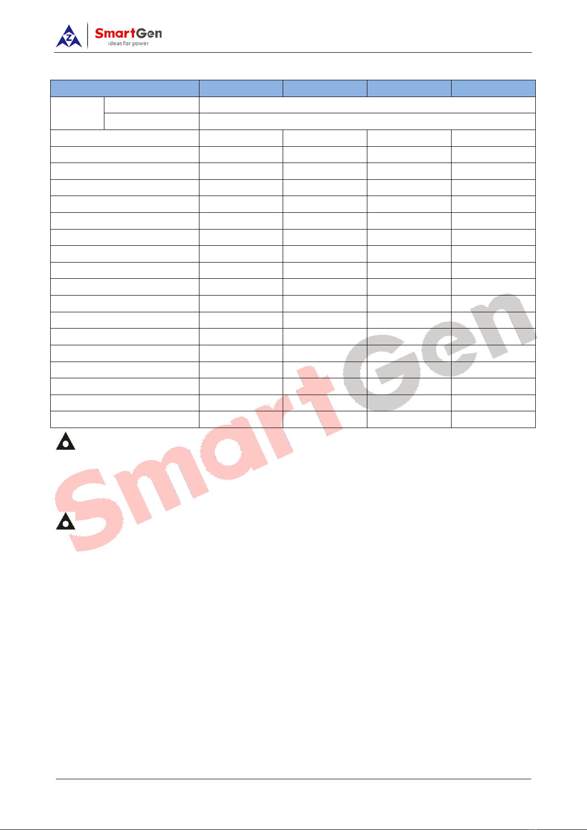
2 MODULES COMPARISON
Item HGM9510 HGM9520 HGM9530 HGM9540
LCD Dimension 4.3”
Pixel 480 x 272
AMF ●●
BUS Monitoring ●●
Parallel connection ●●●●
Digital input expansion ●●●●
Digital output expansion ●●●●
Analog input expansion ●●
Input Port 7 8 7 8
Output Port 8 8 8 8
Sensor Number 5 5 5 5
Neutral (Earth) current
Schedule function
●●●●
RS485 ●●●●
GSM
J1939 ●●●●
USB ●●●●
LINK
Real-time clock ●●●●
Event log ●●●●
NOTE:
(1) Two of the outputs are fixed: start output and fuel output.
(2)HGM9530’s analog sensors are composed by 3 fixed sensors (temperature, pressure, level) and 2
configurable sensors.
NOTE: The features of HGM9210/HGM9220/HGM9310/HGM9320/HGM9410/
HGM9420/HGM9520/HGM9610/HGM9620 controllers mentioned in this document may change, please
check the corresponding user manual for accurate information.
HGM9530 GENSET PARALLEL UNIT USER MANUAL
HGM9530 Genset Parallel Unit 2016-11-03 Version 1.4Page 10 of 65
5 OPERATION
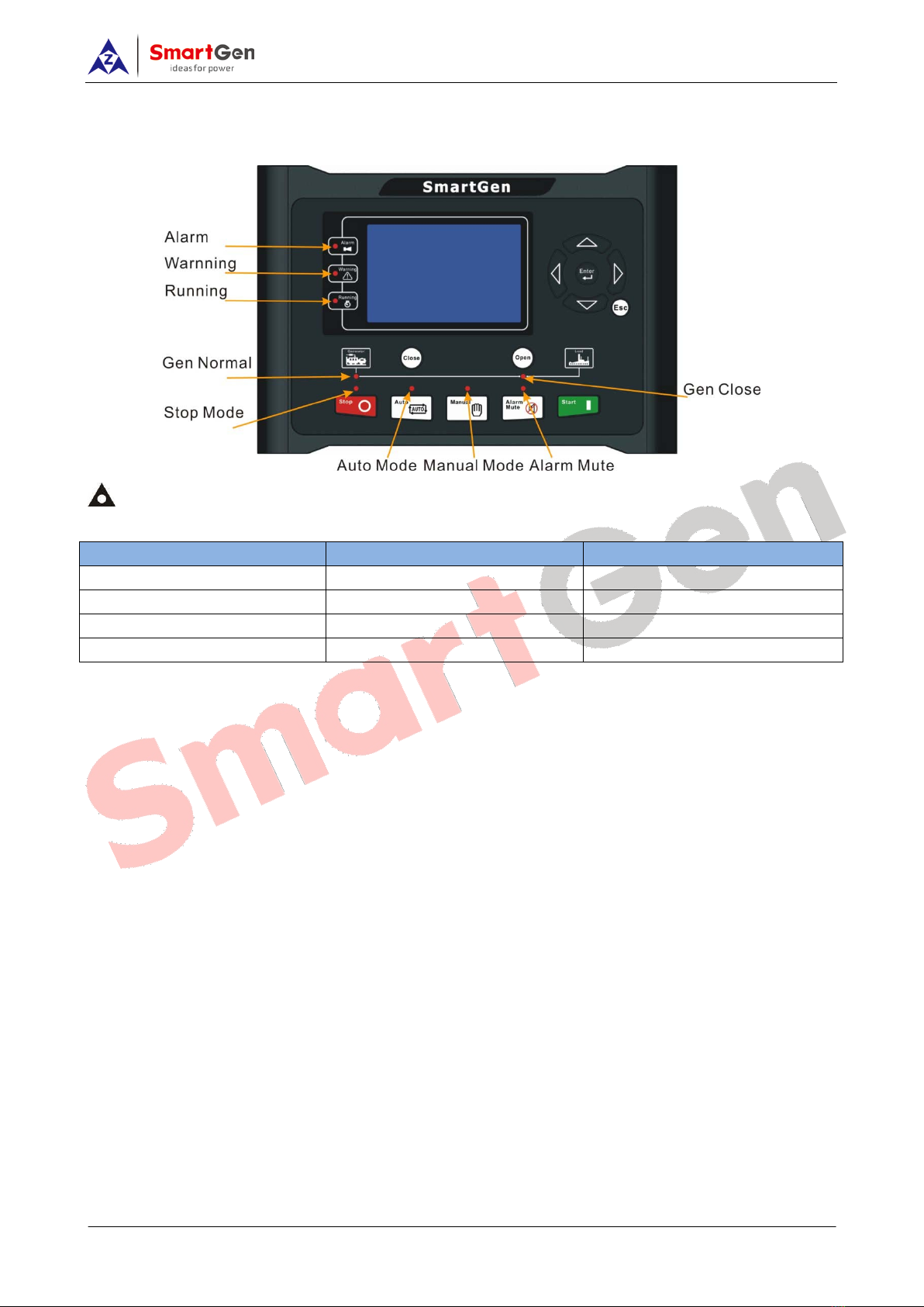
5.1 INDICATOR LIGHT
NOTE: Selected light indicators description:
Warning indicator and Alarm indicator:
Alarm Type Warning Indicator Alarm Indicator
Warning Slow flashing Slow flashing
Trip Alarm Slow flashing Slow flashing
Shutdown Alarm Off Fast flashing
Trip and Stop Alarm Off Fast flashing
Running indicator: illuminated from crank disconnect to ETS while off during other periods.
Genenerator normal light:It is light on when generator is normal; flashing when generator state is
abnormal; off when there is no generator power.

HGM9530 GENSET PARALLEL UNIT USER MANUAL
HGM9530 Genset Parallel Unit 2016-11-03 Version 1.4Page 11 of 65
5.2 PUSHBUTTONS
Icons Keys Description
Stop
Stop running generator in Auto/Manual mode; Lamp test (press
at least 3 seconds); Reset alarm in stop mode; During stopping
process, press this button again to stop generator immediately.
Start Start genset in Manual mode.
Manual Mode Press this key and controller enters in Manual mode.
Auto Mode Press this key and controller enters in Auto mode.
Mute/Reset Alarm Alarming sound off; If trip alarm occurs, pressing the button at
least 3 seconds can reset this alarm.
Close Close breaker in manual mode.
Open Open breaker in manual mode.
Up/Increase 1) Screen scroll;
2) Up cursor and increase value in setting menu.
Down/Decrease 1) Screen scroll;
2) Down cursor and decrease value in setting menu.
Left 1) Screen scroll;
2) Left move cursor in setting menu.
Right 1) Screen scroll;
2) Right move cursor in setting menu.
Set/Confirm Select viewing area.
Exit 1)Return to main menu;
2) Return to previous menu in setting menu.
NOTE: Press and simultaneously in manual mode will force generator to crank.
Successful start will not be judged according to crank disconnect conditions, operator will have to crank
the starter motor manually; when operator decides that the engine has fired, he/she should release the
button and start output will be deactivated, safety on delay will be initiated.
WARNING: Default password is 00318, user can change it in case of others change the advanced
parameters setting. Please clearly remember the password after changing. If you forget it, please
contact SmartGen services and send all information in the controller page of “ABOUT” to us.

HGM9530 GENSET PARALLEL UNIT USER MANUAL
HGM9530 Genset Parallel Unit 2016-11-03 Version 1.4Page 12 of 65
5.3 LCD DISPLAY
5.3.1 MAIN DISPLAY
Main screen show pages; use to scroll the pages and to scroll the screen.
Main Screen, including as below,
Gen: voltage, frequency, current, active power, reactive power
Bus: voltage, frequency
Engine: speed, temperature, oil pressure
Some status
Status, including as below,
Status of genset and ATS
Engine, including as below,
Engine speed, engine temperature, engine oil pressure, fuel level, flexible sensor 1, flexible sensor 2,
battery voltage, charger voltage, engine accumulated run, accumulated start times.
NOTE: If connected with J1939 engine via CANBUS port, this page also includes: coolant pressure,
coolant level, fuel temperature, fuel pressure, inlet temperature, exhaust temperature, turbo pressure,
total fuel consumption and so on. (Different engine with different parameters)
Generator, including as below,
Phase voltage, line voltage, frequency, phase sequence, current, Active Power(positive and negative),
total active power (positive and negative), Reactive Power(positive and negative), total reactive power
(positive and negative), Apparent Power, total apparent power, Power Factor(positive and negative),
average power factor (positive and negative), accumulated energy (kWh, kVarh, kVAh), multi power,
earth current, negative sequence current.
NOTE: Power factor shows as following,
Remark:
P stands for active power
Q stands for inactive power
Power
factor Conditions Active
power Reactive power
Remark
COS>0L P>0,Q>0 Input Input Load is inductive resistance.
COS>0C P>0,Q<0 Input Output Load is capacitance resistance.
COS<0L P<0,Q>0 Output Input Load is equal to one under excitation generator.
COS<0C P<0,Q<0 Output Output Load is equal to one over excitation generator.

HGM9530 GENSET PARALLEL UNIT USER MANUAL
HGM9530 Genset Parallel Unit 2016-11-03 Version 1.4Page 51 of 65
12 TYPICAL APPLICATION
HGM9530 typical application diagram
Note: Fuse F1:min. 2A; max. 20A. Fuse F2:max. 32A. Users should select suitable fuse
depend on practical application. 3 Phase 3 Wire
2 Phase 3 Wire
Single Phase 2 Wire

HGM9530 GENSET PARALLEL UNIT USER MANUAL
HGM9530 Genset Parallel Unit 2016-11-03 Version 1.4Page 52 of 65
HGM9530 Multi-genset Parallel Application
HGM9530 Single-genset Parallel Application
Note: Mains parallel function for HGM9530 controller can be selected via configurable input port.
In mains parallel mode, generator will run in parallel with mains and it will only be able to output a
fixed amount of power. (Set load mode as Gen control mode).

HGM9530 GENSET PARALLEL UNIT USER MANUAL
HGM9530 Genset Parallel Unit 2016-11-03 Version 1.4Page 53 of 65
HGM9530 Expansion Module Connection Diagram
Note: HGM9530 can be connected with multiple expansion modules via ECU CANBUS port and it
can expand 4 expansion modules most: 1 DOUT16 module, 1 DIN16 module, 2 AIN24 modules.
DOUT16 is digital output module concluding 16# auxiliary relay output.
DIN16 is digital input module concluding 16# auxiliary digital input.
AIN24 is analog input module concluding 14# K-type thermocouple input, 5# PT100 resistance input and
5# 4-20mA current input.

HGM9530 GENSET PARALLEL UNIT USER MANUAL
HGM9530 Genset Parallel Unit 2016-11-03 Version 1.4Page 54 of 65
13 POWER MANAGEMENT MODE
Power management mode can be selected via configurable input ports.
HGM9530 GENSET PARALLEL UNIT USER MANUAL
HGM9530 Genset Parallel Unit 2016-11-03 Version 1.4Page 55 of 65
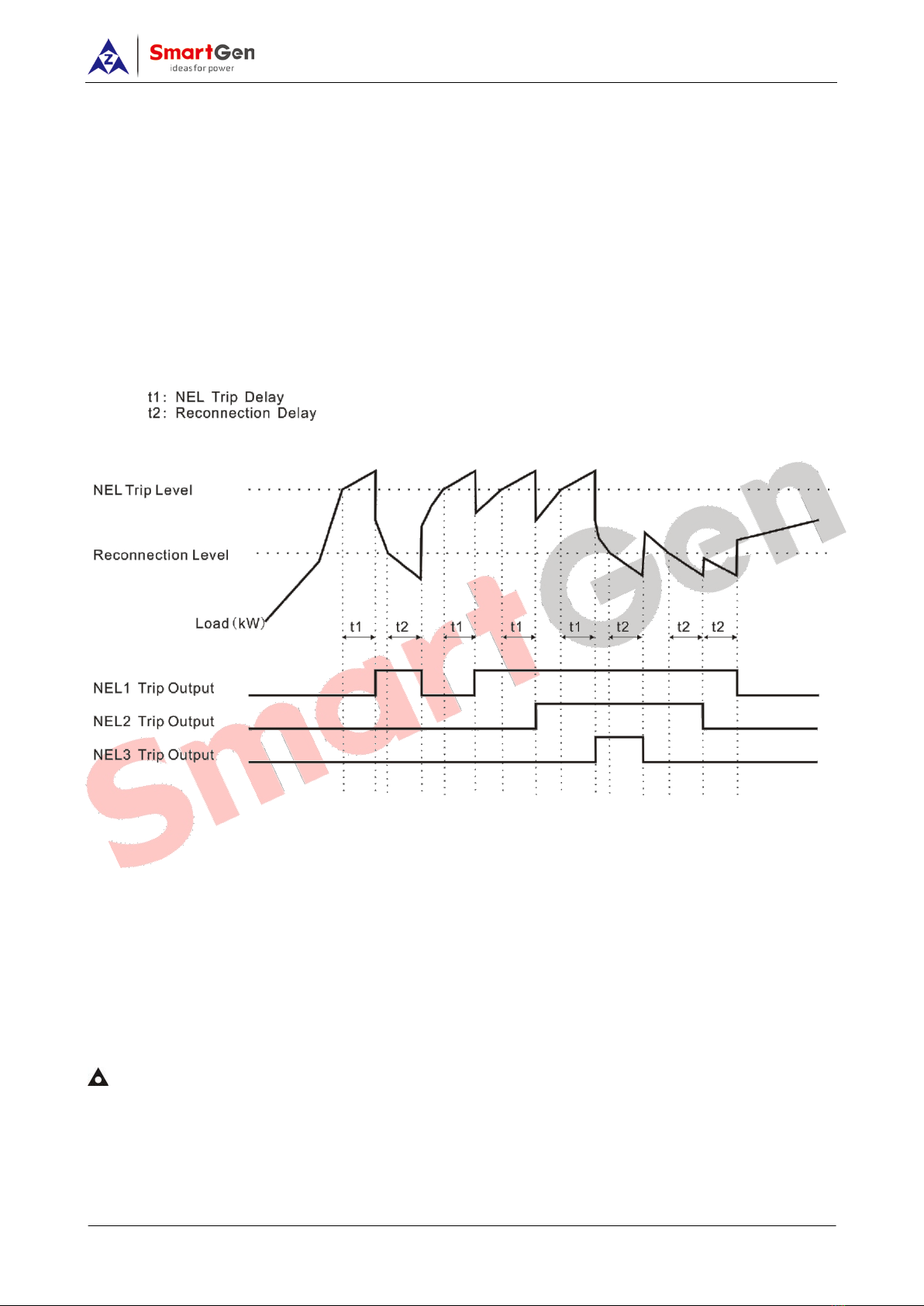
14 LOAD SHEDDING
Non-essential load ---- NEL for short.
The controller can control the NEL1, NEL2 and NEL3 to trip separately. The order of the essentiality is:
NEL3 > NEL2 > NEL1
Auto trip:
When NEL auto trip is enabled:
If the genset power has exceed the NEL trip value, after the trip delay, NEL1 will trip the earliest, and
then is NEL2,NEL3;
When NEL auto reconnection is enabled:
If the genset power has fallen below the auto reconnection set value, after the auto reconnection delay,
NEL3 will reconnection the earliest, and then is NEL2,NEL1;
Manual Trip
If NEL manual trip input is active (earthed failing edge is active), NEL1 will trip without delay; If NEL
manual trip input is active again, NEL2 will trip; If NEL manual trip input is active the third time, NEL3 will
trip. During this process, the controller do not detect if the genset power has exceed the NEL trip value or
not.
If NEL manual reconnection input is active (earthed failing edge is active), NEL3 will reconnect without
delay; If NEL manual reconnection input is active again, NEL2 will reconnect; If NEL manual
reconnection input is active the third time, NEL1 will reconnect. During this process, the controller
detects the genset power: if the genset power has fallen below the NEL reconnection value, then the
input is active; if it doesn’t, the input is deactivated.
Note: When auto trip and auto reconnection are enabled, manual trip is still active.
HGM9530 GENSET PARALLEL UNIT USER MANUAL
HGM9530 Genset Parallel Unit 2016-11-03 Version 1.4Page 56 of 65
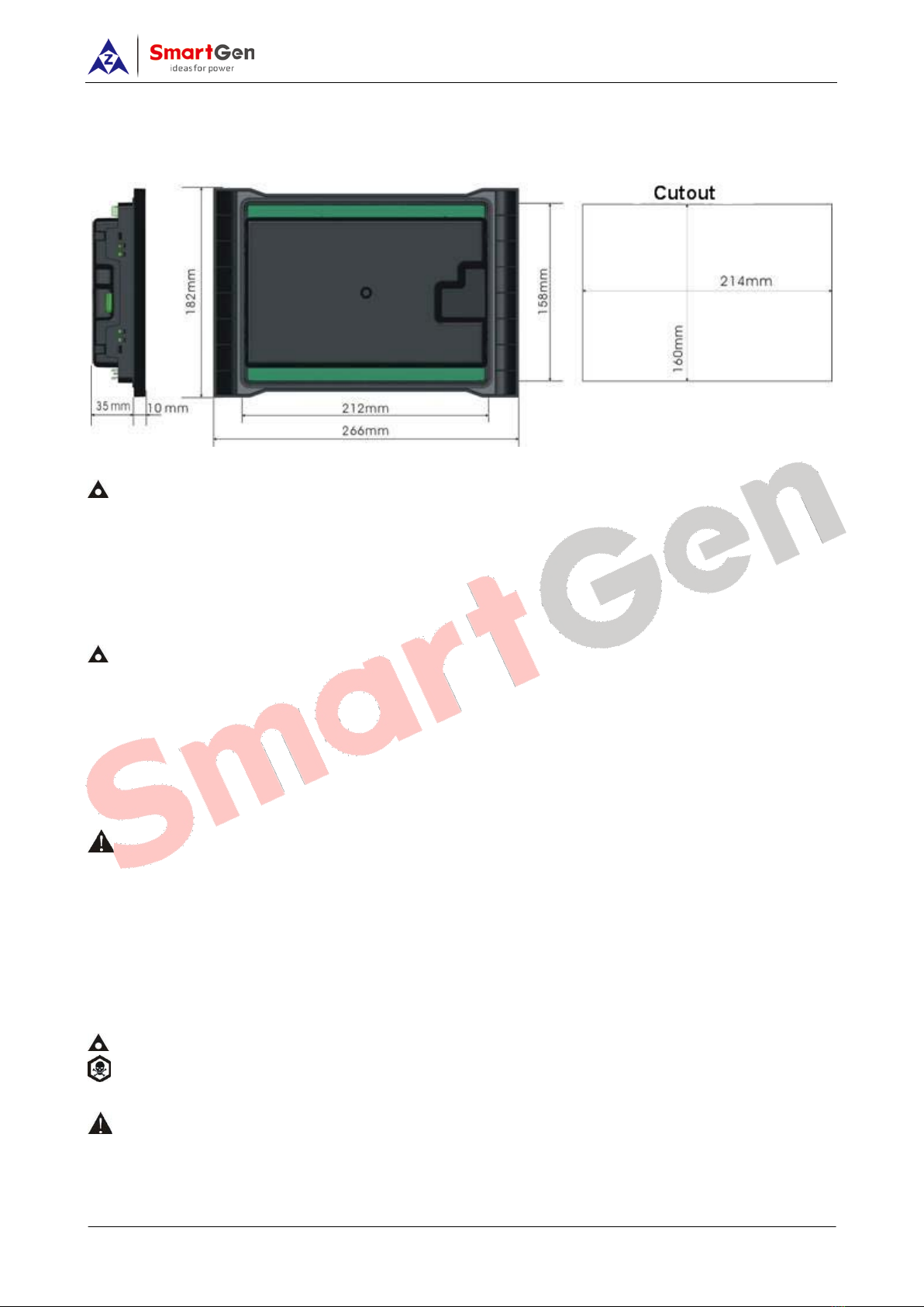
15 INSTALLATION
Controller is panel built-in design; it is fixed by clips when installed. The controller’s overall dimensions
and cutout dimensions for panel, please refers to as following,
1) Battery Voltage Input
NOTE: HGM9530 controller can suit for widely range of battery voltage (8~35) VDC. Negative of
battery must be connected with the shell of starter stable. The wire’s diameter must be over 2.5mm2 and
which is connected to B+ and B- of controller power. If floating charge configured, please firstly connect
output wires of charger to battery’s positive and negative directly, then, connect wires from battery’s
positive and negative to controller’s positive and negative input ports in order to prevent charge
disturbing the controller’s normal working.
2) Speed Sensor Input
NOTE: Speed sensor is the magnetic equipment which be installed in starter and for detecting teeth
of flywheel. Its connection wires to controller should apply for 2 cores shielding line. The shielding layer
should connect to No. 16 terminal in controller while another side is hanging in air. The else two signal
wires are connected to No.17 and No.18 terminals in controller. The output voltage of speed sensor
should be within AC(1~24)V (effective value) during the full speed. AC12V is recommended (in rated
speed). When install the speed sensor, let the sensor is spun to contacting flywheel first, then, port out
1/3 lap, and lock the nuts of sensor at last.
3) Output And Expand Relays
CAUTION: All outputs of controller are relay contact output type. If need to expand the relays, please
add freewheel diode to both ends of expand relay’s coils (when coils of relay has DC current) or,
increase resistance-capacitance return circuit (when coils of relay has AC current), in order to prevent
disturbance to controller or others equipment.
4) AC Input
Current input of controller must be connected to outside current transformer. And the current
transformer’s secondary side current must be 5A. At the same time, the phases of current transformer
and input voltage must correct. Otherwise, the current of collecting and active power maybe not correct.
NOTE: ICOM port must be connected to negative pole of battery.
WARNING! When there is load current, transformer’s secondary side prohibit open circuit.
5) Withstand Voltage Test
CAUTION! When controller had been installed in control panel, if need the high voltage test, please
disconnect controller’s all terminal connections, in order to prevent high voltage into controller and
damage it.
Table of contents
Other Smartgen Industrial Equipment manuals


