Curved Onyx by Draper Page 2 of 3
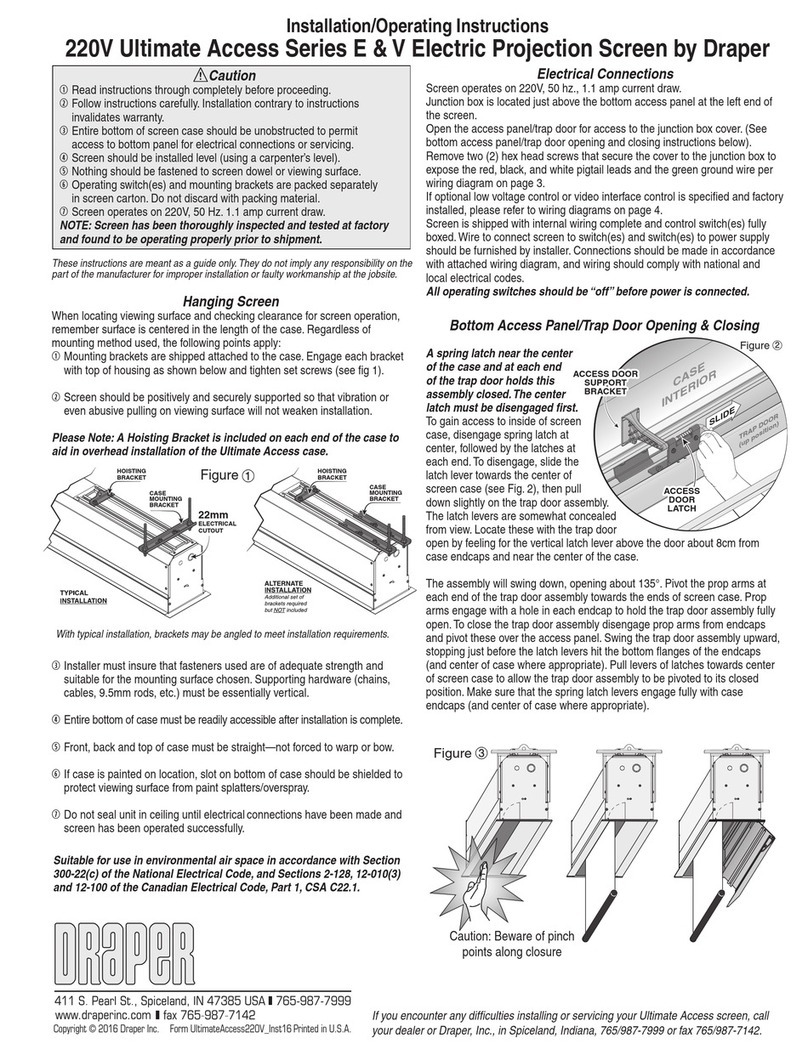
Figure 8
Mounting Screen to Wall
1Determine height at which screen is to be mounted.
Please Note: Top edge of screen frame will be located 1.5"above mounting
bracket hole centerline when mounted to wall.
2Mark hole centerline so that brackets can be mounted parallel and at equal
height.
3Install brackets so that the outermost edges are safely within the overall
length of the aluminum frame extrusion to allow for minor horizontal screen
adjustments. Installer is responsible for providing attachment hardware.
4The bottom center bracket on the Curved Onyx acts as a locking bracket.
Slide the center plate up, then push the screen back against the wall,
releasing the center plate. The tongue on the center plate will then slide
down into the frame extrusion, locking the frame in place.
5Position screen slightly above brackets on wall.
Surface to Frame Assembly
1Return frame onto clean surface, face down, and drape completed surface
assembly over completed frame profile with rounded edges of surface
retention extrusions visible.
2Hook surface retention extrusions on any side of surface to notch #2 on
corresponding side of frame extrusion (see Fig. 8).
Figure 10
6Lower screen until it engages over brackets. Center screen horizontally
on brackets as necessary.
Please Note: Make sure screen is installed level.
Figure 6
Surface Preparation
1Move frame assembly out of the way, unroll viewing surface and place on
smooth/clean surface. (Orient viewing surface so that folded side of hem is
visible.)
2Insert plastic tubing inside pocket formed by hem on all 4 edges of viewing
surface (see Fig. 6).
3Divide surface retention extrusions up so they will be evenly spaced all the
way around the screen.
4Carefully slide surface retention extrusions (rounded edge visible) along
hem and onto surface on all 4 edges of fabric (see Fig. 7). Caution: Do
not allow fabric to snag on ends of extrusions. If the screen
fabric is not parallel with the surface retention extrusion, then
it may slit and tear during installation.
Figure 7
Plastic Tubing
Surface Retention
Extrusion
Back of
Viewing Surface
Surface
Retention
Extrusion
Fabric Attachment Extrusions
Viewing
Surface
Notch #1
Notch #2
Notch #3
.draperinc.com (765) 987-799
Corner Reinforcement Kit (Part No. 253696)
1If screen is being flown (suspended), or is 120" (viewing area) or larger in
height or width, install Corner reinforcement Gussets to all four corners
(see Fig. 9)
Figure 9
Onyx Brackets
Outer Brackets Center Brackets
To p
Bottom
(locking)
C264.049SA
C501.324
C501.325
C501.326
Please Note: To make this step easier, pinch the end of the pocket closed
before sliding it into the surface retention extrusions.
5The top and bottom of the screen should have the ssame number of
surface retention extrusions. The two sides should also have the same
number. This will allow even spacing all the way around the screen.
.6Verify that all surface retention extrusions are installed with rounded edge
visible and are centered on surface material.
3Repeat on opposite side of surface, again using notch #2.
4Repeat steps 2-3 with remaining edges of surface.
5Ensure surface retention extrusions are centered lengthwise in tension
slots on all 4 edges of surface.
6If additional tension in certain areas of the screen is desired, adjust surface
retention extrusions to notch #1 or #3 as necessary.
Please Note: It is not necessary to adjust more than one edge at a time to
increase surface tension.
