manuals.online logo
Brands
  1. Home
  2. •
  3. Brands
  4. •
  5. dreambaby
  6. •
  7. Baby Accessories
  8. •
  9. dreambaby Nottingham Gro-Gate L891 User manual

dreambaby Nottingham Gro-Gate L891 User manual

1
Nottingham Gro-Gate®
L891
L2065
For customers in US only:
Do Not Return to Store, if you have any
questions, please call us on
Tel: (336) 454-5716, (888) 271-6959 Toll
free or email us at [email protected]
INSTRUCTIONS: Dual Fix - Wall Mounted Gate or Pressure Fit Barrier
Important: Keep instructions for future reference. Read INSTRUCTIONS thoroughly before assembling and installing gate.
Complies with Standards: ASTM F1004-15a
INSTRUCCIONES: Barrera con sujeción por fijación a la pared o barrera ajustada a presión
Importante: Conserve estas instrucciones para futura referencia. Lea las INSTRUCCIONES totalmente antes de ensamblar e instalar la compuerta.
Cumple con las Normas: ASTM F1004-15a
Page 2 WALL-MOUNTED GATE INSTALLATION
Página 2 BARRERA DE MONTAJE CON FIJACIÓN A LA PARED
Page 4 PRESSURE BARRIER INSTALLATION
Página 4 BARRERA DE MONTAJE A PRESIÓN
Fits openings 27.5 - 41inch/69.5 - 104cm.
To prevent serious injury or death, securely install gate and use according to
manufacturer’s instructions.
This product is intended for use with children 6 - 24 months.
Never leave child unattended. This product may not prevent all accidents.
This product is not to be used with a child able to climb over or dislodge/open the
gate.
The surfaces that the safety gate is to be xed to must be suitable for the purpose and
must be structurally sound. NOTE: Do not use this gate if it can’t be installed to walls,
door frames or posts – tightly and atly.
This safety gate shall not be tted across window openings and the like.
Securely install and operate the gate according to instructions to help prevent
accidental injury.
Do not use the safety gate if any components are damaged or missing. Install this
gate away from heaters and other sources of heat.
This gate is intended for indoor use and is not to be exposed to outdoor elements.
Gate is not meant to replace proper adult supervision.
If the gate is used at the bottom of the stairs to prevent the child from climbing up the
stairs, it must be placed on the lowest stair.
If the gate is to be used at the top of the stairs to prevent the child from falling down
the stairs, it must not be placed on any stair below the level of the top stair.
Adult Assembly Required. Hardware contains small screws with sharp points and
small parts that can present a choking hazard. Keep unassembled parts out of reach
of small children.
Always install with mounting cups with screws when gate is used at top of stairs.
The use of mounting cups is recommended at all times.
WARNING The position of the safety barrier in relation to the
stairs may have an adverse effect on your child’s safety.
WARNING
•
•
•
•
•
•
•
•
•
•
•
•
•
•
•
•
Se ajusta a aberturas 27.5 - 41inch/69.5 - 104cm.
Para prevenir lesiones graves o muerte, instale la compuerta bien segura y úsela de
acuerdo a las instrucciones del fabricante.
Este producto está destinado a uso con niños 6 - 24 meses.
Nunca deje al niño desatendido. Este producto podría no prevenir todos los accidentes.
Nunca use esta compuerta con un niño que es capaz de desalójelo/abrirla o trepar por
encima.
La supercie en que se jará la compuerta de seguridad debe ser adecuada para
ese n y ser estructuralmente sólida. NOTA: No use esta compuerta si no se la puede
instalar en paredes, marcos de puertas o postes bien aseguradas y planas.
Esta compuerta de seguridad no se debe instalar en aberturas de ventanas o similares.
Instale la compuerta bien segura y úsela de acuerdo a las instrucciones para evitar
lesiones accidentales.
No use la compuerta de seguridad si falta o está dañado cualquier componente.
Instale la compuerta de seguridad alejada de estufas u otras fuentes de calor.
Esta compuerta está destinada a uso en interiores y no se la debe exponer a los
elementos al aire libre.
La compuerta no pretende reemplazar la supervisión adecuada de un adulto.
Si se usa la compuerta al pie de la escalera para impedir que el niño suba la escalera,
debe estar colocada en el escalón más bajo.
Si la compuerta es para usarla en la parte de arriba de la escalera para impedir que
el niño se caiga escalera abajo, no debe ser colocada en un escalón bajo el nivel del
escalón superior.
El montaje debe de ser realizado por un adulto. Las piezas para el montaje contienen
pequeños tornillos que pueden presentar riesgo de asxia. Mantenga las piezas sin
montar fuera del alcance de los niños.
El uso de tazas de montaje se recomienda en todo momento.
Montar las tazas de montaje al utilizar la puerta en la parte superior de las escaleras.
ADVERTENCIA La posición de la barrera de seguridad con
relación a las escaleras puede tener un efecto adverso sobre la seguridad
de su niño.
ADVERTENCIA
•
•
•
•
•
•
•
•
•
•
•
•
•
•
27.5 - 41 Inch
69.5 - 104 cm
28 Inch
71 cm
27.5 - 41 Inch
69.5 - 104 cm
28 Inch
71 cm

2
1
X = 69.5 73.5 cm
X = 73.5 78.5 cm
X = 78.5 83.5 cm
X = 83.5 88.5 cm
X = 88.5 93.5 cm
X
A
B
C
D
E
1
+
+
+
+
+
1
1
1
1
H
H
H
H
H
8
+
+
+
+
+
7
6
5
4
X = 93.5 98.5 cm
X = 98.5 104 cm
X = 27.5 29 Inch
X = 29 31 Inch
X = 31 33 Inch
X = 33 35 Inch
X = 35 37 Inch
X = 37 39 Inch
X = 39 41 Inch
F
G
+
+
1
1
H
H
+
+
3
2
1
Step 1
Measure the width of the opening of where you intend to install the gate.
Mida el ancho de la abertura donde piensa instalar la compuerta.
Step 2
Adjust the two gate sections to one of the 7 positions shown, according to
the size of the opening you intend to fit the gate in. Align the holes on both
gate sections. Secure the gate by fastening the screw (B) into the screw (A)
as shown in the diagram. Do not attempt to fasten the gate using less than
4 screws. Make sure that the flat surfaces of the two gates are facing each
other.
Ajuste las dos secciones de la puerta en una de las 7 posiciones que se
muestran, de acuerdo al tamaño de la abertura en donde desea colocar
la puerta. Alinee los agujeros en ambas secciones de la puerta. Asegure
la puerta ajustando el tornillo (B) en el tornillo (A), como se muestra en
el diagrama. No intente ajustar la puerta utilizando menos de 4 tornillos.
Asegúrese de que las superficies lisas de las dos puertas se enfrentan entre
si.
2
!
4
A
1 2 3 4 5 6 7 8
B C D E F G H
B
B
BA
A
A
27.5 - 41 Inch
69.5 - 104 cm
28 Inch
71 cm

4
A4
B2
C2
D2
E2
F2
G2
H7
K1
L2
M
6
J
2
I
4x25 mm 4x55 mm
WARNING! The use of mounting cups is recommended at all times. If the gate is used at
the bottom of the stairs to prevent the child from climbing up the stairs, it must be placed
at the front of the lowest tread possible.
¡ADVERTENCIA! El uso de tazas de montaje se recomienda en todo momento. Si se usa
la compuerta al pie de la escalera para impedir que el niño suba la escalera, debe estar
colocada en el escalón más bajo.
Floor
Piso

Landing • Descansillo

WARNING! The use of mounting cups is recommended at all times. Always install with mounting cups with
screws when gate is used at top of stairs. If the gate is to be used at the top of the stairs to prevent the child from
falling down the stairs, it must not be placed on any stair below the level of the top stair.
¡ADVERTENCIA! El uso de tazas de montaje se recomienda en todo momento. Montar las tazas de montaje al
utilizar la puerta en la parte superior de las escaleras. Si la compuerta es para usarla en la parte de arriba de la
escalera para impedir que el niño se caiga escalera abajo, no debe ser colocada en un escalón bajo el nivel del
escalón superior.
Step 3
Place the gate perpendicular to the door opening and the floor (3A). (3B) Mark the
position for the wall fittings (C) on the wall surfaces, opposite where you want the gate
to hinge from. Install the wall fittings (C) using the appropriate fixings depending on the
surface available (double-sided adhesive pads or screw with plugs): wood screws for
wooden surfaces, multi-use dowel and concrete screws for concrete surfaces, multi-
use dowel and cement screws for cement surfaces, metal screws for metal surfaces.
Double-sided adhesive pads (H) and wood screws (J) are provided.
Coloque la puerta de seguridad de manera perpendicular a la puerta y al suelo(3A).
(3B) Marque la posición para los fijadores de pared (C) en la superficie de la pared
opuesta a donde quiere la bisagra de la puerta. Asegure los fijadores de pared (C)
utilizando los fijadores apropiados dependiendo de la superficie disponible(Parches
adesivos de doble cara o tornillos con fijacion): tornillos para madera para superficies
de madera, clavijas multi uso y tornillos para concreto para superficies de concreto,
clavijas multiuso y tornillos para cemento para superficies de cemento, tornillos de
metal para superficies de metal. Se proporcionan almohadillas adhesivas de doble
cara (H) y tornillos para madera (J).
1.5 Inch
37 mm
27.2 Inch
692 mm
Wall • Pared
Floor • Piso
Top view of gate
Vista superior de la compuerta
Side view of gate
Vista lateral de la compuerta
2
2
+
Ensure that the surface you are mounting the gate is structurally
sound such as solid timber, brick or masonry. For plaster/gyprock
surface, locate the timber beam or stud behind and mount in this
location (mounting on plaster/gyprock alone is not strong enough and
not safe). Do not mount on glass.
Asegúrese de que la superficie se va a montar la puerta está en
buenas condiciones estructurales , tales como madera sólida ,
ladrillo o mampostería . Para superficie de yeso / gyprock , localizar
la viga de madera o viga detrás y montar en esta ubicación ( montaje
sobre revoque / gyprock por sí sola no es lo suficientemente fuerte y
no es seguro ) . No monte sobre el vidrio.
3A 3B
J
K
C
3
Step 5
Screw the two short screw adjusters (D) into the holes on the latch side of the gate. Position the round nut
(I) into the side holes on the hinge side of the gate. Insert the hinge spindles (E) into the gate and screw
them into the round nut (I).
Atornille los dos pequeños tornillos de ajuste (D) en los agujeros del cerrojo a ambos lados de la puerta.
Coloque la tuerca redonda (I) en los orificios laterales en el lado de la bisagra de la puerta. Inserte los dos
ejes de las bisagras (E) en la puerta y atorníllelos en la tuerca redonda (I).
5
22
D
I E
Step 6
Place the gate into the desired opening making sure to insert both hinge spindles (E) into the hinges (F).
Continue to adjust the screw adjusters (D) until the head of the screw adjuster touches the mounting cups
surface. Make sure that distance between the wall and the latch side of the frame is no less than 0.9 Inch
/ 22 mm and no more than 2 Inch / 52 mm, and the distance between the wall and the other side of the
frame is no less than 0.9 Inch / 24 mm and no more than 2.9 Inch / 73 mm.
Ubique la puerta en la abertura deseada asegurándose de insertar los dos ejes de las bisagras (E) en las
bisagras (F). Continúe ajustando los tornillos (D) hasta que los tornillos tocan la surface de los fixations
murales. Asegúrese de que la distancia entre la pared y el lado del pestillo del marco no es menor a 0.9
Inch / 22 mm ni mayor a 2 Inch / 52 mm, y que la distancia entre la pared y el otro lado del marco no es
menor a 0.9 Inch / 24 mm ni mayor a 2.9 Inch / 73 mm.
max 2 inch
min 0.9 inch
max 52 mm
min 22 mm
max 2.9 inch
min 0.9 inch
max 73 mm
min 24 mm
!
6
D
EF
Step 7
Unlock the gate by sliding the latch towards the wall (1) and then lifting the latch (2) this
will retract the screw adjusters (D).
Desbloquear la puerta deslizando el pestillo hacia la pared (1) y luego levantando el
pestillo (2), esto replegará los ajustadores de los tornillos (D).
7
2
12.5mm
0.1 inch
8
Step 8
Remove the gate from the opening and on the panel opposite to the latch panel winde out both spindles (E) 0.1 Inch / 2.5
mm to apply pressure to the gate.
Retire la puerta de la abertura y en el panel opuesto al mango, desenroscar los dos ejes de las bisagras (E) de 0.1 Inch /
2.5 mm para aplicar presión a la puerta.
E
click
10
Step 10
Push the latch downwards gently. The screw adjusters
(D) will extend and the latch should ‘click’ into place
indicating that the gate is secure. Place the hinge-covers
(G) on the hinges (F). These can later be removed using
a screwdriver.
Mueva cuidadosamente el pestillo. Los ajustadores del
tornillo (D) se extenderán y el cerrojo debería hacer un
„click“ indicando que la puerta está asegurada. Coloque
los cobertores de las bisagras (G) en las bisagras (F).
Estos pueden ser removidos posteriormente utilizando un
destornillador.
G
F
9
Step 9
Place the gate into
the desired opening
making sure to insert
both hinge spindles (E)
into the hinges (F).
Ubique la puerta en
la abertura deseada
asegurándose de
insertar los dos ejes de
las bisagras (E) en las
bisagras (F).
FE
Step 4
Mark the position for the hinges (F) on the opposite wall surface to the wall fittings. The top hole for
the lower wall fixing should be 1.6 Inch / 39 mm from the floor. The top hole for the upper wall fixing
should be 27.3 Inch / 694 mm from the floor. Fix the hinges (F) using the appropriate fixings depending
on the surface available: wood screws (J) for wooden surfaces, multi-use dowel and concrete screws
for concrete surfaces, multi-use dowel and cement screws for cement surfaces, metal screws for metal
surfaces. Wood screws (J) are provided.
*If there is a skirting board (baseboard) see page 6
Marque la posición para las bisagras (F), en la superficie de la pared opuesta a los fijadores de la pared. El
agujero superior para la bisagra inferior debería estar a 1.6 Inch / 39 mm del suelo. El agujero superior para
la bisagra superior, debería estar a 27.3 Inch / 694 mm del suelo. Asegure las bisagras (F) utilizando los
fijadores apropiados dependiendo de la superficie disponible: tornillos para madera (J) para superficies
de madera, clavijas multi uso y tornillos para concreto para superficies de concreto, clavijas multiuso
y tornillos para cemento para superficies de cemento, tornillos de metal para superficies de metal. Se
proporcionan tornillos para madera (J).
*Se existir rodapé consulte la página 6
1.6 Inch
39 mm
27.3 Inch
694 mm
4
+
2
F
J
K
4
C
4
PRESSURE INSTALLATION 
4
A4
B4
C2
D4
F
4
E2
G2
H1
L
7
K2
M
2
I
4x25 mm 4x55 mm
Step 3
Screw the two short screw adjusters (D) into the holes on the latch side of the gate.
Position the round nut (I) into the side holes on the hinge side of the gate. Insert the
two long screw adjusters (G) into the gate and screw them into the round nut (I).
Atornille los dos pequeños tornillos de ajuste (D) en los agujeros del cerrojo a ambos
lados de la puerta. Coloque la tuerca redonda (I) en los orificios laterales en el lado de
la bisagra de la puerta. Insertelos los dos grandes tornillos de ajuste (G) en la puerta
y atorníllelos en la tuerca redonda (I).
3
2
2
DG
I
1
X = 69.5 73.5 cm
X = 73.5 78.5 cm
X = 78.5 83.5 cm
X = 83.5 88.5 cm
X = 88.5 93.5 cm
X
A
B
C
D
E
1
+
+
+
+
+
1
1
1
1
H
H
H
H
H
8
+
+
+
+
+
7
6
5
4
X = 93.5 98.5 cm
X = 98.5 104 cm
X = 27.5 29 Inch
X = 29 31 Inch
X = 31 33 Inch
X = 33 35 Inch
X = 35 37 Inch
X = 37 39 Inch
X = 39 41 Inch
F
G
+
+
1
1
H
H
+
+
3
2
1
Step 1
Measure the width of the opening of where you intend to install the gate.
Mida el ancho de la abertura donde piensa instalar la compuerta.
Step 2
Adjust the two gate sections to one of the 7 positions shown, according to the size of
the opening you intend to fit the gate in. Align the holes on both gate sections. Secure
the gate by fastening the screw (B) into the screw (A) as shown in the diagram.
Do not attempt to fasten the gate using less than 4 screws. Make sure that the flat
surfaces of the two gates are facing each other.
Ajuste las dos secciones de la puerta en una de las 7 posiciones que se muestran,
de acuerdo al tamaño de la abertura en donde desea colocar la puerta. Alinee los
agujeros en ambas secciones de la puerta. Asegure la puerta ajustando el tornillo
(B) en el tornillo (A), como se muestra en el diagrama. No intente ajustar la puerta
utilizando menos de 4 tornillos. Asegúrese de que las superficies lisas de las dos
puertas se enfrentan entre si.
2
!
4
A
1 2 3 4 5 6 7 8
B C D E F G H
B
B
BA
A
A
27.5 - 41 Inch
69.5 - 104 cm
28 Inch
71 cm
Ensure that the surface you are mounting the gate is structurally sound such
as solid timber, brick or masonry. For plaster/gyprock surface, locate the
timber beam or stud behind and mount in this location (mounting on plaster/
gyprock alone is not strong enough and not safe). Do not mount on glass.
Asegúrese de que la superficie se va a montar la puerta está en buenas
condiciones estructurales , tales como madera sólida , ladrillo o mampostería
. Para superficie de yeso / gyprock , localizar la viga de madera o viga detrás
y montar en esta ubicación ( montaje sobre revoque / gyprock por sí sola no
es lo suficientemente fuerte y no es seguro ) . No monte sobre el vidrio.
WARNING! The use of mounting cups is recommended at all times. If the gate is used at
the bottom of the stairs to prevent the child from climbing up the stairs, it must be placed
at the front of the lowest tread possible.
¡ADVERTENCIA! El uso de tazas de montaje se recomienda en todo momento. Si se usa
la compuerta al pie de la escalera para impedir que el niño suba la escalera, debe estar
colocada en el escalón más bajo.
Floor
Piso

Landing • Descansillo

WARNING! The use of mounting cups is recommended at all times. Always install with mounting cups with
screws when gate is used at top of stairs. If the gate is to be used at the top of the stairs to prevent the child from
falling down the stairs, it must not be placed on any stair below the level of the top stair.
¡ADVERTENCIA! El uso de tazas de montaje se recomienda en todo momento. Montar las tazas de montaje al
utilizar la puerta en la parte superior de las escaleras. Si la compuerta es para usarla en la parte de arriba de la
escalera para impedir que el niño se caiga escalera abajo, no debe ser colocada en un escalón bajo el nivel del
escalón superior.
5
Step 5
Place the gate into the desired opening. Continue to adjust the screw adjusters (D)(G) until the head of the
screw adjuster touches the mounting cups (C) surface. Make sure that distance between the wall and the
latch side of the frame is no less than 0.9 Inch / 22 mm and no more than 2 Inch / 52 mm, and the distance
between the wall and the other side of the frame is no less than 0.9 Inch / 24 mm and no more than 2.9 Inch
/ 73 mm.
Ubique la puerta en la abertura deseada. Continúe ajustando los tornillos (D)(G) hasta que los tornillos tocan
la surface de los fixations murales (C). Asegúrese de que la distancia entre la pared y el lado del pestillo del
marco no es menor a 0.9 Inch / 22 mm ni mayor a 2 Inch / 52 mm, y que la distancia entre la pared y el otro
lado del marco no es menor a 0.9 Inch / 24 mm ni mayor a 2.9 Inch / 73 mm.
max 2 inch
min 0.9 inch
max 52 mm
min 22 mm
max 2.9 inch
min 0.9 inch
max 73 mm
min 24 mm
!
5
C
D
G
C
7
8 9
Step 6
Unlock the gate by sliding the latch towards the wall (1) and then lifting the latch (2) this will retract the
screw adjusters (D).
Desbloquear la puerta deslizando el pestillo hacia la pared (1) y luego levantando el pestillo (2), esto
replegará los ajustadores de los tornillos (D).
62
1
2.5mm
0.1 inch
Step 7
Remove the gate from the opening and on the panel opposite to the
latch panel wind out both screw adjuster (G) 0.1 Inch / 2.5 mm to apply
pressure to the gate.
Retire la puerta de la abertura y en el panel opuesto al mango, desenroscar
los dos tornillos del ajuste (G) de 0.1 Inch / 2.5 mm para aplicar presión a
la puerta.
G
Step 8
Place the gate into the
desired opening.
Ubique la puerta en la
abertura deseada.
clac
Step 9
Push the latch downwards gently. The screw
adjusters (D) will extend and the latch should ‘click’
into place indicating that the gate is secure.
Mueva cuidadosamente el pestillo. Los ajustadores
del tornillo (D) se extenderán y el cerrojo debería
hacer un „click“ indicando que la puerta está
asegurada.
Step 4
Place the gate perpendicular to the door opening and the floor (4A). (4B) Mark
the position for the wall fittings (C) on the wall surfaces. Install the wall fittings
(C) using the appropriate fixings depending on the surface available (double-
sided adhesive pads or screw with plugs): wood screws for wooden surfaces,
multi-use dowel and concrete screws for concrete surfaces, multi-use dowel and
cement screws for cement surfaces, metal screws for metal surfaces. Double-
sided adhesive pads (E) and wood screws (F) are provided.
*If there is a skirting board
(baseboard) see page 6
Coloque la puerta de seguridad de manera perpendicular a la puerta y al
suelo(4A).(4B) Marcar la posición de las fijaciones de pared (C). Asegure los
fijadores de pared (C) utilizando los fijadores apropiados dependiendo de la
superficie disponible(Parches adesivos de doble cara o tornillos con fijacion):
tornillos para madera para superficies de madera, clavijas multi uso y tornillos
para concreto para superficies de concreto, clavijas multiuso y tornillos para
cemento para superficies de cemento, tornillos de metal para superficies de
metal. Se proporcionan almohadillas adhesivas de doble cara (E) y tornillos para
madera (F).
*En présence de plinthes au mur voir page 6
1.5 Inch
37 mm
27.2 Inch
692 mm
4
4
+
4A
Wall • Pared
Floor • Piso
Top view of gate
Vista superior de la compuerta
Side view of gate
Vista lateral de la compuerta
F
K
C
4B
6
MAINTENANCE & CARE • MANTENIMIENTO Y CUIDADO
Gate must be tted according to instructions, to ensure it works correctly.
Regularly check gate to ensure it is tted properly and securely. Adjust as required.
Regularly check tension knobs and rubber pads to make sure the gate is securely in place.
Do not use the safety gate if any components are damaged or missing.
To clean, wipe surface with a damp cloth or sponge using mild detergent and warm water.
Never clean with abrasive, ammonia based bleach based or spirit type cleaners.
If vthe gate does not stay in position or does not swing closed properly, the gate may not be installed
properly.
Remove and re-install gate, make sure the gate is installed vertically.
Any additional and replacement parts should be obtained from
Tee-Zed Products. Only use original Dreambaby® spare parts for this product.
Se debe ajustar la compuerta según las instrucciones, para asegurar que funcione correctamente.
Revise periódicamente la compuerta para asegurarse de que esté ajustada correcta y rmemente. Ajuste si es
necesario.
Periódicamente revise las perillas de tensión y almohadillas de goma para asegurarse de que la compuerta esté
segura en su lugar.
No use la compuerta de seguridad si algún componente falta o está dañado.
Para limpiar, pase un paño o esponja húmedos sobre la supercie, usando un detergente suave y agua tibia.
No use nunca limpiadores abrasivos a base de amoníaco o alcohol desnaturalizado.
Si la compuerta no se mantiene en posición ono cierra correctamente,puede ser que no esté instaladacorrectamente.
Sáquela y vuelva a instalarla, asegurándose de que la compuerta quede vertical.
       
piezas de repuesto Dreambaby® para este producto.
•
•
•
•
•
•
•
•
•
•
•
•
•
•
•
•
•
•
youtube.com/dreambabytv
facebook.com/dreambabysafety
twitter.com/dreambabysafety
TEE-ZED PRODUCTS, LLC ACCEPTS NO RESPONSIBILITY FOR ANY LOSS OR DAMAGE SUFFERED BY ANY PERSON AS A RESULT OF
THE USE OR MISUSE OF THESE GOODS. IN THE CASE OF ANY DEFECT IN THE GOODS, TEE-ZED’S LIABILITY SHALL BE LIMITED
SOLELY TO REPLACEMENT OF THE DEFECTIVE GOODS.
TEE-ZED PRODUCTS, LLC NO SE HACE RESPONSABLE DE NINGUNA PÉRDIDA O DAÑO SUFRIDO POR ALGUNA PERSONA COMO
RESULTADO DEL USO O DE LA MALA UTILIZACIÓN DE ESTAS MERCANCÍAS. EN CASO DE CUALQUIER DEFECTO EN LAS MERCANCÍAS,
LA RESPONSABILIDAD DE TEE-ZED’S SERÁ LIMITADA ÚNICAMENTE AL REEMPLAZO DE LAS MERCANCÍAS DEFECTUOSAS.
Tee-Zed Products Pty Ltd
PO Box 2022,
Bondi Junction NSW 1355
AUSTRALIA Tel: +61 (0)2 9386 4000
info@tee-zed.com.au
www.dreambaby.com.au
Tee-Zed Products, LLC
PO Box 1662,
Jamestown, NC 27282
USA Tel: 336-454-5716,
Toll free: 1-888-271-6959
www.dream-baby.com
Dreambaby
®
products by
Los productos Dreambaby
®
por
Made in Vietnam.
Hecho en Vietnam.
©2016 Tee-Zed Products, LLC
X
!
If there is a skirting board (baseboard) to which the Nottingham gate is to be attached, always measure the
width of the opening on the floor between the 2 skirting boards (baseboards) and adjust the two gate sections
to one of the five positions shown in figure 2. If the screw adjusters (D) on the top of the gate are too short,
firstly mount the Spacer (L) on the handle side at the top of the gate to the wall using the appropriate fixings
depending on the surface available (double-sided adhesive pads or 2 screw 4x55mm (M) with plug) and then
screw the wall fitting (C) on it. Adjust the screw adjuster (D) on the handle side. Make sure that the gate is
mounted firmly and evenly in vertical position.
Si hay un zócalo (rodapié) a la que la puerta de Nottingham está unida, se tiene que medir siempre la anchura
de la abertura en el suelo entre los 2 zócalos y ajustar las dos secciones de la puerta a una de las cinco
posiciones mostradas en la figura 2. Si los ajustadores de tornillo (D) en la parte superior de la puerta son
muy cortos, en primer lugar montar el espaciador (L) en el lado de la manivela en la parte superior de la
puerta a la pared, usando las fijaciones adecuadas en función de la superficie disponible (adhesivo de doble
cara o 2 tornillos 4x55mm (M) con enchufe); después, atornilla el conector (C) en la pared. Ajuste el tornillo
de ajuste (D) en el lado de la manivela. Asegúrese de que la puerta está montada firmemente y en posición
vertical.
L
M2x
 

Other manuals for Nottingham Gro-Gate L891

1

This manual suits for next models

1

Other dreambaby Baby Accessories manuals

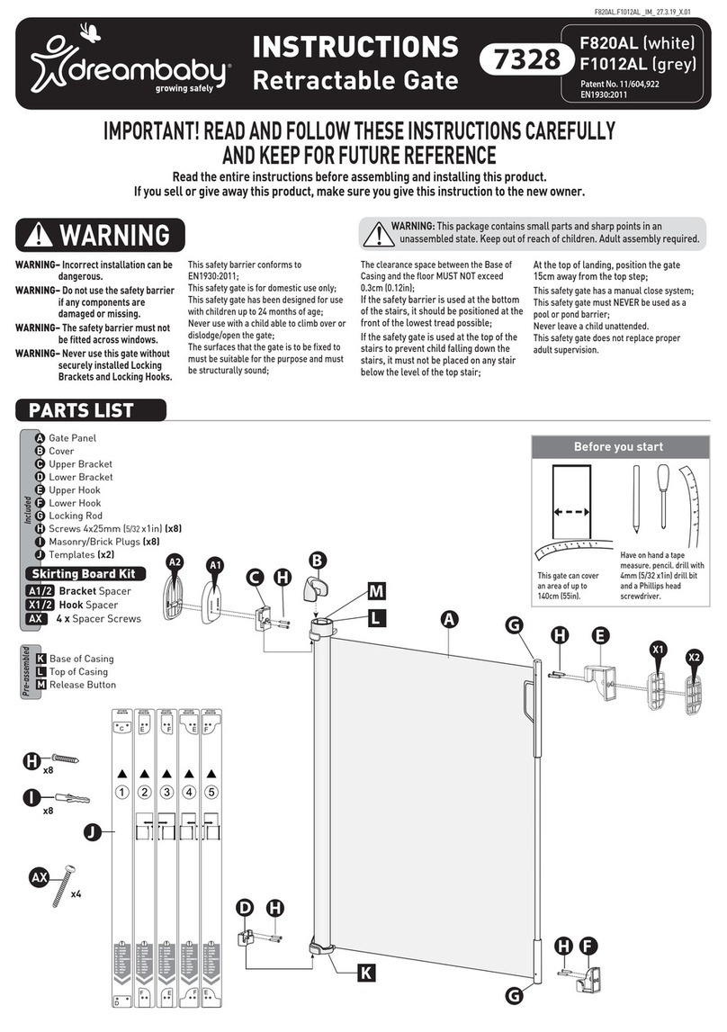
dreambaby F820AL User manual

dreambaby

dreambaby F820AL User manual

dreambaby Chelsea F170 B/W User manual

dreambaby

dreambaby Chelsea F170 B/W User manual

dreambaby Royale Converta LC849 User manual

dreambaby

dreambaby Royale Converta LC849 User manual

dreambaby Boston L2062 User manual

dreambaby

dreambaby Boston L2062 User manual

dreambaby F820NN User manual

dreambaby

dreambaby F820NN User manual

dreambaby F8201 User manual

dreambaby

dreambaby F8201 User manual

dreambaby L.LC.LS265 User manual

dreambaby

dreambaby L.LC.LS265 User manual

dreambaby Maggie G7740 User manual

dreambaby

dreambaby Maggie G7740 User manual

Popular Baby Accessories manuals by other brands

Fisher-Price Bright Expressions Singin' Wigglin' Funhouse instructions

Fisher-Price

Fisher-Price Bright Expressions Singin' Wigglin' Funhouse instructions

BABY DELIGHT Comfy Canopy instruction manual

BABY DELIGHT

BABY DELIGHT Comfy Canopy instruction manual

Lansinoh Breastmilk Storage Bags Instructions for use

Lansinoh

Lansinoh Breastmilk Storage Bags Instructions for use

Philips AVENT SCF640/17 brochure

Philips AVENT

Philips AVENT SCF640/17 brochure

Plebani Abbraccio Assembly and use instructions

Plebani

Plebani Abbraccio Assembly and use instructions

Fisher-Price FPK63 manual

Fisher-Price

Fisher-Price FPK63 manual

GERATHERM Baby ColorChoice Pink Instructions for use

GERATHERM

GERATHERM Baby ColorChoice Pink Instructions for use

Bebe style CCW3016BR instructions

Bebe style

Bebe style CCW3016BR instructions

Fischer-Price M8930 manual

Fischer-Price

Fischer-Price M8930 manual

Chicco One4Ever Snuggle Pod manual

Chicco

Chicco One4Ever Snuggle Pod manual

Stokke Crusi user guide

Stokke

Stokke Crusi user guide

LuvLap SUNSHINE user manual

LuvLap

LuvLap SUNSHINE user manual

Safety 1st IH340 quick start guide

Safety 1st

Safety 1st IH340 quick start guide

Chicco 07 068193 390 000 Instructions for use

Chicco

Chicco 07 068193 390 000 Instructions for use

topmark NICKY T2079 Instructions for use

topmark

topmark NICKY T2079 Instructions for use

bebe-jou 156 manual

bebe-jou

bebe-jou 156 manual

Baby Trend Trend 2.0 instruction manual

Baby Trend

Baby Trend Trend 2.0 instruction manual

Baby Trend Smart Steps WK02 Series instruction manual

Baby Trend

Baby Trend Smart Steps WK02 Series instruction manual

manuals.online logo
manuals.online logoBrands
  • About & Mission
  • Contact us
  • Privacy Policy
  • Terms and Conditions

Copyright 2025 Manuals.Online. All Rights Reserved.