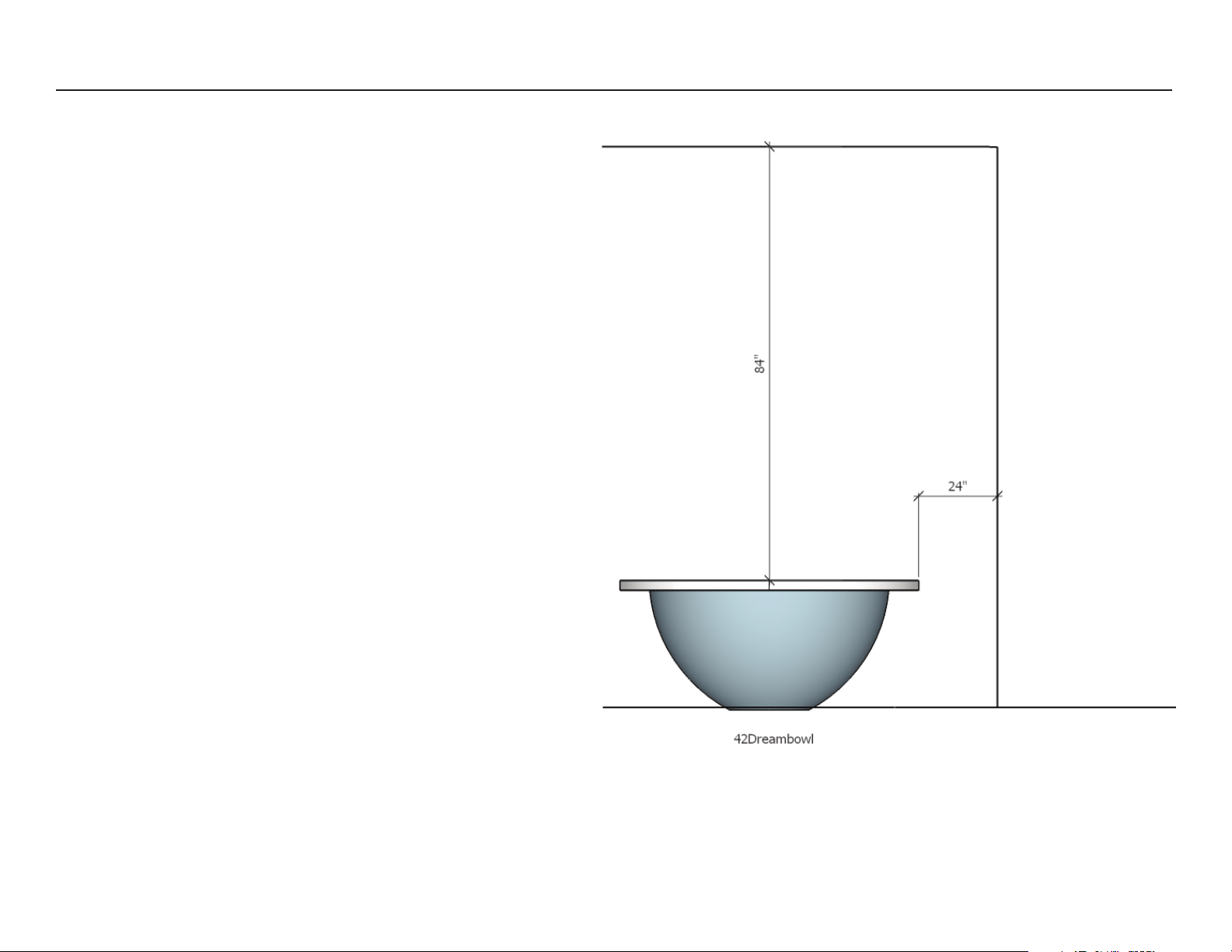
42DREAM FIRE PIT | Installation Manual
pg. 2
SAFETY INFORMATION
⚠WARNINGS:
IM ORTANT: This appliance should
be inspected before use and at
least once annually by a qualified
service person.
More frequent cleaning may
be required as necessary. It
is imperative that the control
compartment, burners and
circulating air passageways of the
appliance be kept clean
DANGER: Carbon monoxide
poisoning can lead to death!
CARBON MONOXIDE OISONING:
Early signs of carbon monoxide
poisoning resemble the flu, with
symptoms including headache, dizzi-
ness, or nausea. If you experience these
signs, the Fire Pit may not be working
properly. Get fresh air at once! ave the
Fire Pit serviced. Some people are more
affected by carbon monoxide than oth-
ers,including pregnant women, people
with heart or lung disease or anemia,
those under the influence of alcohol, and
those at high altitudes.
NATURAL GAS AND RO ANE:
To assist in detecting leaks, an odorant
has been added to natural gas and
propane. owever, this odorant can fade,
and gas may be present even though no
odor exists.
WARNING: Any modification to this appliance or its con-
trols can be dangerous.
1. This appliance, as supplied, is only for use with the
type of gas indicated on the rating plate.
2. When this appliance is connected to a fixed piping
system, the installation must cconform with local codes or, in
the absence of local codes, with the National Fuel Gas Code,
ANSI ZZ223.1/NFPA 54; National Fuel Gas Code, National
Gas and Propane Installation Code, CSA B149.1; or Propane
Storage and andling Code, CSA B149.2, as applicable..
3. Keep the appliance area clear and free from
combustible materials, gasoline and other flammable
vapors and liquids
4. Do not burn solid fuel in this appliance. Do not use
this appliance to cook food or to burn paper or other
objects.
5. Children and adults should be alerted to the
hazards of high surface temperatures and should
stay away to avoid burns or clothing ignition.
6. Clothing or other flammable materials should not
be hung from the appliance, or placed on or near
the appliance.
7. Young children should be carefully supervised
when they are in the area of the appliance.
8. Do not use the appliance if any part has been under water.
Immediately call a qualified service technician to inspect the
appliance and to replace any part of the control system and
any gas control which has
been under water.
9. Inspect the appliance before each use
1. Turn the appliance off and let cool
before servicing, installing, repairing or
covering. Any guard or other protective
device removed for servicing the appli-
ance must be replaced prior to operat-
ing the appliance. Only a qualified
service person should install, service,
or repair the appliance.
HIGH ALTITUDE INSTALLATION
Gas fireplaces are tested and approved
for elevations from 0 to 4,500 feet in
Canada and U.S.A.
When installing this fireplace at an ele-
vation above 4,500 feet (in Canada),
check with local authorities. Consult
your local gas utility for assistance in
determining the proper orifice for your
location.
LOCAL CODES
Install and use your Outdoor Fire Pit
with care. Follow local codes. In the ab-
sence of local codes, use the latest
edition of The National Fuel Gas Code
ANSI Z223.1/NFPA 54 available from:
American National Standards Institute Inc.
1430 Broadway New York NY 10018
National Fire Protection Association,Inc.
Batterymarch Park Quincy MA 02269.
Make certain you read and understand
all warnings. Keep this manual for refer-
ence.