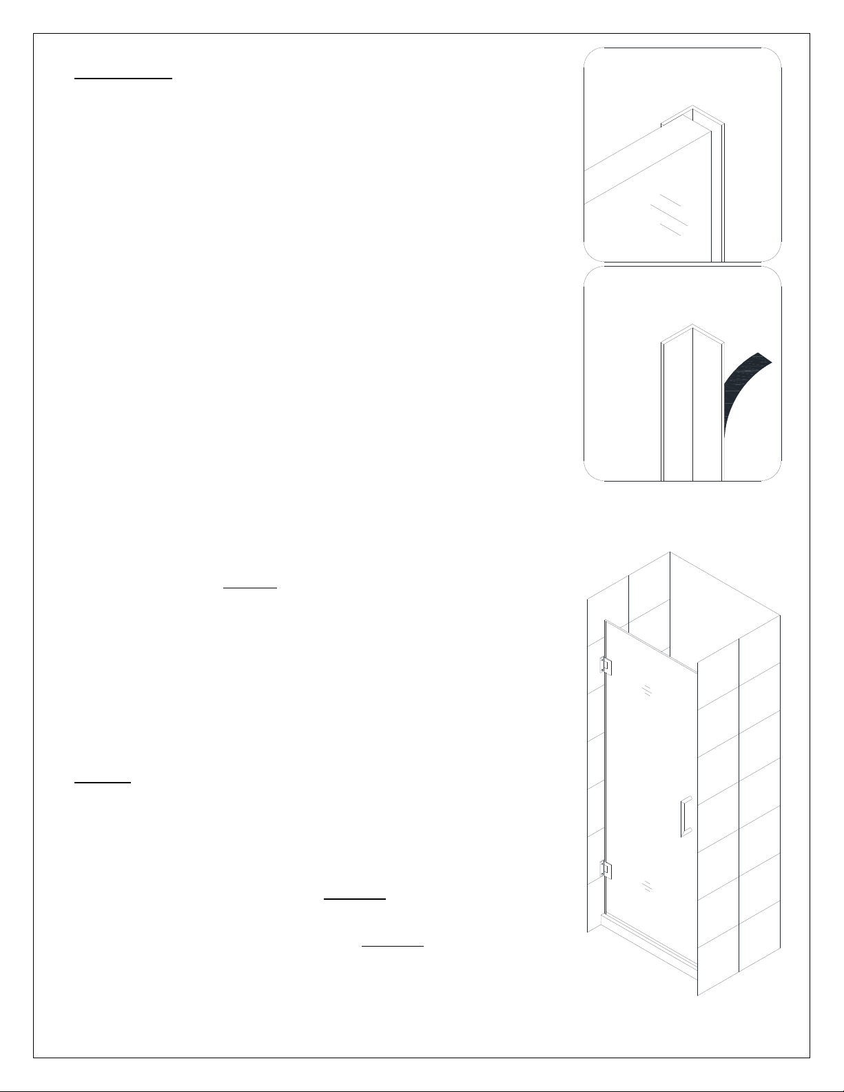
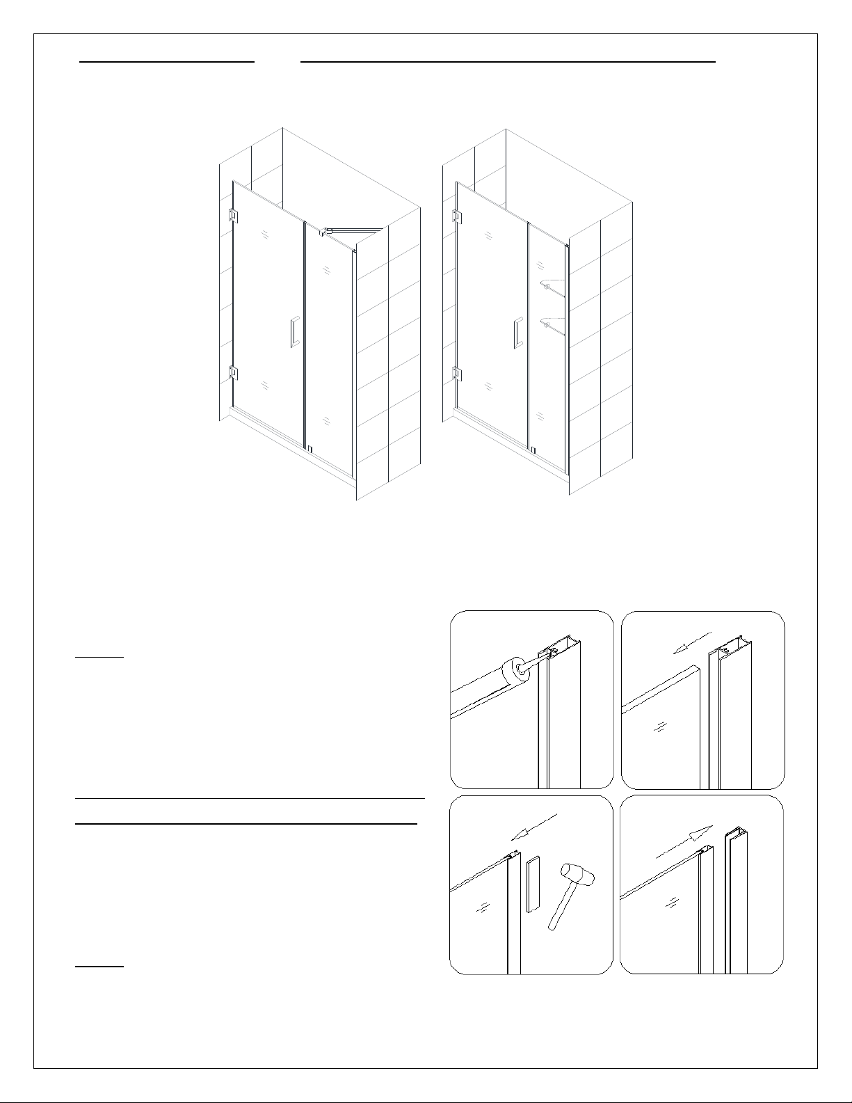
Dreamline UNIDOOR User manual
Other Dreamline Bathroom Fixture manuals

Dreamline
Dreamline ALLIANCE PRO SDAH48W700 User manual

Dreamline
Dreamline ENIGMA User manual

Dreamline
Dreamline ALLIANCE PRO SDAL48W700 User manual

Dreamline
Dreamline PRISM PLUS SHEN-2634340 Series User manual

Dreamline
Dreamline SHCM-2648-00 User manual

Dreamline
Dreamline AQUA UNO User manual

Dreamline
Dreamline SHCM-2358-00 User manual

Dreamline
Dreamline UNIDOOR B User manual

Dreamline
Dreamline BUTTERFLY User manual

Dreamline
Dreamline SHDR-20237210F Series User manual

Dreamline
Dreamline PRISM PLUS User manual

Dreamline
Dreamline SHCM-2718-00 User manual

Dreamline
Dreamline ENIGMA 60" wide User manual

Dreamline
Dreamline Visions User manual

Dreamline
Dreamline Aqua Fold DLT-1132320 User manual

Dreamline
Dreamline QWALL-3 User manual

Dreamline
Dreamline PRISM PLUS User manual

Dreamline
Dreamline ALLIANCE PRO BG SDAB60A700 User manual

Dreamline
Dreamline AQUA PLUS User manual

Dreamline
Dreamline AQUA-Q FOLD SD-363072Q Series User manual


Popular Bathroom Fixture manuals by other brands

Kohler
Kohler Mira Sport Max J03G Installation and user guide

Moen
Moen 186117 Series installation guide

Hans Grohe
Hans Grohe Raindance Showerpipe 27235000 Instructions for use/assembly instructions

Signature Hardware
Signature Hardware ROUND SWIVEL BODY SPRAY 948942 Install

fine fixtures
fine fixtures AC3TH installation manual

LIXIL
LIXIL HP50 Series quick start guide