dresden elektronik deRFusb-23E00 User manual

User Manual
USB Radio Sticks
deRFusb-23E00
deRFusb-23E00 JTAG
deRFusb-23E06
deRFusb-23E06 JTAG
deRFusb-13E00
deRFusb-13E00 JTAG
deRFusb-13E06
deRFusb-13E06 JTAG
Document Version V1.2
2012-07-31

User Manual
Version 1.2
2012-07-31
USB radio sticks deRFusb
www.dresden-elektronik.de
Page 2 of 36
Table of contents
1. Overview .........................................................................................................................6
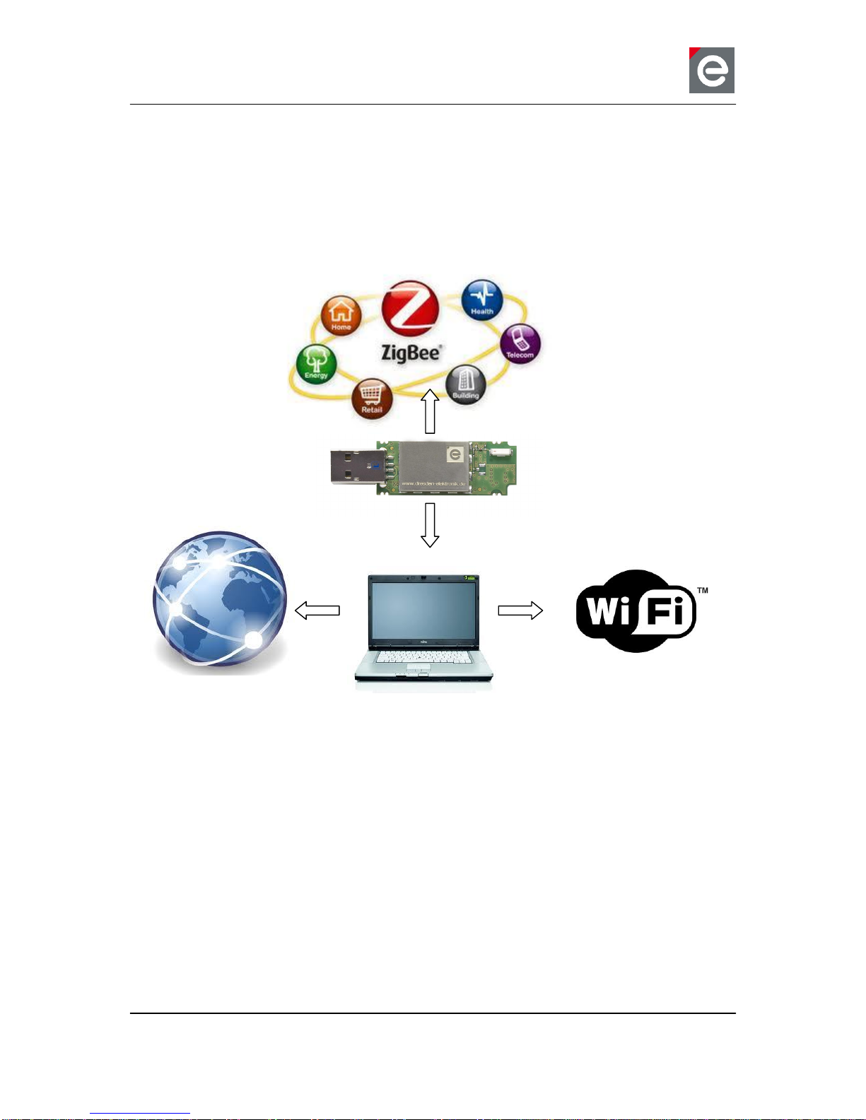
2. Applications.....................................................................................................................7
3. Features..........................................................................................................................7
4. Assembling Options.........................................................................................................9
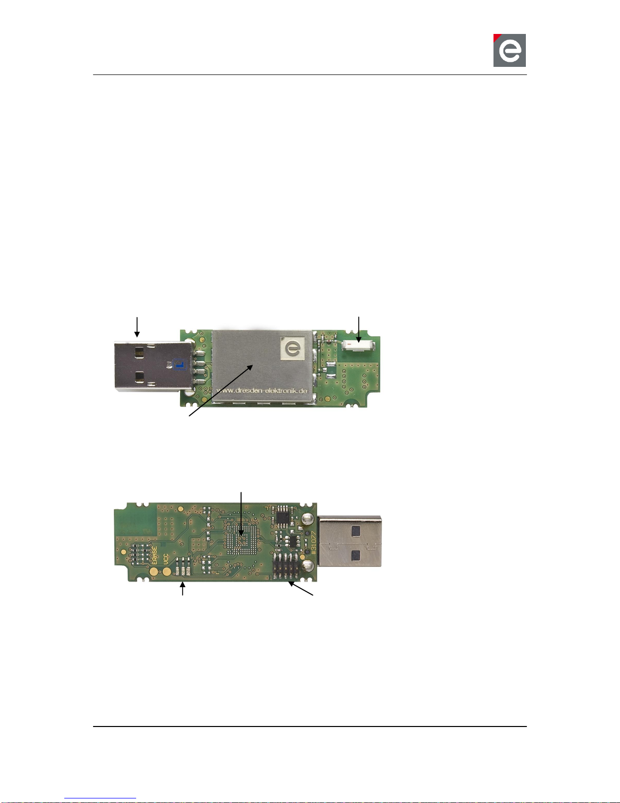
4.1. USB stick for 2.4 GHz application...........................................................................9
4.2. USB stick for Sub-GHz application.......................................................................10
5. Technical data...............................................................................................................11
6. Mechanical size.............................................................................................................15
7. Application environment ................................................................................................16
8. Pin assignment..............................................................................................................17
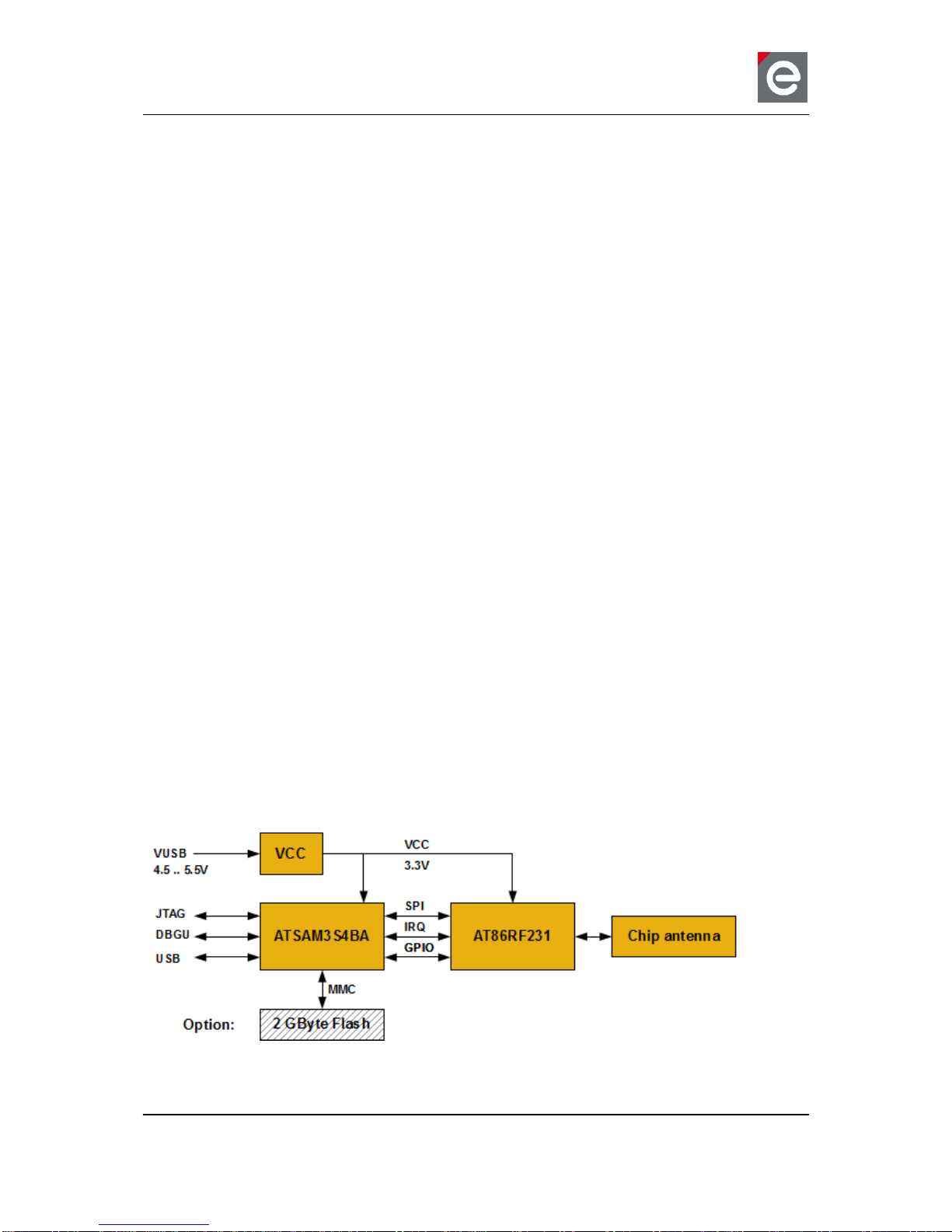
9. On-board transceiver.....................................................................................................20
9.1. General transceiver description............................................................................20
9.2. Internal transceiver connection to the MCU..........................................................21
10. On-board components and peripherals..........................................................................22
10.1.Clock ..................................................................................................................22
10.2.Programmable LEDs............................................................................................22
10.3.ERASE and VCC pins..........................................................................................23
10.4.On-board flash (option).........................................................................................23
10.4.1. Mass Storage Device example....................................................23
10.5.Coaxial connector.................................................................................................26
11. Programming.................................................................................................................27

User Manual
Version 1.2
2012-07-31
USB radio sticks deRFusb
www.dresden-elektronik.de
Page 3 of 36
12. Pre-flashed firmware .....................................................................................................27
12.1.No firmware..........................................................................................................27
12.2.Wireless UART firmware ......................................................................................27
12.2.1. Step-by-Step instructions for Windows........................................28
12.2.2. Step-by-Step instructions for Linux..............................................29
13. Radio certification..........................................................................................................30
13.1.United States (FCC).............................................................................................30
13.2.European Union (ETSI)........................................................................................31
14. Ordering information......................................................................................................33
15. Revision notes...............................................................................................................35
16. References....................................................................................................................35

User Manual
Version 1.2
2012-07-31
USB radio sticks deRFusb
www.dresden-elektronik.de
Page 4 of 36
Document history
Date
Version
Description
2011-06-29
1.0
Initial version
2011-07-01
1.1
Update
- Certification 2.4 GHz USB radio stick, temperature range,
radio data
2012-07-16
1.2
Update
- Technical data, mechanical size, programming, certifica-
tion information added
- Options overview, application environment, programmable
LEDs, clock, pre-flashed firmware, on-board flash, coaxial
connector information added
Author / Check / Release
Firm
Division / Name
Author
DE
Div. / APA
Check
DE
Div. / ML
Release

User Manual
Version 1.2
2012-07-31
USB radio sticks deRFusb
www.dresden-elektronik.de
Page 5 of 36
Abbreviations
Abbreviation
Description
802.15.4
IEEE 802.15.4-standard, applicable to low-rate wireless Personal Area
Network
ADC
Analog to Digital Converter
AES
Advanced Encryption Standard
CE
(Applications) - Consumer Electronics
DAC
Digital to Analog Converter
DBGU
Debug Unit
eMMC
embedded Multimedia Card
ETSI
European Telecommunications Standards Institute
FCC
Federal Communications Commission
GPIO
Generals Purpose Input Output
IC
(Certification) - Industry Canada
ISM
Industrial, Scientific and Medical frequency band
JTAG
Joint Test Action Group
MAC
Medium Access Control
MCU, µC
Microcontroller Unit
MMC
Multimedia Card
MSD
Mass Storage Device
PCB
Printed Circuit Board
PER
Packet Error Rate (measurement)
PWM
Pulse Width Modulation
RF
Radio Frequency
SPI
Serial Peripheral Interface
TRX
Transceiver
TWI
Two-Wire Serial Interface
UART
Universal Asynchronous Receiver Transmitter
U.FL
Miniature coaxial RF connector for high-frequency signals
USART
Universal Synchronous/Asynchronous Receiver Transmitter
USB
Universal Serial Bus
WPAN
Wireless Personal Area Network
WSN
Wireless Sensor Networks

User Manual
Version 1.2
2012-07-31
USB radio sticks deRFusb
www.dresden-elektronik.de
Page 6 of 36
1. Overview
The USB radio sticks by dresden elektronik provide access to the world of IEEE 802.15.4™
technology by being the gateway to almost any IEEE 802.15.4 Wireless Sensor Networks.
Such gateways can be used for monitoring, sniffing or control of wireless ZigBee®or
6LoWPAN networks and are easily adoptable to custom applications due to the available
free stack software.
The compact designed USB radio sticks deRFusb-23E00 and deRFusb-13E00 contain a
powerful CORTEX-M3 microcontroller with 256 kB high-speed flash. Additional 2GB flash
memory to store user defined data is provided using the USB radio sticks deRFusb-23E06
and deRFusb-13E06, it is usable as mass storage device.
Depending on the transmission frequency of 2.4 GHz - deRFusb-23E00/06/JTAG - or
868/915 MHz - deRFusb-13E00/06/JTAG - the ATMEL low-power transceivers AT86RF231
or alternatively AT86RF212 are integrated. They provide a complete radio transceiver inter-
face between the antenna and the microcontroller and an extended functional range such as
a 128-bit AES hardware engine to ensure data security.
For development the USB radio sticks provide a programming and debugging interface to the
user, by default via native USB. For programming via JTAG, the board options deRFusb-
23E00 JTAG, deRFusb-23E06 JTAG, deRFusb-13E00 JTAG and deRFusb-13E06 JTAG are
advised.

User Manual
Version 1.2
2012-07-31
USB radio sticks deRFusb
www.dresden-elektronik.de
Page 7 of 36
2. Applications
The main applications for the USB radio sticks deRFusb-23E00/06/JTAG and deRFusb-
13E00/06/JTAG are:
2.4 GHz and Sub-GHz range IEEE 802.15.4
ZigBee Pro
ZigBee RF4CE
ZigBee IP
6LoWPAN
ISA100.11a
Wireless Sensor Networks (WSN)
Industrial and home controlling and monitoring
Gateway to other network technologies via PC or laptop
3. Features
The 2.4 GHz USB radio sticks deRFusb-23E00/JTAG and deRFusb-23E06/JTAG offer the
following features:
Compact size (in case): 71.0 x 23.0 x 8.7 mm
USB powered
3 free programmable status LEDs (red, yellow, green)
RF shielding
Debugging/programming interfaces: 1 x DBGU and 1 x JTAG with 10-pin connector
assembly option, native USB
On-board transceiver and chip ceramic antenna 2.4 GHz
Option: on-board 2 GB flash
Certification: FCC certified, conformity ETSI/CE
The block diagram (Figure 1) below shows layout and interaction of the main deRFusb-
23E00/06/JTAG components:
Figure 1: Block diagram deRFusb-23E00/06/JTAG

User Manual
Version 1.2
2012-07-31
USB radio sticks deRFusb
www.dresden-elektronik.de
Page 8 of 36
The Sub-GHz USB radio sticks deRFusb-13E00/JTAG and deRFusb-13E06/JTAG offer simi-
lar features:
Compact size (in case): 71.0 x 23.0 x 8.7 mm
USB powered
3 free programmable status LEDs (red, yellow, green)
RF shielding
Debugging/programming interfaces: 1 x DBGU and 1 x JTAG with 10-pin connector
assembly option, native USB
On-board transceiver and chip ceramic antenna Sub-GHz
Option: on-board 2 GB flash
Conformity ETSI/CE
Layout and interaction of the main deRFusb-13E00/06/JTAG components is shown in
Figure 2.
Figure 2: Block diagram deRFusb-13E00/06/JTAG

User Manual
Version 1.2
2012-07-31
USB radio sticks deRFusb
www.dresden-elektronik.de
Page 9 of 36
4. Assembling Options
This section gives a short overview of the different available USB stick options and their as-
sembly parts.
The basic assembly and design options of the USB radio sticks are:
10-pin connector
2 GB flash
4.1. USB stick for 2.4 GHz application
The 2.4 GHz USB stick is available with an optional 10-pin connector and an optional 2 GB
flash memory. In Figure 3 and Figure 4 the deRFusb-23E00 JTAG device is imaged. The
RF shielding covers the microcontroller, the transceiver, the quartz crystals and all necessary
passive components.
Figure 3: Top view deRFusb-23E00 JTAG
Figure 4: Bottom view deRFusb-23E00 JTAG
2.4 GHz chip ceramic antenna
USB plug type A
RF shielding
three status LEDs
Option: 10-pin connector for JTAG and debug
Option: 2 GB flash memory (not shown in the figure)

User Manual
Version 1.2
2012-07-31
USB radio sticks deRFusb
www.dresden-elektronik.de
Page 10 of 36
4.2. USB stick for Sub-GHz application
The Sub-GHz USB stick is available with an optional 10-pin connector and an optional 2 GB
flash memory. In Figure 5 and Figure 6 the deRFusb-13E00 JTAG device is imaged. The
RF shielding covers the microcontroller, the transceiver, the quartz crystals and all necessary
passive components.
Figure 5: Top view deRFusb-13E00 JTAG
Figure 6: Bottom view deRFusb-13E00 JTAG
Sub-GHz chip ceramic antenna
USB plug type A
RF shielding
three status LEDs
Option: 10-pin connector for JTAG
and debug
Option: 2 GB flash memory (not shown in the fig-
ure)

User Manual
Version 1.2
2012-07-31
USB radio sticks deRFusb
www.dresden-elektronik.de
Page 11 of 36
5. Technical data
Table 1: Mechanical data
Mechanical
Radio module
Size (length x width x height)
71.0 x 23.0 x 8.7 mm (in case)
63.5 x 19.0 x 5.5 mm (without case)
63.5 x 19.0 x 9.5 mm (with JTAG, without case)
Weight
13 g (in case)
Connectors
USB
Plug type A
10-pin connector option ‘JTAG’
2 x 5 pins, 1.27 mm (50 mil) pitch
Table 2: Environment
Temperature and humidity
Parameter
Min
Typ
Max
Unit
Operating temperature range
Twork
-20
+70
°C
Operating humidity range
25
80
% r.H.
Storage temperature range
Tstorage
-40
+85
°C
Table 3: Electrical data
Electrical (Supply voltage VUSB = 5.0V)
Parameter
Min
Typ
Max
Unit
Supply voltage
VUSB
4.5
5.0
5.5
V
Current
consumption1
ITXon (TX_PWR = 0x00)
ITXoff
IRXon
51
32
45
mA
mA
mA
1
valid for deRFusb-23E00 / deRFusb-23E00 JTAG / deRFusb-13E00 / deRFusb-13E00 JTAG, see
Table 5 for current consumption of USB sticks with external flash memory

User Manual
Version 1.2
2012-07-31
USB radio sticks deRFusb
www.dresden-elektronik.de
Page 12 of 36
Table 4: Quartz crystal properties
Quartz crystal
Parameter
Min
Typ
Max
Unit
MCU crystal
Frequency
18.432
MHz
Frequency tolerance
+/- 30
ppm
Load capacitance
16
pF
Transceiver crystal
Frequency
16.000
MHz
Frequency tolerance
+/-10
ppm
Load capacitance
9
pF
Table 5: External Flash option
External flash (Supply voltage VUSB = 5.0V)
Parameter
Min
Typ
Max
Unit
Storage size2
2
GB
RW speed
Read/Burst
Read
Write/Burst
Write
908
882
178
192
kB/s
kB/s
kB/s
kB/s
Current
consumption3
(while MCU = Idle
and TRX = Off)
Auto Sleep
Sleep (CMD5)
Read/Burst
Read
Write/Burst
Write
32
32
53
58
87
88
mA
mA
mA
mA
mA
mA
2
2 GB = 2000 MB = 2.000.000 kB
3
valid for deRFusb-23E06 / deRFusb-23E06 JTAG / deRFusb-13E06 / deRFusb-13E06 JTAG

User Manual
Version 1.2
2012-07-31
USB radio sticks deRFusb
www.dresden-elektronik.de
Page 13 of 36
Table 6: Radio data of deRFusb-23E00/06/JTAG
Radio 2.4 GHz (Supply voltage VUSB = 5.0V)
Parameter / feature
Min
Typ
Max
Unit
Antenna
Type
Chip ceramic
Gain
-0.2
+0.5
+0.9
dBi (peak)
Diversity
No
Range4
Line of sight
>200
240
m
Frequency range5
PHY_CC_CCA = 0x0B...0x1A
2405
2480
MHz
Channels
PHY_CC_CCA = 0x0B...0x1A
16
Transmitting
power conducted
TX_PWR = 0x00
+2.8
+3.0
+3.6
dBm
Receiver sensitivity
Data Rate = 250kBit/s
Data Rate = 500kBit/s
Data Rate = 1000kBit/s
Data Rate = 2000kBit/s
- 97
-93
-90
-89
dBm
dBm
dBm
dBm
Data rate (gross)
TRX_CTRL_2 = 0x00
TRX_CTRL_2 = 0x01
TRX_CTRL_2 = 0x02
TRX_CTRL_2 = 0x03
250
500
1000
2000
kBit/s
kBit/s
kBit/s
kBit/s
4
Measured while device plugged into laptop standing on a tripod with a height of 1.4 meters above
ground level and PER≤1%
5
Operating the transmitter at channel 26 requires to ensure a duty cycle ≤29%

User Manual
Version 1.2
2012-07-31
USB radio sticks deRFusb
www.dresden-elektronik.de
Page 14 of 36
Table 7: Radio data of deRFusb-13E00/06/JTAG
Radio Sub-GHz (Supply voltage VUSB = 5.0V)
Parameter / feature
Min
Typ
Max
Unit
Antenna
Type
Chip ceramic
Gain
- 0.7
dBi (peak)
Diversity
No
Range6
Line of sight (915MHz)
Line of sight (868MHz)
>100
>200
120
220
m
m
Frequency range
PHY_CC_CCA = 0x00
PHY_CC_CCA = 0x01...0x0A
906
868.3
924
MHz
MHz
Channels
PHY_CC_CCA = 0x00
PHY_CC_CCA = 0x01...0x0A
1
10
Transmitting
power conducted
TX_PWR = 0x00 @ 915MHz
TX_PWR = 0x00 @ 868MHz
+ 9.0
+ 5.0
dBm
dBm
Receiver sensitivity
Data Rate = 20kBit/s
Data Rate = 40kBit/s
Data Rate = 250kBit/s
-106
-104
-97
dBm
dBm
dBm
Data rate (gross)
TRX_CTRL_2 = 0x00
TRX_CTRL_2 = 0x08
TRX_CTRL_2 = 0x09
TRX_CTRL_2 = 0x2A
20
100
200
400
kBit/s
kBit/s
kBit/s
kBit/s
TRX_CTRL_2 = 0x04
TRX_CTRL_2 = 0x0C
TRX_CTRL_2 = 0x0D
TRX_CTRL_2 = 0x2E
40
250
500
1000
kBit/s
kBit/s
kBit/s
kBit/s
6
Measured while device plugged into laptop standing on a tripod with a height of 1.4 meters above
ground level and PER≤1%

User Manual
Version 1.2
2012-07-31
USB radio sticks deRFusb
www.dresden-elektronik.de
Page 15 of 36
6. Mechanical size
The outer PCB dimensions are the same and not depending on the different USB board op-
tions, for details refer to Table 1. The example shown in Figure 7 is the deRFusb-13E00 /
deRFusb-13E06 radio stick; placed in the case the mechanical size is 71.0 x 23.0 x 8.7 mm
(L x W x H).
All dimensions are in millimeters.
Figure 7: Mechanical dimension top view
The 10-pin connector dimension is shown in Figure 8 as part X2; the displayed antenna type
is the 2.4 GHz USB stick one.
Figure 8: Mechanical dimension side view

User Manual
Version 1.2
2012-07-31
USB radio sticks deRFusb
www.dresden-elektronik.de
Page 16 of 36
7. Application environment
The USB sticks are designed to connect an IEEE 802.15.4 network with the PC and laptop
environment. Today there are different variants of USB ports on laptop and PC devices. The
USB stick dimension is optimized to plug other USB devices in adjacent ports especially in
horizontal or vertical designed USB hubs.
Generally, the radiation pattern of RF devices depends on the placement and the application
environment. The test measurement and certification process was done with a plugged USB
stick on the side of an USB port of a laptop while the display was open. It is recommended to
plug the USB stick sideways at an USB port of a laptop, if applicable. The use of application
setups like USB hubs or USB extension cables may result in a lower transmit and receive
range.
The USB stick can only be directly plugged into type A ports; into a laptop, PC or hub.
Figure 9: Laptop USB port type A

User Manual
Version 1.2
2012-07-31
USB radio sticks deRFusb
www.dresden-elektronik.de
Page 17 of 36
8. Pin assignment
The USB stick has a type A USB plug and an optional 10-pin connector in 1.27 mm pitch for
programming via JTAG interface and tracing via UART. This connector is directly accessible
from the USB stick bottom side, see Figure 10. The internal and external signal connection
to the MCU and transceiver is shown in Table 8. The external available signals are described
in Table 9.
1
10
2
9
1.27 mm (50 mil) pitch
Figure 10: Pin assignment of optional 10-pin connector

User Manual
Version 1.2
2012-07-31
USB radio sticks deRFusb
www.dresden-elektronik.de
Page 18 of 36
Table 8: Pin assignment of deRFusb-23E00/06/JTAG and deRFusb-13E00/06/JTAG
µC Pin
Signal name
Function
Comments
USB connector
56
DDM
USB DM
57
DDP
USB DP
10-pin connector (only available with option ‘JTAG’)
53
PB7/TCK/SWCLK
JTAG TCK
Connector pin 1
-
GND
Connector pin 2
49
PB5/TWCK1/PWML0/WKUP13/TDO
JTAG TDO
Connector pin 3
-
VCC
Connector pin 4
51
PB6/TMS/SWDIO
JTAG TMS
Connector pin 5
39
NRST
/Reset
Connector pin 6
-
VCC
Connector pin 7
30
PA9/URXD0/NPCS1/PWMFI0
Debug RXD
Connector pin 8
33
PB4/TWD1/PWMH2/TDI
JTAG TDI
Connector pin 9
29
PA10/UTXD0/NPCS2
Debug TXD
Connector pin 10
Miscellaneous
13
PA19/RK/PWML0/A15/AD2
LED1
red
9
PA17/TD/PCK1/PWMH3/AD0
LED2
yellow
10
PA18/RD/PCK2/A14/AD1
LED3
green
35
PA5/RXD0/NPCS3
Hardware ID1
34
PA6/TXD0/PCK0
Hardware ID2
32
PA7/RTS0/PWMH3/XIN32
Hardware ID3
2 GB flash memory (only available with option ‘06’)
42
MCDA0
ext. Flash Data 0
52
MCDA1
ext. Flash Data 1
26
MCDA2
ext. Flash Data 2
37
MCDA3
ext. Flash Data 3
38
MCCDA
ext. Flash Command
41
MCCK
ext. Flash Clock
Erase pin
55
PB12/PWML1/ERASE
See Section 11

User Manual
Version 1.2
2012-07-31
USB radio sticks deRFusb
www.dresden-elektronik.de
Page 19 of 36
Table 9: Signal description list
Signal name
Function
Type
Active
level
Comments
Power - USB connector
DDM
USB Full Speed Data –
Analog
Digital
DDP
USB Full Speed Data +
JTAG
TCK
Test Clock
Input
On-board Pull-up
TDI
Test Data In
Input
On-board Pull-up
TDO
Test Data Out
Output
TDM
Test Mode Select
Input
On-board Pull-up
Reset
RSTN
Microcontroller Reset
I/O
Low
Pull-Up resistor
UART0
URXD0
UART Receive Data
Input
UTXD0
UART Transmit Data
Output

User Manual
Version 1.2
2012-07-31
USB radio sticks deRFusb
www.dresden-elektronik.de
Page 20 of 36
9. On-board transceiver
The main difference between the deRFusb-23E00/06/JTAG and the deRFusb-
13E00/06/JTAG USB radio sticks is the built-in 2.4 GHz or alternatively Sub-GHz transceiver
in combination with the appropriate on-board chip antenna. The signal connection between
MCU and transceiver is shown in Table 8.
deRFusb-23E00/06/JTAG - AT86RF231 transceiver
The low-power 2.4 GHz transceiver is designed for industrial and consumer IEEE 802.15.4,
ZigBee, RF4CE, ISA100.11a and high data rate ISM applications. For details refer to [1] in
the reference section.
deRFusb-13E00/06/JTAG - AT86RF212 transceiver
The low-power, low-voltage 800/900MHz transceiver is designed for low-cost IEEE 802.15.4,
ZigBee and high data rate ISM applications available Europe and North America. For details
refer to [2].
9.1. General transceiver description
These single-chip radio transceivers provide a complete radio transceiver interface between
an antenna and a microcontroller.
They comprise the analog radio transceiver and the digital modulation and demodulation in-
cluding time and frequency synchronization and data buffering. The number of external com-
ponents is minimized such that only the antenna, the crystal and decoupling capacitors are
required. The bidirectional differential antenna pins are used for transmission and reception,
thus no external antenna switch is needed.
An internal 128 byte RAM for RX and TX buffers the data to be transmitted or the received
data. Two on chip low dropout voltage regulators provide the internal analog and digital 1.8 V
supply.
The transceivers further contain comprehensive hardware-MAC support (Extended Operat-
ing Mode) and a security engine (AES) to improve the overall system power efficiency and
timing.
Other manuals for deRFusb-23E00
1
This manual suits for next models
3
Table of contents
Other dresden elektronik Radio manuals