DRG BioCheck DxDATA User manual

Page 1of 35

Version 1.0
Page 2of 35
DRG Instruments GmbH
Frauenbergstrasse 18
35039 Marburg
Germany
Technical Support
USA Phone: +1-973-564-7555
USA Fax: +1-973-564-7556
Email: drgsupport@drg-international.com
International Phone: +49(0)6421/1700-0
International Fax: +49(0)6421/1700-50
Email: drg@drg-diagnostics.de

Version 1.0
Page 3of 35
Table of Contents
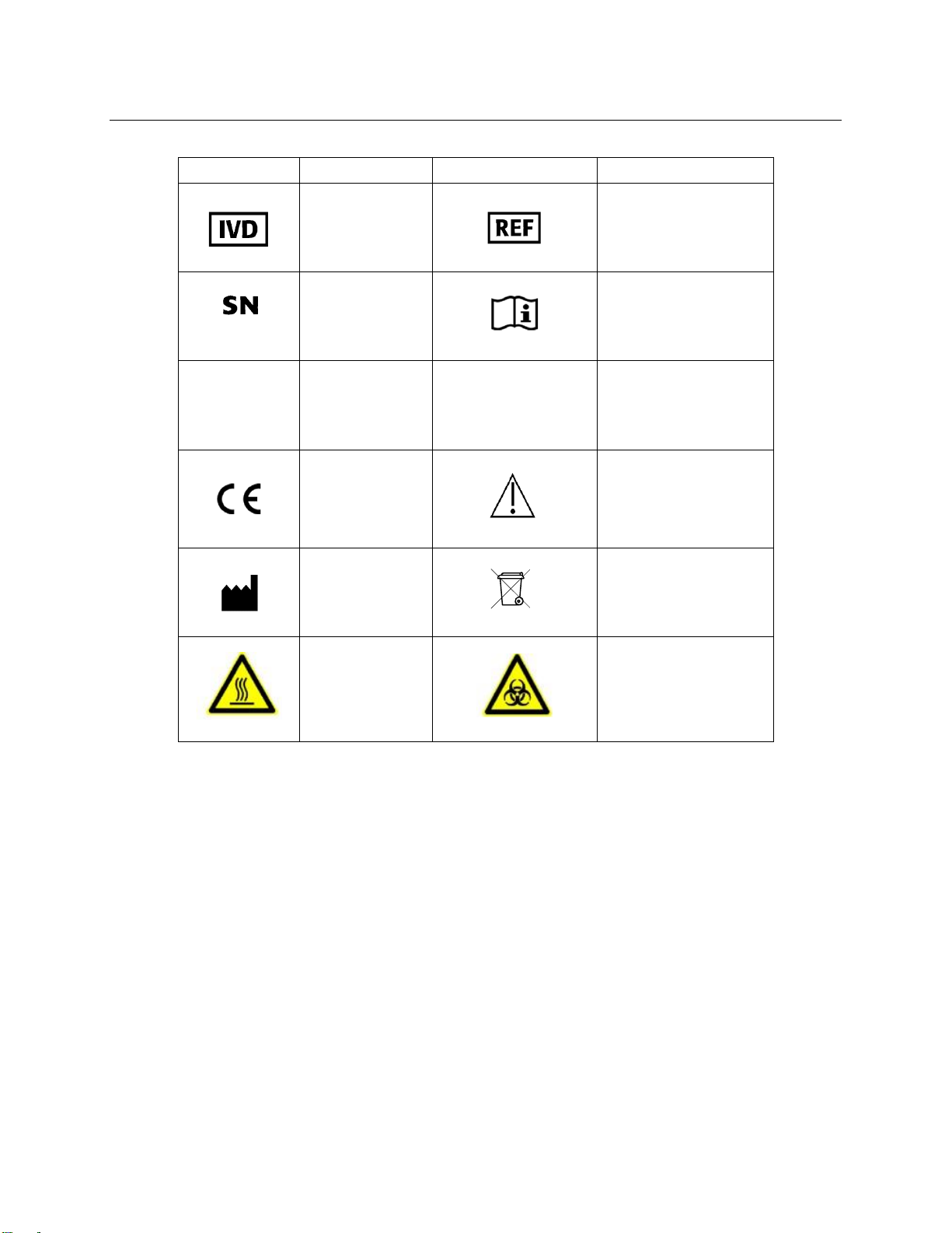
Symbols List ........................................................................................... 4
1. About this manual................................................................................. 5
2. About DxDATATM ................................................................................... 5
2.1 Intended Use................................................................................... 5
2.2 Specifications and performance ............................................................ 6
3. Details of DxDATATM............................................................................... 7
3.1 Principle of detection ........................................................................ 8
3.2 DxDATA TM components....................................................................... 7
4. Storage and Operation of the Equipment.....................................................11
4.1 Environmental conditions and placement instructions .................................11
5. Software Description ............................................................................12
5.1 Software Overview...........................................................................12
5.2 System startup .............................................................................12
5.3 Log in........................................................................................13
5.4 Initialization check ........................................................................14
5.5 Main window ...............................................................................15
5.6 Run window ................................................................................15
5.7 Sample window ............................................................................17
5.8 Results window ............................................................................21
5.9 Settings window ...........................................................................24
5.10 Start initialization.......................................................................30
5.11 Shut down ................................................................................31
6. Instrument warnings and precautions .......................................................32
6.1 Precautions.................................................................................32
7. Troubleshooting ................................................................................33
8. Instrument maintenance ......................................................................35
8.1 Weekly maintenance......................................................................35
8.2 Monthly maintenance .....................................................................35
8.3 Recommended regular maintenance ...................................................35
8.4 Replacing the internal printer paper ...................................................35

Version 1.0
Page 4of 35
Symbols List
Symbol
Description
Symbol
Description
In Vitro
Diagnostic
equipment
Catalog Number
Serial Number
Consult
Instructions for
use
|
Power on
O
Power off
European
Conformity
Caution
Manufacturer
Waste of electrical
and electronic
equipment
High
temperature,
do not touch
these areas
Biological hazard

Version 1.0
Page 5of 35
1. About this manual
This manual contains the necessary information for safe, proper, and effective operation of the
DxDATA TM Automatic Chemiluminescent Immunoassay Analyzing System (hereinafter referred to
as " DxDATA TM "). Please read this manual carefully before operating the DxDATA TM.
2. About DxDATATM
This section includes the intended use, operating characteristics, and instrument performance
of the DxDATA TM.
2.1 Intended Use
DxDATA TM is an automated discrete loading chemiluminescence enzyme-linked immunosorbent
assay (CLIA) and magnetic particle separation analyzing system that uses indirect
chemiluminescence based on a chemiluminescent substrate (APS-5) and alkaline phosphatase
for qualitative or quantitative testing, including immune function, autoantibodies, tumor-
associated antigens, myocardial diseases, hormones, proteins and peptides, sugars and their
metabolites, liver diseases, coagulation markers and other items in human serum, plasma and
whole blood samples.

Version 1.0
Page 6of 35
2.2 Specifications and performance
Instrument type
Automated chemiluminescent immunoassay
analyzing system
Model
DxDATATM
Number of Channels
8-channel parallel detection
Sample material
Whole blood, serum, plasma
Sample volume
30-150l
Wavelength
300-650nm
Data storage
Patient data: more than 100,000 samples (tests)
QC data
More than 100,000 results
Size
400(W) * 610(D) * 645(H)mm
Weight
35 kg
Electrical requirements
110/220 VAC
Rated power supply
110/220V 60/50 Hz 300W
Printer
Built in
Computer
Built in
Screen
10 in LCD touch screen (800 x 600) pixels
Operating System
Microsoft Windows 10 Enterprise

Version 1.0
Page 7of 35
3. Details of DxDATA TM
This section describes the measurement principle, equipment structure, and accessories used
in DxDATA TM.
3.1 Principle of detection
The detection principle used by DxDATA TM is Chemiluminescent Immunoassay (CLIA), and the
reagents used in each test are stored in a special, individually packaged cassette sealed with
aluminum foil.
The DxDATA TM detection principle is described by applying the sandwich immunoassay reaction
mode. The sample is combined with an alkaline phosphatase-labeled antibody and a biotinylated
antibody to form a sandwich structure. The excess streptavidin-coated magnetic particles form
a complex with the biotinylated antibody, and after washing, the luminescent substrate is
catalytically cleaved by an enzyme in the complex to form an unstable excited intermediate.
When the particle returns to the ground state, it emits photons. The light intensity of the
reaction is detected by a photomultiplier tube, and the luminescence intensity of the analyte is
converted into relative light units (RLU) by the instrument operating software.

Version 1.0
Page 8of 35
3.2 DxDATA TM components
This section describes the components of the DxDATA TM and their functions.
3.2.1 Front of the Device
The necessary components for operating the DxDATA TM are located at the front and side of
the unit; see the figure below. Component names and functions are described as follows:
The necessary components for operating the DxDATA TM are located at the front and side of
the unit; see the figure below. Component names and functions are described as follows:
•Touchscreen computer - Displays various information about the DxDATA TM
analyzer and accepts input from the user operating the device.
•Printer - Prints results and other information.
•Swing-up door - Open upwards to insert the reagent strip. The reagent strip information
could be read and the experiment program could be selected automatically via the QR
code auto scanning function.
•External bar code scanner - It is linked directly to the USB port at the backside of the
instrument to read the information contained in the QR code.
Door
Touchscreen
Incubator
Printer
External bar code
scanner

Version 1.0
Page 9of 35
3.2.2 Back of the device DxDATA TM
The supply voltage is 110VAC The supply voltage is 220VAC
The input and output ports of the device are located on the back of the device, as shown in the
figure above.
Switch –This is the main power switch of the device. After the instrument is turned on,
the computer powers up in about 1 minute.
USB –Provides connection to the instrument`s internal computer.
110/220 VAC –Provides connection to the power cable.
Fuse: F2AL250V/F3AL250V –Protects the internal circuitry of the instrument.

Version 1.0
Page 10 of 35
3.2.3 Accessories
Information on the main DxDATA TM accessories is shown in the table below.
Main Accessories Description
Quantity
Remarks
Picture
Power cord
1
Standard
Fuse: F2AL250V/F3AL250V
2
Alternate replacement
Cartridge rack
2
Standard

Version 1.0
Page 11 of 35
4. Storage and Operation of the Equipment
4.1 Environmental conditions and placement instructions
4.1.1 Normal working conditions
1) Altitude: no more than 2000m
2) Power supply voltage DxDATA TM: 110/220V 60/50 Hz 300W
3) Ambient temperature: 10 °C ~ 30 °C; Relative humidity: ≤70%;
4) Atmospheric pressure: 85.0 kPa to 106.0 kPa;
5) Keep away from magnetic field interference sources, e.g., MRIs;
4.1.2 Placement instructions
1) The instrument should be placed on a flat, stable surface.
2) The rear panel of the instrument requires a distance of >200 mm for the power
switch access and ventilation.
3) Avoid placing DxDATA TM in a place where it is exposed to direct sunlight, air
conditioning, or other equipment.
4) Do not block the device vents, and ensure that there is no paper or other objects
that may affect the air circulation in this area.
5) DxDATA TM is placed at an altitude of no more than 2000 meters.

Version 1.0
Page 12 of 35
5. Software Description
5.1 Software Overview
This section describes the software used with DxDATATM instrument.
5.1.1 Software Environment
1) Devise uses a custom 10-inch touch screen, with a resolution of 800X600 pixels.
2) Pre-installed Microsoft Windows 10 Enterprise operating system.
5.2 System startup
Power on the system using the power switch on the back of the instrument.
If the software does not automatically start, double-click the desktop shortcut “DxDATA”.

Version 1.0
Page 13 of 35
5.3 Log in
1) To log in, enter the username and password, you can select option to save the
password. When the "Confirm" button is clicked, the system checks the username and
password, and then login to the system is completed after meeting the system
requirements.
2) Usernames are used to distinguish system permissions: user permissions are divided into
four levels: A, B, C and D.
•Permission A and B: for manufacturing or distributor use only
•Permission C: administrative permissions (user permissions, user settings,
re-collection of calibration curves, etc.)
•Permission D: user permission (sample detection, calibration, quality control,
result query, report printing, adding new batch of reagents)

Version 1.0
Page 14 of 35
5.4 Initialization check
1) After login the system will initialize. A dialogue box will show “Initialization complete” and click
on the “Confirm” button will provide access the main window.
2) If an error, like the ones below, is encountered contact our Technical Support or your local
representative.

Version 1.0
Page 15 of 35
5.5 Main window
1) Click "Run" to enter the device running window
2) Click "Samples" to go to the samples management window
3) Click "Results" to enter the results query window
4) Click "Settings" to proceed to the settings window

Version 1.0
Page 16 of 35
5.6 Run window
The “Run” window is the core part of the normal operation and shows the status of the
instrument. The whole operation process is carried out in this window.
5.6.1 Routine detection settings
All the applicable information such as project, sample and batch number can be manually added
on a channel-by-channel basis in the “Run” window.
1) Double-click a "Project" or "Sample" position to pop up a window for editing.
2) Confirm the correct detection position, select project name, batch number and sample
type (Sample, Calibrator or QC).

Version 1.0
Page 17 of 35
5.7 Sample window
The “Sample” window allows you to add sample and project information for the cartridges as
well as display sample and project information that has been set previously, edit patient
information for samples and more.
5.7.1 Scan Accession number
1) Select the project(s) for the cartridges and scan the accession number into the
“Autoscan” toolbar.
2) If you do not want to add an accession number, the cartridge QR code can be scanned
instead or click Sample Quantity “Add Data” button shown below.
3) Add data
Select the project and enter the number of samples. Click "Add Data" to automatically
fill in "Detection Date", "Channel", "Sample ID" data.
NOTE: Date of testing and results follow the Year-Month-Day format.

Version 1.0
Page 18 of 35
5.7.2 Edit record
1) Double-click the sample record to open information edit interface.
2) Fill in the corresponding data, click the "Continue" button in order to save the current
data and load data for the next cartridge slot.
3) Click the "Cancel" button to cancel the current operation.
4) Click the "Done" button to close the current interface and return to the “Sample” window.

Version 1.0
Page 19 of 35
5.7.3 Set up project portfolio
1) Double-click the “Project portfolio”button at the top to open the portfolio settings
window.
2) Enter the portfolio name and select or deselect the reagents. Blue is selected, white is
deselected. Click the "Confirm" button to save the current item information.
5.7.4 Delete
1) In the “Sample” window select a row sample record and click "Delete" button in order to delete
the sample record.
5.7.5 Historical data
1) In the “Sample” window click “Historical Data” to enter the history interface for sample
information.

Version 1.0
Page 20 of 35
2) Select the testing date range and click “Search” button to display the results of the samples
search.
Double-click the sample record to go to the information edit screen.
5.7.6 Exit
In the “Sample” window click “Exit”button to exit the current interface.
Table of contents
Popular Laboratory Equipment manuals by other brands

DDS Calorimeters
DDS Calorimeters CAL3K-AP installation guide

Sartorius Stedim Biotech
Sartorius Stedim Biotech BIOSTAT CultiBag RM 600 operating manual

JEOL
JEOL JEM1400 Operation

MRC
MRC WBL-100 Operation manual

Thermo Scientific
Thermo Scientific Nicolet Summit user guide

Metrohm
Metrohm Titrando installation instructions