DRIVERITE DR.02.012413 User manual

Unit 626 Kilshane Avenue, North West Business Park, Ballycoolin, Dublin 15, Ireland
Telephone: +353 1 8612 632 Fax: +353 1 8612 647 email:info@driveriteair.com
Web: www.driveriteair.com
DR.02.012413
W21-760-2413
NISSAN NAVARA
D40 Model, 4x4 only
From 2005, ABS Vehicles Only
SEMI-AIR KIT INSTALLATION INSTRUCTIONS

2
50/13 Revision 3
Table of Contents
Table of Contents..........................................................................2
Introduction..................................................................................3
IMPORTANT SAFETY NOTICE ...........................................................3
Special Instructions for Air Connections..........................................3
Kit Contents ..................................................................................4
HARDWARE LIST..............................................................................4
Step by Step Installation ...............................................................5
Step 1: Prepare the Vehicle.............................................................5
Step 2: Prepare the Air Spring assembly .........................................5
Step 3: Air Spring Assembly to Vehicle............................................6
Step 4: Routing the Air Tubing ........................................................7

3
50/13 Revision 3
Introduction
The purpose of this publication is to assist with the installation of the DR.02.012413 kit.
It is important to read and understand the entire installation guide before beginning
installation or performing any maintenance, service or repair. The information here
includes a hardware list and step-by-step installation information.
Drive-Rite reserves the right to make changes and improvements to its products and
publications at any time. Contact Drive-Rite at +353 1 8612 632 or visit us online at
www.driveriteair.com for the latest version of this manual.
IMPORTANT SAFETY NOTICE
The installation of this kit does not alter the Gross Vehicle Weight Rating (GVWR) or
payload of the vehicle. Check your vehicle’s owner’s manual and do not exceed the
maximum load listed for your vehicle.
Gross Vehicle Weight Rating = the maximum allowable weight of the fully loaded
vehicle (including passengers and cargo). This number —along with other weight limits,
as well as tire, rim size and inflation pressure data —is shown on the vehicle’s Safety
Compliance Certification Label.
Payload: The combined, maximum allowable weight of cargo and passengers that the
truck is designed to carry. Payload is GVWR minus the Base Curb Weight.
Precautions
Never exceed the maximum and minimum recommended pressure limits:
Minimum Pressure 1 Bar (14.5 p.s.i)
Maximum Pressure 7 Bar (100 p.s.i)
NEVER DRIVE WITH DEFLATED AIRSPRINGS
Special Instructions for Air Connections
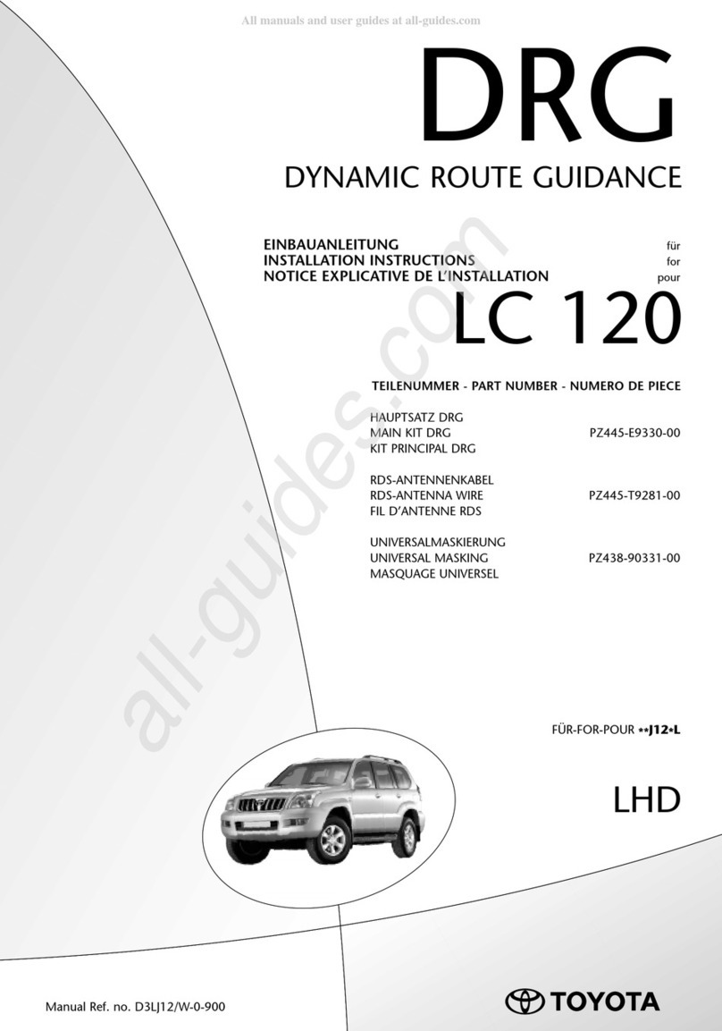
To cut the tubing correctly an appropriate cutter must be used (not scissors)
When inserting the tubing into the connection, it must be pushed in approximately 14mm until
a ‘click’ is heard.
To remove the tube, you must push the flange in on the connection and at the same time pull
the tube. (No tool is necessary.)
ATTENTION, when a tube is removed it is important to trim 14mm from the end before
reconnection.
It is advisable that LOCTITE or similar sealant be used on the threaded fittings.
4
50/13 Revision 3
Kit Contents
HARDWARE LIST

5
50/13 Revision 3
Step by Step Installation
Step 1: Prepare the Vehicle
Place the vehicle on a solid level surface. Take
necessary safety precautions such as using
wheel chocks when working under your vehicle.
Remove the jounce bumpers by cutting them
off as close to the bracket as possible as shown
in the image.
Step 2: Prepare the Air Spring assembly
Select an upper bracket and an air spring from your kit. Attach the upper bracket to the air spring
with a 5/8" nylock nut. Install the male fitting into the air spring. Tighten the air fitting securely to
engage the orange thread sealant (see images below).
Attach the lower bracket to the air spring using the 3/8"-16 x 3/4" hex bolt. Tighten the bolt making
sure the bracket is in the correct position (see images below).
Upper Bracket to Air Spring
Lower Bracket to Air Spring

6
50/13 Revision 3
Step 3: Air Spring Assembly to Vehicle
Place the preassembly on the leaf stack of the left side of the vehicle as shown in the image. (The
image shows the Left Hand Side of the vehicle).
Attach the upper bracket directly beneath the frame rail using the 3/8" - 16 bail clamps and 3/8" lock
nuts. Attach the lower bracket to the leaf stack using the 5 1/2" carriage bolts, 3/8" lock nuts, and
bracket straps, (see image). Follow the same procedures as outlined in steps 1 through 3 for
installing the right side of the vehicle.
Upper Bracket to Chassis
Lower Bracket to Axle

7
50/13 Revision 3
Step 4: Routing the Air Tubing
Cut a long length of tubing in order to connect
the valve to the nearest air spring. Do the same
for the opposite side. Choose whether you want
separate inflation valves for each side or one
valve common to both sides using the T shaped
connector. Use the nylon ties provided to tie the
tubing up into a safe position.
When cutting the air tube, it is vital that the tube
is not cut at an angle. This could cause an air
leak. It is recommended that a tube cutter or a
sharp blade be used.
Drill an 8mm (5/16”) hole and mount the
inflation valve as shown in the diagram, pushing
the valve through the hole from behind and
attaching with 2 washers and a nut.
Cut the air tube to length, making sure the end is
cut squarely, and push the end as far as possible
into the back of the inflation valve.
IMPORTANT:
Attach all tubing securely to the underneath of the vehicle using nylon ties.
Do not attach to brake lines.
Protect the tube with the sleeves provided where there are any sharp edges or sources of
heat.
Ensure all fittings are fastened to recommended torque.
Examination:
After assembly, inflate air springs and check all mounting bolts are tight. Screw all connections tight
again. It must be ensured that the mounting brackets cannot move. If the plates touch the brake
hose at the air springs, then these must be moved by suitable means.

8
50/13 Revision 3
TÜV Report available at www.driveriteair.com or contact Drive-Rite for details
Unit 626 Kilshane Avenue, North West Business Park, Ballycoolin, Dublin 15, Ireland
Telephone: +353 1 8612 632 Fax: +353 1 8612 647 email:info@driveriteair.com
Web: www.driveriteair.com
Table of contents