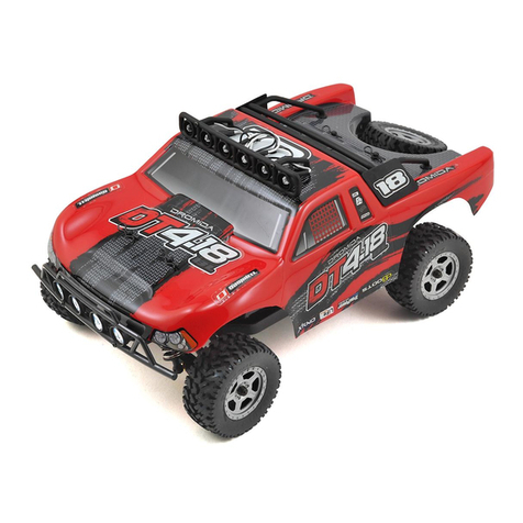
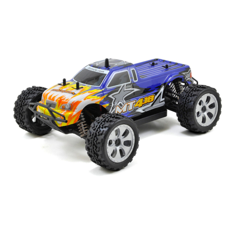
Dromida 1/18 MT/SCT 4WD RTR User manual

Thank you for purchasing the Dromida®1/18 MT/SCT 4WD RTR!
NOTICE
All instructions, warranties and other collateral documents are subject to change at the sole discretion of Horizon Hobby, LLC. For up-to-date
product literature, visit horizonhobby.com or towerhobbies.com and click on the support or resources tab for this product.
Meaning of Special Language
The following terms are used throughout the product literature to indicate various levels of potential harm when operating this product:
WARNING: Procedures, which if not properly followed, create the probability of property damage, collateral damage, and serious injury OR create
a high probability of supercial injury.
CAUTION: Procedures, which if not properly followed, create the probability of physical property damage AND a possibility of serious injury.
NOTICE: Procedures, which if not properly followed, create a possibility of physical property damage AND a little or no possibility of injury.
WARNING: Read the ENTIRE instruction manual to become familiar with the features of the product before operating. Failure to operate the
product correctly can result in damage to the product, personal property and cause serious injury.
This is a sophisticated hobby product. It must be operated with caution and common sense and requires some basic mechanical ability. Failure
to operate this Product in a safe and responsible manner could result in injury or damage to the product or other property. This product is not
intended for use by children without direct adult supervision. Do not attempt disassembly, use with incompatible components or augment product
in any way without the approval of Horizon Hobby, LLC. This manual contains instructions for safety, operation and maintenance. It is essential to
read and follow all the instructions and warnings in the manual, prior to assembly, setup or use, in order to operate correctly and avoid damage or
serious injury.
Age Recommendation: Not for children under 14 years. This is not a toy.
SAFETY PRECAUTIONS AND WARNINGS
As the user of this product, you are solely responsible for operating in a manner that does not endanger yourself and others or result in damage to the
product or property of others.
This model is controlled by a radio signal subject to interference from many sources outside your control. This interference can cause momentary loss
of control, so it is advisable to always keep a safe distance in all directions around your model as this margin will help avoid collisions or injury.
• Never operate your model with low transmitter batteries.
• Always operate your model in open spaces away from full-size vehicles, trafc and people.
• Never operate the model in the street or in populated areas for any reason.
• Carefully follow the directions and warnings for this and any optional support equipment (chargers, rechargeable battery packs, etc.) you use.
• Keep all chemicals, small parts and anything electrical out of the reach of children.
• Never lick or place any portion of the model in your mouth as it could cause serious injury or even death.
• Exercise caution when using tools and sharp instruments.
• Take care during maintenance as some parts may have sharp edges.
• Immediately after using your model, do NOT touch equipment such as the motor, electronic speed control and battery, because they generate high
temperatures. You may burn yourself seriously touching them.
• Do not put ngers or any objects inside rotating and moving parts, as this may cause damage or serious injury.
• Always turn on your transmitter before you turn on the receiver in the car.
• Always turn off the receiver before turning your transmitter off.
• Keep the wheels of the model off the ground when checking the operation of the radio equipment.
NIMH CHARGING WARNINGS
WARNING: Failure to exercise caution while using this product and comply with the following warnings could result in product malfunction, electrical
issues, excessive heat, FIRE, and ultimately injury and property damage.
• NEVER CHARGE BATTERIES OVERNIGHT.
• NEVER LEAVE CHARGING BATTERIES UNATTENDED.
• Read all safety precautions and literature prior to use of this product.
• Never allow children under 14 years of age to charge battery packs.
• Never attempt to charge dead or damaged batteries.
• Never charge a battery if the cable has been pinched or shorted.
• Never allow batteries or charger to come into contact with moisture at any time.
• Never charge batteries in extremely hot or cold places (recommended between 50–80°F (10–26°C)) or place in direct sunlight.
• Always use only Ni-MH rechargeable batteries. This charger cannot charge batteries such as “heavy duty,” “alkaline battery,” “lithium,” or
“mercury battery.”
• Always connect to the charger correctly.
• Always disconnect the battery and charger after charging and let them cool between charges.
• Always inspect the battery before charging.
• Always terminate all processes and contact Horizon Hobby if the product malfunctions.
• Always make sure you know the specications of the battery to be charged or discharged to ensure it meets the requirements of this charger.
• Always constantly monitor the temperature of the battery pack while charging.
• Always end the charging process if the charger or battery becomes hot to the touch or starts to change form during the charge process.
Dromida®1/18 MT/SCT 4WD RTR
Instructions for the Dromida Monster Truck and Short Course Truck
®
MONSTER TRUCK
SHORT COURSE TRUCK

VEHICLE AND RADIO PARTS
BATTERIES
Radio Vehicle
1. Switch off the vehicle and remove the battery.
2. Carefully connect the battery to the charger.
3. Plug the charger into an AC wall outlet.
4. The charging process takes approximately 2 hours. Unplug the
battery when charge is complete.
WARNING: Never leave charging batteries unattended. Only use
the included NiMH charger to charge the included NiMH battery.
Never charge a LiPo battery with a NiMH charger.
1. Steering Wheel Controls direction (left/right) of the model
2. Throttle Trigger Controls speed and direction (forward/brake/reverse) of the model
3. On/Off Switch Turns the power on/off
4. TH Trim Adjusts the throttle trim/dual rates
5. ST Trim Adjusts the steering trim/dual rates
6. CH 3
7. Indicator Lights
Solid Blue Light—Indicates radio connectivity and adequate battery power
Flashing Blue Light—Indicates the battery voltage is critically low. Replace batteries
8. REV Reverses the steering wheel and throttle functions
9. Antenna Transmits the signal to the model
1
2
3
8
4
5
679
This transmitter requires 4 AAA batteries.
1. Remove the battery cover from the transmitter.
2. Install the batteries as shown.
3. Install the battery cover.
CAUTION: If using rechargeable batteries, charge only
rechargeable batteries. Charging non-rechargeable batteries
may cause the batteries to burst, resulting in injury to persons and/or
damage to property.
CAUTION: Risk of explosion if battery is replaced with an
incorrect type. Dispose of used batteries according to national
regulations.
2-n-1 ESC/Receiver Unit
Battery Connector
On/Off Switch
NiMH Battery
M370 Motor
Steering Servo
Charger
Battery

DUAL RATES
DRIVING THE VEHICLE
• To slowly drive forward, pull the trigger slightly. To drive faster, pull
the trigger further.
• To brake, push the trigger. To drive in reverse, push again.
• During a crash, release the trigger.
• To turn, rotate the wheel to the left or right.
• Adjust the steering trim if the car doesn’t track straight (see below).
• When the vehicle battery becomes low, the vehicle will start to slow down.
• Allow the battery to cool before recharging.
• Make sure to turn both the vehicle and the radio off after each use.
• ALWAYS unplug the battery after each use.
Forward Neutral
Left
Right
Brake/
Reverse
Left Right
Forward
Reverse
DRIVING TIPS
• Always release the throttle trigger right away following a crash to prevent damaging the electronics.
• The vehicle should be operated in an open space with no people or animals nearby.
1. Install the battery into the vehicle and
connect the battery.
2. Secure the battery strap to the post using
clips.
3. Switch the radio on.
Steering Dual Rate
1. Power ON the transmitter.
2. Power ON the model.
3. Apply either the left or right steering input on the transmitter and
hold that position.
4. To add or remove steering throw input, continue to hold steering
input while adjusting the dual rate using the (+) or (-) ST button.
Throttle Dual Rate
5. Turn ON the transmitter.
6. Turn ON the model.
7. Apply either forward or reverse throttle input on the transmitter and
hold that position.
8. To add or remove throttle input, continue to hold throttle input while
adjusting the dual rate using the (+) or (-) TH button.
NOTICE: Do not adjust the throttle dual rate while the model is powered
on and resting on a stand. Adjusting the throttle dual rate may power
the motor, which could cause damage to property or personal injury.
The transmitter allows you to adjust steering and throttle dual rates.
LINKING PROCEDURE
To link the radio to the receiver:
1. Turn on the radio, then turn on the vehicle.
2. Press the “BIND” button on the 2-n-1 ESC/Receiver unit and release.
When the LED turns from ashing to solid, the bind is complete.
3. Process is complete.
Bind Button

# Item Description Part Number
1Chassis .....................................................DIDC1028
2Lower Gearbox Half ..................................DIDC1006
3Upper Gearbox Half...................................DIDC1006
4Upper Chassis Brace.................................DIDC1021
5ESC/Rx, 2.4Ghz EC3 .................................HRZ00004
6Servo w/Servo Saver ...............................DIDM1005
7Shock Tower .............................................DIDC1054
8Body Mount...............................................DIDC1054
9Front Hinge Pin Holder .............................DIDC1024
10 Rear Hinge Pin Holder ..............................DIDC1024
11 Battery Hold Down....................................DIDC1026
12 Front Battery Post................... DIDC1028, DIDC1063
13 Suspension Arm........................................DIDC1018
14 Front Hub Carrier ......................................DIDC1012
15 Steering Knuckle ......................................DIDC1013
16 Rear Hub ..................................................DIDC1014
17 2x36.5mm Pin (Inner Hinge) .....................DIDC1035
18 2x22mm Pin (Outer Hinge, Steering) ........DIDC1036
19 Front Bumper............................................DIDC1052
20 Front Bumper Brace .................................DIDC1052
21 Rear Bumper.............................................DIDC1053
22 Rear Bumper Brace ..................................DIDC1053
23 Mud Flap...................................................DIDC1055
24 370 Motor, 40T..........................................DIDC1282
25 Motor Mount .............................................DIDC1031
26 Spur Gear Cover........................................DIDC1027
27 45 Tooth Spur Gear ...................................DIDC1005
28 15 Tooth Differential/Pinion Gear..............DIDC1003
29 Center Drive Shaft ....................................DIDC1007
30 38T Differential Ring Gear ...... DIDC1003, DIDC1061
31 Differential Case ..................... DIDC1004, DIDC1061
32 Diff Bevel Gear (Small)............ DIDC1002, DIDC1061
33 Diff Bevel Gear (Large)............ DIDC1002, DIDC1061
34 2x16.5mm Pin (Diff Gear Pin)....................DIDC1037
DIDC1061
35 Dogbone Spring ...................... DIDC1002, DIDC1062
36 Dogbone....................................................DIDC1009
37 2x5mm O-Ring........................ DIDC1008, DIDC1062
38 Axle...........................................................DIDC1008
39 12T Pinion Gear (.6 Mod, 2mm Shaft).......DIDC1032
40 Ball Stud ...................................................DIDC1034
41 Ball Cup (Long) .........................................DIDC1042
42 Camber Rod ..............................................DIDC1042
43 Tie Rod .....................................................DIDC1042
44 Steering Bell Crank (Right) .......................DIDC1010
45 Steering Ball Crank (Left)..........................DIDC1010
46 Steering Drag Link....................................DIDC1010
47 Ball Cup (Short).........................................DIDC1042
48 Steering Rod .............................................DIDC1042
49 Servo Saver Spline ............... DIDC1199, DIDM1005
50 Servo Saver Base .................. DIDC1199, DIDM1005
51 Servo Saver Spring................ DIDC1199, DIDM1005
52 Servo Saver Arm.................... DIDC1199, DIDM1005
53 Upper Shock Mount ................ DIDC1029, DIDC1067
55 Shock Body...............................................DIDC1016
56 Shock Cap.................................................DIDC1016
58 Shock Shaft ............................ DIDC1066, DIDC1016
59 Shock Seal Retainer ............... DIDC1016, DIDC1067
60 Shock Diaphragm .....................................DIDC1016
61 Shock Piston........................... DIDC1016, DIDC1067
# Item Description Part Number
62 Shock O-Ring............................................DIDC1016
63 Shock O-Ring Spacer.............. DIDC1016, DIDC1067
64 Upper Shock Spring Retainer ...................DIDC1016,
DIDC1067
65 Lower Shock Spring Retainer ...................DIDC1016,
DIDC1067
66 Shock End............................... DIDC1016, DIDC1067
68 Long Shock Spring (Heavy/Orange)..........DIDC1040
69 Shock Pre-Load Spacer 1mm...................DIDC1016
DIDC1067
69 Shock Pre-Load Spacer 2mm...................DIDC1016
DIDC1067
69 Shock Pre-Load Spacer 4mm...................DIDC1016
DIDC1067
70 Wheel/Tire Assembled SC.........................DIDC1056
71 Rear Battery Post.................... DIDC1028, DIDC1063
72 Antenna Tube ............................................DIDC1064
73 Antenna Cap .............................................DIDC1064
HARDWARE
A6x10mm Ball Bearing ...............................DIDC1070
B8x12mm Ball Bearing ...............................DIDC1071
C2x4mm Round Head Screw ......................DIDC1057
E2x8mm Round head Screw.......................DIDC1057
F2x10mm Round Head Screw ....................DIDC1057
G2x8mm Flat Head Screw ..........................DIDC1057
H2x10mm Flat Head Screw ........................DIDC1057
J2x14mm Flat Head Screw ........................DIDC1057
K2.5x8mm Flat Head Screw .......................DIDC1057
L2.5x8mm Socket Head Cap Screw ...........DIDC1057
M2.5x14mm Socket Head Cap Screw .........DIDC1057
N3x6mm Socket Head Cap Screw ..............DIDC1057
P2x8mm Round Head Shoulder Screw.......DIDC1057
Q3x3mm Set Screw ....................................DIDC1057
R3mm Nylon-Insert Lock Nut......................DIDC1001,
DIDC1057
S2.6x5mm Washer......................................DIDC1057
T3x6mm Washer.........................................DIDC1057
U1.5mm E-Clip............................................DIDC1057
VBody Clip (Small)..................... DIDC1000, DIDC1057
X2x6mm S/T Round Head Screw................DIDC1057
This parts list shows the key number, part description, and stock number for the replacement parts sets. When more
than one stock number is listed, that part is available in multiple replacement parts sets.

16
41
42
41
40
13
18
40
25
26
7
53
8
8
40
40
24
17
38
36 39
35
3
35
52
51 50
40
47
5
49
6
38
37
41
56
61
58
55
62
59
64
63
69
68
40
65
66
60
53
40
18
15
34
41
42 12
43
40
31
33 32
16
38
33
30
70
70
19 20
40
8
8
2
53
41
42
41
43
38
15
70
70
35
35
2
10
22
21
3
7
18
53
17
36
48
47
13
17
23
23
13
9
40
28
40
46
18
11
4
18
37
37
40
13
45
17
36
14
40
29
1
40
27 28
40
37
36
71
14
41
42
41
32
44
40
18
40
40
73
72
A
GV
EE
N
F
L
A
T
B
B
L
B
G
E
E
G
H
H
J
J
C
E
E
E
S
L
EE
B
B
E
E
E
V
V
E
E
V
B
B
R
R
R
R
G
G
C
Q
E
E
MS
C
L
E
E
N
T
E
E
E
M
E
E
E
V
SM
SM
B
B
K
K
T
G
G
B
B
E
U
U
C
HH
H
P
G
H
P
V
G
X
X
C
C
We try very hard to have accurate and up-to-date information in this document. Any errors are unintentional.

# Item Description Part Number
1Chassis .....................................................DIDC1028
2Lower Gearbox Half ..................................DIDC1006
3Upper Gearbox Half...................................DIDC1006
4Upper Chassis Brace.................................DIDC1021
5ESC/Rx, 2.4Ghz EC3 .................................HRZ00004
6Servo w/Servo Saver ...............................DIDM1005
7Shock Tower .............................................DIDC1054
8Body Mount...............................................DIDC1054
9Front Hinge Pin Holder .............................DIDC1024
10 Rear Hinge Pin Holder ..............................DIDC1024
11 Battery Hold Down....................................DIDC1026
12 Front Battery Post................... DIDC1028, DIDC1063
13 Suspension Arm........................................DIDC1018
14 Front Hub Carrier ......................................DIDC1012
15 Steering Knuckle ......................................DIDC1013
16 Rear Hub ..................................................DIDC1014
17 2x36.5mm Pin (Inner Hinge) .....................DIDC1035
18 2x22mm Pin (Outer Hinge, Steering) ........DIDC1036
19 Bumper .....................................................DIDC1046
24 370 Motor, 40T..........................................DIDC1282
25 Motor Mount .............................................DIDC1031
26 Spur Gear Cover........................................DIDC1027
27 45 Tooth Spur Gear ...................................DIDC1005
28 15 Tooth Differential/Pinion Gear..............DIDC1003
29 Center Drive Shaft ....................................DIDC1007
30 38T Differential Ring Gear ...... DIDC1003, DIDC1061
31 Differential Case ..................... DIDC1004, DIDC1061
32 Diff Bevel Gear (Small)............ DIDC1002, DIDC1061
33 Diff Bevel Gear (Large)............ DIDC1002, DIDC1061
34 2x16.5mm Pin (Diff Gear Pin)....................DIDC1037
DIDC1061
35 Dogbone Spring ...................... DIDC1002, DIDC1062
36 Dogbone....................................................DIDC1009
37 2x5mm O-Ring........................ DIDC1008, DIDC1062
38 Axle...........................................................DIDC1008
39 11T Pinion Gear (.6 Mod, 2mm Shaft).......DIDC1047
40 Ball Stud ...................................................DIDC1034
41 Ball Cup (Long) .........................................DIDC1042
42 Camber Rod ..............................................DIDC1042
43 Tie Rod .....................................................DIDC1042
44 Steering Bell Crank (Right) .......................DIDC1010
45 Steering Ball Crank (Left)..........................DIDC1010
46 Steering Drag Link....................................DIDC1010
47 Ball Cup (Short).........................................DIDC1042
48 Steering Rod .............................................DIDC1042
49 Servo Saver Spline ............... DIDC1199, DIDM1005
50 Servo Saver Base .................. DIDC1199, DIDM1005
51 Servo Saver Spring................ DIDC1199, DIDM1005
52 Servo Saver Arm.................... DIDC1199, DIDM1005
53 Upper Shock Mount ................ DIDC1029, DIDC1067
55 Shock Body...............................................DIDC1016
56 Shock Cap.................................................DIDC1016
58 Shock Shaft ............................ DIDC1066, DIDC1016
59 Shock Seal Retainer ............... DIDC1016, DIDC1067
60 Shock Diaphragm .....................................DIDC1016
61 Shock Piston........................... DIDC1016, DIDC1067
# Item Description Part Number
62 Shock O-Ring............................................DIDC1016
63 Shock O-Ring Spacer.............. DIDC1016, DIDC1067
64 Upper Shock Spring Retainer ...................DIDC1016,
DIDC1067
65 Lower Shock Spring Retainer ...................DIDC1016,
DIDC1067
66 Shock End............................... DIDC1016, DIDC1067
67 Long Shock Spring (Med Soft/Yellow).......DIDC1038
68 Long Shock Spring (Med Heavy/Blue) ......DIDC1059
69 Shock Pre-Load Spacer 1mm...................DIDC1016
DIDC1067
69 Shock Pre-Load Spacer 2mm...................DIDC1016
DIDC1067
69 Shock Pre-Load Spacer 4mm...................DIDC1016
DIDC1067
70 Left Wheel/Tire/Foam Insert Assembled...DIDC1196
71 Rear Battery Post.................... DIDC1028, DIDC1063
72 Antenna Tube ............................................DIDC1064
73 Antenna Cap .............................................DIDC1064
74
Right Wheel/Tire/Foam Insert Assembled
...DIDC1196
HARDWARE
A6x10mm Ball Bearing ...............................DIDC1070
B8x12mm Ball Bearing ...............................DIDC1071
C2x4mm Round Head Screw ......................DIDC1057
E2x8mm Round head Screw.......................DIDC1057
F2x10mm Round Head Screw ....................DIDC1057
G2x8mm Flat Head Screw ..........................DIDC1057
H2x10mm Flat Head Screw ........................DIDC1057
J2x14mm Flat Head Screw ........................DIDC1057
K2.5x8mm Flat Head Screw .......................DIDC1057
L2.5x8mm Socket Head Cap Screw ...........DIDC1057
M2.5x14mm Socket Head Cap Screw .........DIDC1057
N3x6mm Socket Head Cap Screw ..............DIDC1057
P2x8mm Round Head Shoulder Screw.......DIDC1057
Q3x3mm Set Screw ....................................DIDC1057
R3mm Nylon-Insert Lock Nut......................DIDC1001,
DIDC1057
S2.6x5mm Washer......................................DIDC1057
T3x6mm Washer.........................................DIDC1057
U1.5mm E-Clip............................................DIDC1057
VBody Clip (Small)..................... DIDC1000, DIDC1057
X2x6mm S/T Round Head Screw................DIDC1057
This parts list shows the key number, part description, and stock number for the replacement parts sets. When more
than one stock number is listed, that part is available in multiple replacement parts sets.

16
41
42
41
40
13
18
40
25
26
7
53
8
8
40
40
24
17
38
36 39
35
3
35
52
51 50
40
47
5
49
6
38
37
41
56
61
58
55
62
59
64
63
69
67
68
FRONT
REAR
40
65
66
60
53
40
18
15
34
41
42 12
43
40
31
33 32
16
38
33
30
70
70
19
40
8
8
2
53
41
42
41
43
38
15
74
74
35
35
2
10
19
3
7
18
53
17
36
48
47
13
17
13
9
40
28
40
46
18
11
4
18
37
37
40
13
45
17
36
14
40
29
1
40
27 28
40
37
36
71
14
41
42
41
32
44
40
18
40
40
73
72
A
GV
E
N
F
L
A
T
B
B
L
B
G
E
E
G
H
H
J
J
C
E
E
S
L
EE
B
B
E
E
E
V
V
E
E
V
B
B
R
R
R
R
G
G
C
Q
E
E
MS
C
L
E
E
N
T
E
M
E
E
E
V
SM
SM
B
B
K
K
T
G
G
B
B
E
U
U
C
HH
H
P
G
H
P
V
G
X
X
We try very hard to have accurate and up-to-date information in this document. Any errors are unintentional.

Country of
Purchase Horizon Hobby Contact Information Address
United States
of America
Horizon Service Center
(Repairs and Repair Requests) servicecenter.horizonhobby.com/RequestForm/
2904 Research Rd
Champaign, Illinois, 61822 USA
Horizon Product Support
(Product Technical Assistance)
productsupport@horizonhobby.com
877-504-0233
Sales websales@horizonhobby.com
800-338-4639
What this Warranty Covers—Horizon Hobby, LLC, (Horizon) warrants to the
original purchaser that the product purchased (the “Product”) will be free from
defects in materials and workmanship at date of purchase.
What is Not Covered—This warranty is not transferable and does not cover
(i) cosmetic damage, (ii) damage due to acts of God, accident, misuse, abuse,
negligence, commercial use, or due to improper use, installation, operation or
maintenance, (iii) modification of or to any part of the Product, (iv) attempted
service by anyone other than a Horizon Hobby authorized service center, (v)
Product not purchased from an authorized Horizon dealer, or (vi) Product not
compliant with applicable technical regulations or (vii) use that violates any
applicable laws, rules, or regulations.
OTHER THAN THE EXPRESS WARRANTY ABOVE, HORIZON MAKES NO OTHER
WARRANTY OR REPRESENTATION, AND HEREBY DISCLAIMS ANY AND ALL
IMPLIED WARRANTIES, INCLUDING, WITHOUT LIMITATION, THE IMPLIED WAR-
RANTIES OF NON-INFRINGEMENT, MERCHANTABILITY AND FITNESS FOR A
PARTICULAR PURPOSE. THE PURCHASER ACKNOWLEDGES THAT THEY ALONE
HAVE DETERMINED THAT THE PRODUCT WILL SUITABLY MEET THE REQUIRE-
MENTS OF THE PURCHASER’S INTENDED USE.
Purchaser’s Remedy—Horizon’s sole obligation and purchaser’s sole and
exclusive remedy shall be that Horizon will, at its option, either (i) service,
or (ii) replace, any Product determined by Horizon to be defective. Horizon
reserves the right to inspect any and all Product(s) involved in a warranty claim.
Service or replacement decisions are at the sole discretion of Horizon. Proof
of purchase is required for all warranty claims. SERVICE OR REPLACEMENT
AS PROVIDED UNDER THIS WARRANTY IS THE PURCHASER’S SOLE AND
EXCLUSIVE REMEDY.
Limitation of Liability—HORIZON SHALL NOT BE LIABLE FOR SPECIAL,
INDIRECT, INCIDENTAL OR CONSEQUENTIAL DAMAGES, LOSS OF PROFITS OR
PRODUCTION OR COMMERCIAL LOSS IN ANY WAY, REGARDLESS OF WHETHER
SUCH CLAIM IS BASED IN CONTRACT, WARRANTY, TORT, NEGLIGENCE, STRICT
LIABILITY OR ANY OTHER THEORY OF LIABILITY, EVEN IF HORIZON HAS BEEN
ADVISED OF THE POSSIBILITY OF SUCH DAMAGES. Further, in no event shall the
liability of Horizon exceed the individual price of the Product on which liability is
asserted. As Horizon has no control over use, setup, final assembly, modification
or misuse, no liability shall be assumed nor accepted for any resulting damage
or injury. By the act of use, setup or assembly, the user accepts all resulting
liability. If you as the purchaser or user are not prepared to accept the liability as-
sociated with the use of the Product, purchaser is advised to return the Product
immediately in new and unused condition to the place of purchase.
Law—These terms are governed by Illinois law (without regard to conflict of
law principals). This warranty gives you specific legal rights, and you may also
have other rights which vary from state to state. Horizon reserves the right to
change or modify this warranty at any time without notice.
WARRANTY SERVICES
Questions, Assistance, and Services—Your local hobby store and/or place
of purchase cannot provide warranty support or service. Once assembly, setup
or use of the Product has been started, you must contact your local distributor
or Horizon directly. This will enable Horizon to better answer your questions
and service you in the event that you may need any assistance. For questions
or assistance, please visit our website at www.horizonhobby.com, submit a
Product Support Inquiry, or call the toll free telephone number referenced in
the Warranty and Service Contact Information section to speak with a Product
Support representative.
Inspection or Services—If this Product needs to be inspected or serviced and is
compliant in the country you live and use the Product in, please use the Horizon
Online Service Request submission process found on our website or call
Horizon to obtain a Return Merchandise Authorization (RMA) number. Pack the
Product securely using a shipping carton. Please note that original boxes may
be included, but are not designed to withstand the rigors of shipping without
additional protection. Ship via a carrier that provides tracking and insurance for
lost or damaged parcels, as Horizon is not responsible for merchandise until it
arrives and is accepted at our facility. An Online Service Request is available at
http://www.horizonhobby.com/content/service-center_render-service-center.
If you do not have internet access, please contact Horizon Product Support to
obtain a RMA number along with instructions for submitting your product for
service. When calling Horizon, you will be asked to provide your complete name,
street address, email address and phone number where you can be reached
during business hours. When sending product into Horizon, please include your
RMA number, a list of the included items, and a brief summary of the problem.
A copy of your original sales receipt must be included for warranty consider-
ation. Be sure your name, address, and RMA number are clearly written on the
outside of the shipping carton.
NOTICE: Do not ship Li-Po batteries to Horizon. If you have any issue with a
Li-Po battery, please contact the appropriate Horizon Product Support office.
Warranty Requirements—For Warranty consideration, you must include your
original sales receipt verifying the proof-of-purchase date. Provided warranty
conditions have been met, your Product will be serviced or replaced free of
charge. Service or replacement decisions are at the sole discretion of Horizon.
Non-Warranty Service—Should your service not be covered by warranty,
service will be completed and payment will be required without notification
or estimate of the expense unless the expense exceeds 50% of the retail
purchase cost. By submitting the item for service you are agreeing to pay-
ment of the service without notification. Service estimates are available upon
request. You must include this request with your item submitted for service.
Non-warranty service estimates will be billed a minimum of ½ hour of labor. In
addition you will be billed for return freight. Horizon accepts money orders and
cashier’s checks, as well as Visa, MasterCard, American Express, and Discover
cards. By submitting any item to Horizon for service, you are agreeing to
Horizon’s Terms and Conditions found on our website http://www.horizonhobby.
com/content/service-center_render-service-center.
ATTENTION: Horizon service is limited to Product compliant in the country
of use and ownership. If received, a non-compliant Product will not be ser-
viced. Further, the sender will be responsible for arranging return shipment
of the un-serviced Product, through a carrier of the sender’s choice and at
the sender’s expense. Horizon will hold non-compliant Product for a period
of 60 days from notification, after which it will be discarded.
10/15
WARRANTY
FCC INFORMATION
WARRANTY AND SERVICE CONTACT INFORMATION
FCC Information
FCC ID: 2ARE7-91803
Supplier’s Declaration of Conformity
Dromida 1/18 SC/MT 4WD RTR (DIDC01000/DIDC01001)
This device complies with part 15 of the FCC Rules. Operation is subject to the
following two conditions: (1) This device may not cause harmful interference,
and (2) this device must accept any interference received, including interfer-
ence that may cause undesired operation.
CAUTION: Changes or modifications not expressly approved by the
party responsible for compliance could void the user’s authority to
operate the equipment.
NOTE: This equipment has been tested and found to comply with the limits for
a Class B digital device, pursuant to part 15 of the FCC Rules. These limits are
designed to provide reasonable protection against harmful interference in a
residential installation. This equipment generates, uses and can radiate radio fre-
quency energy and, if not installed and used in accordance with the instructions,
may cause harmful interference to radio communications. However, there is no
guarantee that interference will not occur in a particular installation. If this equip-
ment does cause harmful interference to radio or television reception, which can
be determined by turning the equipment off and on, the user is encouraged to
try to correct the interference by one or more of the following measures:
• Reorient or relocate the receiving antenna.
• Increase the separation between the equipment and receiver.
• Connect the equipment into an outlet on a circuit different from that to
which the receiver is connected.
• Consult the dealer or an experienced radio/TV technician for help.
Horizon Hobby, LLC
2904 Research Rd.
Champaign, IL 61822
Email: compliance@horizonhobby.com
Web: www.horizonhobby.com
©2020 Horizon Hobby, LLC. Dromida, the Dromida logo, and the Horizon Hobby logo are trademarks or registered trademarks of Horizon Hobby, LLC.
All other trademarks, service marks and logos are property of their respective owners.
Updated 07/2020 62819.1 DIDC01000/1001 dromida.com
®
Table of contents
Other Dromida Motorized Toy Car manuals

Dromida
Dromida DB4.18 BL Quick guide

Dromida
Dromida Buggy didc0049 User manual

Dromida
Dromida DIDC0072 Quick guide

Dromida
Dromida SC 4.18 BL User manual

Dromida
Dromida DB 4.18 Quick guide

Dromida
Dromida Monster Truck didc0048 Instruction manual

Dromida
Dromida Short Course Instruction manual

Dromida
Dromida MT 4.18 Quick guide

Dromida
Dromida DT4.18 BL Quick guide

Dromida
Dromida DB 4.18 User manual