DRUCK & TEMPERATUR Leitenberger LR-Cal SOLAR User manual

SOLAR Instructions Manual
- 1 -
Instructions Manual
Temperature Calibrator
LR-Cal SOLAR
DRUCK & TEMPERATUR Leitenberger GmbH
Bahnhofstr. 33
72138 Kirchentellinsfurt / GERMANY
Tel. +49 (0) 7121-90920-0 • Fax +49 (0) 7121-90920-99
E-Mail: DT-Export@Leitenberger.de
www.druck-temperatur.de

SOLAR Instructions Manual
- 2 -
INSTRUCTIONS MANUAL REV. DATE
SOLAR 12.3a 19 Dec 2022
VALID FROM SERIAL NUMBER J810
0
9
INDEX
WARNING...........................................................................................................................................................................3
1 - INTRODUCTION............................................................................................................................................................4
1.1 -PURPOSE AND SUMMARY OF INSTRUCTIONS...................................................................................................................4
2 - SCOPE OF SUPPLY.................................................................................................................................................5
2.1 -NAME:.......................................................................................................................................................................5
2.2 -TECHNICAL DATA:.......................................................................................................................................................5
2.3 -SERVICE (FUNCTION):..................................................................................................................................................6
2.4 -QUANTITY:.................................................................................................................................................................6
2.5 -CONSTRUCTOR:..........................................................................................................................................................6
2.6 -N° OF CORRESPONDENT CATALOGUE SHEET:.................................................................................................................6
2.7 -LIST OF FIRST EQUIPMENT ACCESSORIES:......................................................................................................................6
3 - GENERAL RECOMMENDATIONS................................................................................................................................7
4 - SAFETY INSTRUCTIONS..............................................................................................................................................9
5 - PREPARATION OF OPERATION................................................................................................................................10
5.1 -INSTALLATION...........................................................................................................................................................10
5.1.1 - Removal of packaging....................................................................................................................................10
5.1.2 - Positioning the calibrator................................................................................................................................10
5.1.3 - Supply ............................................................................................................................................................10
5.1.4 - How to fit the equalising block........................................................................................................................10
6 - OPERATION PROCEDURE ........................................................................................................................................12
6.1 -OPERATION DESCRIPTION ..........................................................................................................................................12
6.2 -DESCRIPTION OF INSTRUMENT....................................................................................................................................12
6.2.1 - Thermoregulator.............................................................................................................................................12
6.2.2 - Main switch.....................................................................................................................................................12
6.2.3 - Overheating warning light...............................................................................................................................12
6.2.4 - Ventilation holes.............................................................................................................................................13
6.2.5 - Heating resistance..........................................................................................................................................13
6.2.6 - Equalising block .............................................................................................................................................13
6.2.7 - Temperature sensors .....................................................................................................................................13
6.2.8 - Safety thermostat...........................................................................................................................................13
6.3 -START-UP INSTRUCTIONS ..........................................................................................................................................14
6.4 -USE OF THE FUNCTIONS.............................................................................................................................................17
6.4.1 - Reading the external probes (only for model –2I)...........................................................................................17
6.4.2 - Switch test (SW. ON SW. OFF).....................................................................................................................18
6.4.3 - Serial communication.....................................................................................................................................18
6.5 -RE-CALIBRATION METHODS ........................................................................................................................................18
7 - MAINTENANCE INSTRUCTIONS ...............................................................................................................................19
7.1 -ROUTINE INSPECTIONS INSTRUCTIONS ........................................................................................................................19
8 - SEQUENCE OF MAINTENANCE ...............................................................................................................................19
9 - TYPICAL FAULTS........................................................................................................................................................20
10 - APPENDICES............................................................................................................................................................21
10.1- REGULATION FRONT PANEL......................................................................................................................................21
10.2 -MICROPROCESSOR REGULATOR:CONTROL DESCRIPTION ............................................................................................28
10.3 -COMMUNICATION PROTOCOL RS232/C.....................................................................................................................30
10.4 -LIST OF SPARE PARTS:230V MODEL.........................................................................................................................33
10.5 -DECLARATION OF CONFORMITY AND CHECK REPORT...................................................................................................34
SOLAR Instructions Manual
- 3 -
WARNING
Hazardous voltages are present in this electrical equipment during operation.
Non-observance of the safety instruction can result in severe personal injury or property
damage.
Only qualified personnel should work on or around this equipment after becoming
familiar with all warnings, safety notices, and maintenance procedures contained herein.
Only qualified personnel or our personnel should work on this equipment for
maintenance operation.
The successful and safe operation of this equipment is dependant on proper handing,
operation and maintenance.
Electrical and electronic equipments with this symbol cannot be thrown away in public
dump sites. According to the EU directive 2002/96/EC, the European users of electrical and
electronic equipment have the opportunity to return to the distributor or manufacturer used
equipment purchasing a new equipment. The illegal disposal of electrical and electronic
equipments is punished by pecuniary administrative sanction.
SYMBOLS BEING USED IN THIS MANUAL OR ON THE INSTRUMENT
CAUTION: HOT SURFACE OR PART
CAUTION: REFER TO ACCOMPANING DOCUMENTS
CAUTION: RISK OF ELECTRICAL SHOCK
Note:
In this manual: where not specified, the numbers in parentheses make reference to the annexed
drawing.
SOLAR Instructions Manual
- 4 -
1 - INTRODUCTION
1.1 - Purpose and summary of instructions
This manual contains the instructions for the use and maintenance of the following equipment:
Portable Temperature Calibration mod.: SOLAR.
The instructions reported in this manual, for the above-mentioned equipment, are those relevant to:
* Start-up preparation
* Operation description
* Using of the equipment
* Re-calibration procedure
* Preventive maintenance
* Typical faults and ways of their remedies
Users must observe all the usual safety rules out in this manual for own security and to avoid
equipment failure.
Order Code model SOLAR: 511.0.000.1100.0
Order Code model SOLAR-2I: 511.0.111.1100.0
SOLAR Instructions Manual
- 5 -
2 - SCOPE OF SUPPLY
2.1 - Name:
Portable Temperature Calibrator SOLAR, including accessories, as listed (reference to paragraph 2.7)
2.2 - Technical data:
Environmental range: temperature +10÷+45°C, R.H. max. 80%.
•
Operative range : 200÷+1100°C **. (1000°C for model at 100V)
•
Stability : ±0.3°C**.
•
Display resolution : 0,1/0,01°C
•
Reading precision : ±0.3% ±1 digit V.F.S.
•
Internal probe : Tc type N
•
Auxiliary inputs : Pt100 and thermocouples type J, K, R, S, N( only for version 2I)
•
Interface : RS 232
•
Reading : °C/ °F/K
•
Maximum ascent rate : 18°C/min.**(from 20 to 900°C)
(12°C/min up to 500°C for model with supply 100V,
5°C/min up to 900°C, 2°C/min up to 1060°C)
•
Maximum descent rate : 6/7°C/min.**( from 1000 to 600°C)
3.8°C/min**( from 700 to 400°C)
•
Temperature ramps : min. 0,1°C/1’
•
Stability time : 25 min. (700°C)
•
Dimension of internal oven : ø44x300mm
•
Thermostat test :12 V dc.
•
Radial uniformity@1000°C : ±0.4°C at 40mm from the bottom of the holes
•
Axial uniformity@1000°C : ±0.4°C (extended for 60mm from the bottom of the holes)
•
Power supply : 230V 50/60Hz (115/ by request) 850 VA( 650VA @100V)
•
Size : 170x330xh.450 mm
•
Weight of the calibrator : 11 Kg
•
Structure in flanged plate with handle.
•
Micro-processor operated temperature regulator.
•
Manual resetting safety thermostat.
•
The internal oven consists of a quartz or ceramic tube heated by a ceramic resistance, aluminium
structure.
•
Standard insert Inconel made, ø44mmx175mm dept, fitted with 4 holes 7-9-11-13.5mm in diameter, 155
mm deep. Possibility of special drilling.
•
Thermocouple for regulation and reading.
•
Forced air-cooling system.
•
Upper protection grid.
•
Socket with main cable and protection fuses.
•
Electromagnetic compatibility : Emission EN50081-1
Immunity EN50082-2
NOTE: The data marked with ** has been recorded at an ambient temperature of 20°C±3, power
supply 230V±10%, thermocouples inserted in the block.
The above-mentioned data keep valid for one year after the issuing of the calibrating
certificate; afterwards it is necessary to carry out the oven re-calibration.
MICROPROCESSOR DATA
* Display : 2 lines 20ch x line (3.2x5.5) back lighting.
* processor : 80C552
* A/D converter : Σ-Δ 24 bits
* E2PROM memory for recording parameters.
* RS232 Single serial output.

SOLAR Instructions Manual
- 6 -
2.3 - Service (function):
The portable temperature calibrator Solar has been designed for:
•
Control & calibration of thermocouples, temperature sensors, in the laboratory and in the field, in
conformity with ISO 9000 standard.
•
Thermal test on materials.
The calibrator has been designed to reduce the EMC effect in accordance with the harmonised regulation for
residential, commercial, light industry and heavy industry.
N.B: Pulsar endowed with WindowsTM Software is designed to:
completely check the oven by PC
automatically or manually calibrate many probes
cyclically check temperature sensor long life or stress condition
register and print results obtained according to ISO 9000 standards.
2.4 - Quantity:
1 piece.
2.5 - Constructor:
DRUCK & TEMPERATUR Leitenberger GmbH
Bahnhofstr. 33, 72138 Kirchentellinsfurt, GERMANY, www.druck-temperatur.de
2.6 - N° of correspondent catalogue sheet:
SOLAR
2.7 - List of first equipment accessories:
Standard equipment * SOLAR calibrator
* Standard block Inconel 600 with 4 holes: ø7-9-11-13.5 x155mm.
* Top insulation with 4 holes, h=60mm
* Block extractor
* Electric power cable with CEE plug
* Fuses kit
* Thermostat testing connection cables
* Software AQ2sp Light version
* Instructions manual
* Calibration certificate traceable to SIT standard
* Kit of clamp-screw adapter for bushes (only version 2I)
•
Accessories (optional) * Special inserts available on request.
* Software AQ2sp
* TcS sample probe
* SIT certificate: sample probe connected to Solar
* Carrying case
•
How to order * SOLAR
1 - 110V 50/60Hz
2 - 230V 50/60Hz
00
- Standard version
2I - 2 Input version
•
Certification: all the instruments are supplied with final testing, stability and accuracy certification
traceable to SIT standards (equal do DKD standards).
SOLAR Instructions Manual
- 7 -
3 - GENERAL RECOMMENDATIONS
➔ATTENTION
The processor regulator has been configured in factory with the parameters suited to
work in the respect of the technical specifications.
Don’t change these parameters to avoid malfunction or breaking of the calibrator with risks
of serious personal injury.
This unit is equipped with a power supply cable with polarized plug for alternating
current. This cable allows You to insert the plug in just the right way with the
phase lead in a position defined.
To avoid electric shock, use only the polarized plug of equipment. If necessary,
use only polarized extension cords. Do not use reductions for Shuko plugs or whatever. Do
not use other cables with plugs different from that supplied.
The red lamp 20 indicates the polarity of the phase. Turn the plug in the case the lamp is
on.
- Position of the probe:
N.B: For the positioning of the insert inside the oven, follow the instruction on paragraph 5.
To obtain the best results, follow the advises:
•
Measure the diameter of the probe being checked.
•
Check that the diameter of the hole in the calibration block is at least 1mm bigger than the
diameter of the probe. If this is not the case, use the block with the above-mentioned
tolerances (fig.1).
•
Avoid using holes which are too accurate and do not force the probes into the block.
•
Insert the probe up to the bottom of the block: the sensitive element is in the optimal calibration
zone (fig. 2).
•
When calibrating using probes shorter than the length of the hole in the block, position the
sample reference sensor at the same height as the sensor which is to be checked
•
Calibration with a reference: take care to position the two probes, the standard one and the
calibration one, at the same dept and as close together as possible (fig. 3).
•
Always verify the range of the probes to be calibrated before using; the maximum temperature
of the probes should be higher then the temperature of the liquid otherwise the probe could
break.

SOLAR Instructions Manual
- 8 -
- Advice:
•
The temperature difference is proportional to the difference between the diameter of the probe
and the diameter of the hole.
•
Do not insert the probe when the instrument has already reached the set temperature; thermal
shock causes instability and breakage of the sensitive element.
•
For the calibration of temperature transducer with special execution, call our technical office and
ask for equaliser block with special drillings.
Fig.1 Fig.3Fig.2
SOLAR Instructions Manual
- 9 -
4 - SAFETY INSTRUCTIONS
ATTENTION:
•
Due to the fact that the thermostat is a portable instrument to be used in the field, it is very
important to ensure that the socket has been earthen correctly when connecting it to the
power supply.
•
Carry out the maintenance and repair operation only with the equipment at ambient
temperature and disconnected from the electric power.
•
Do not touch absolutely the metal sheath of the probes when the temperature is higher
than 900°C
•
Don’t touch the probe to calibrate when it’s in the block.
•
After using wait for the stabilisation at ambient temperature before switch off the calibrator.
•
Don’t switch off the calibrator when it works at high temperature because the protection grid
and the carpentry may overheat.
Don’t put anything near the fan-exit (19) because of the hot air when oven is on.
•
When the calibrator must to be moved, remove the block from the quartz or ceramic tube in
order to prevent breakage of the tube.
•
It is a good idea if these operations are carried out with the calibrator as close to ambient
temperature as possible.
•
Never put any type of liquid inside the block.
•
Don’t change absolutely the configuration parameters.
•
Do not connect voltage higher then 5V to the input 4-5-15
•
Don’t put anything on the top of the calibrator.
•
...... use common sense any time.
The equipment adopt the following devices to protect operation from hazard:
•
When there is a breakage in the temperature sensor (8) this is recognised by the thermo-
regulator, which switches off the heat output.
•
Max. temperature safety thermostat (10), with a thermocouple, to disconnect the heating
resistance each time the temperature exceeds 1120°C.
•
Max temperature safety thermostat (11) that disconnect the heating power to protect the
electrical board in the case the fan coil breaks
•
Protection grid to avoid any contact with the internal oven.
•
Protection fuses (3).
•
Ground conductor.
AFTER EVERY USE AT HIGH TEMPERATURE REMEMBER TO SET UP AMBIENT
TEMPERATURE IN ORDER TO COOL DOWN THE CALIBRATOR BEFORE SWITCHING OFF
WARNING: at high temperature near to 1100°C the oven could have a leakage current of
some mA that opens the high sensibility differential main switches. in this case use a
differential switch with sensibility of 30ma or reduce the Mx. temperature
SOLAR Instructions Manual
- 10 -
5 - PREPARATION OF OPERATION
•
Remove the calibrator from the packaging (5.1.1) and place it on a flat surface (5.1.2).
•
Make sure that the instrument has been correctly earthen.
•
Supply the oven with line 230V, 50Hz + earth (5.1.3).
•
Insert the equalising block into the furnace: reference at the instruction on paragraph 5.1.4
•
Before start the calibration read with attention the instruction manual, specially the paragraph 3: -
General recommendation.
5.1 - Installation
5.1.1 - Removal of packaging
The calibrator is equipped with packaging suitable for transport and traditional shipping systems. Any
damage caused during transport must be notified immediately to the carrier and a claim must be made.
The equalising block is packed separately to avoid breaking the quartz or ceramic tube during transport. The
block must be fitted into the calibrator when it is ready to be used.
5.1.2 - Positioning the calibrator
Position the calibrator in a safe clean place; leave enough space around the calibrator to allow the air to
circulate well.
**DANGER: The calibrator is suitable for operating at high temperatures with the consequent danger of
fire. Keep it away from any type of inflammable materials and, never put any type of liquid
inside the block (reference to paragraph 4)
5.1.3 - Supply
The calibrator runs on a voltage of 230 Vac (115V by request), 50/60Hz.
A 2.5mt. cable with CEE polarized plug is supplied with the calibrator fitted with 2 conductors plus earth.
This safety device with polarized plug is designed to reduce the risk of electric shock polarizing the phase of
the power.
Make sure that the plant is earthen correctly before switching the instrument on.
5.1.4 - How to fit the equalising block
After the furnace generally been installed, the equaliser block and the ceramic fiber insulation may be
inserted. Carefully insert the block and the upper insulation into the Quartz or ceramic tube (see annexed
drawing). Care must be taken to prevent dirt or other foreign materials between the block and the quartz or
ceramic tube or it might break during heat up due to thermal expansion differences. The fit between the
block and the tube is typically loose in order to accommodate this expansion.
A handle is provided to insert the block. It consists of a stainless steel rod with a threaded end, which is
screwed into the top of the block. The block is then lowered down over the control and cutout sensor using
the handle allowed to rest on the ceramic fiber insulation on the bottom of the well. There are grooves on
either side of the block for the sensor to slide into. The grooves have a tapered opening at the bottom to
facilitate entry of the sensor.
Insert the ceramic fiber insulation on the top of the block, using the block extractor.
Centre the holes of the upper insulation with the holes of the equalisation block.
* WARNING: To avoid any smell in the room it is better to switch on the calibrator outside the room
for the first time.
Whenever the calibrator has to be moved, remove the block from the quartz or
ceramic tube in order to prevent breakage of the tube.
It is a good idea if these operations are carried out with the calibrator as close to
ambient temperature as possible.
SOLAR Instructions Manual
- 11 -
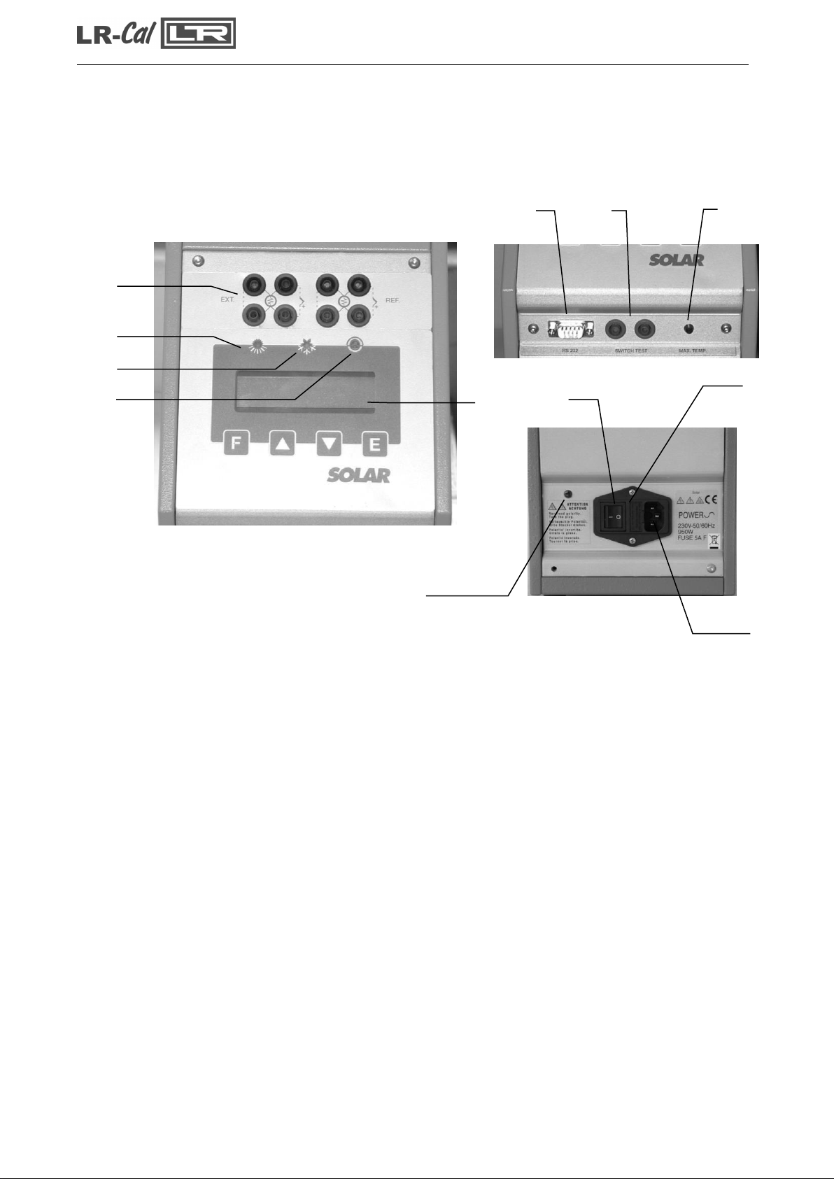
COMMAND LIST
POS. DESCRIPTION
1 SUPPLY SOCKET
2 MAIN SWITCH
3 PROTECTION FUSES
4 SWITCH TEST BUSHES
5 RS-232 SOCKET
6 MAX TEMPERATURE LAMP
7 THERMOREGULATOR +DISPLAY
7.1 HEATING LED
7.2 COOLING LED
7.3 SWITCH TEST LED
15 EXTERNAL PROBES SOCKETS (OPTIONAL)
20 POLARITY SUPPLY INDICATION LAMP
15
7
7.1
7.2
7.3
5 4 6
2 3
1
20
SOLAR Instructions Manual
- 12 -
6 - OPERATION PROCEDURE
6.1 - Operation description
The SOLAR calibrator consist of an equaliser block INCONEL made fitted with holes into which the
sensors to be calibrated are inserted.
A heater element heats the block and an electronic controller with static relay output checks and
regulates the temperature.
A fan is fitted inside the regulating container, which prevents the metal structure from heating.
6.2 - Description of instrument
6.2.1 –Thermo regulator
The thermo-regulator (7) is a PID microprocessor, which can be set from 0 to 1100°C.
•
DISPLAY UPPER LINE: indication of the temperature measured inside the block.
•
DISPLAY LOWER LINE: indication of the set point; external probes if selected, setting
parameters .
•
KEY: used to increment (decrement) any numerical parameter. The increment (decrement)
speed is proportional to the time the key remains depressed.
•
F KEY: allow access to the various parameters (repeatedly press), access to the various
phases of configuration (press F +).
•
E KEY: allow confirming the set parameter.
The calibrator is endowed with eight terminals (optional) that can be set as Pt100 or Tc.
6.2.2 - Main switch
The main switch (2) is fitted with a socket for the supply voltage cable, a main switch and two fuses
of 5A for 230V mod. & 10A for 115V models.
Note: use only fast fuses F. 5X20mm to prevent any danger of fire.
All the electrical parts are protected by the main switch; we recommend allowing the calibrator to
cool before switching it off (reference to paragraph 4)
6.2.3 - Overheating warning light
If the light (6) is “on”, the temperature inside the oven is over in the maximum and the heating
power is off.
The reset of the thermostat is manual:
•
Wait the temperature of the oven to about 900°C or less.
•
Switch off the main switch (2) for few seconds; then switch “on” again to allow the reset of the
thermostat.

SOLAR Instructions Manual
- 13 -
6.2.4 - Ventilation holes
On the base and at the rear of the calibrator holes have been made so that air may circulate inside
the calibrator; do not obstruct these ventilation holes.
6.2.5 - Heating resistance
The resistance is made in ceramic fibre with a spiral-heating element. The power of the resistance
is 850W and it can reach temperatures approaching 1100°C. Bear in mind, however, that
constant use at extreme temperatures reduces the life of the resistance itself. Limit the
number of hours at which the resistance is used at maximum temperatures to the time
required by the calibrator in order to prolong the life of the resistance.
6.2.6 - Equalising block
The equalising block is made in INCONEL; holes have been made on the inside to make it
possible to fit various types of probes. The function of this block is to make the temperature
uniform throughout the depth of the holes so as to be able to calibrate using probes of different
lengths.
Two slots have been made in the block into which the regulating and safety probes are inserted. In
addition to the holes for the test probes, a threaded hole has been made for screwing the extractor.
If you want to fit the calibrator with a block with different holes we recommend that you should
contact the technical support department who will check to see if it is feasible. This will avoid any
unfortunate problems, which might arise if the wrong tolerances are used.
6.2.7 - Temperature sensors
The temperatures sensors used for regulating and protect the instrument are thermocouples. Both
are inserted directly into the equalising block so as to supply a temperature value close to the real
value in the block. There could, however, be some differences due to the tolerances of the
sensors themselves.
6.2.8 - Safety thermostat
The calibrator is supplied with max. temperature safety thermostat (10) that disconnect the heating
system.
In case the thermostat intervenes:
Waiting the cooling of calibrator: the temperature must decrease at least 60÷80°C respect to
maximum set point.
Switch off the calibrator then switch on again a few second later on.
If problem persist: disconnect the electrical cable to the oven and proceeding to repair of eventual
faults (reference to paragraph 4); therefore switch on the oven. Consulting chapter 9 –typical faults
–for any problems on the thermostat.
N.B.: the thermostat mounted on standard ovens has been calibrated in factory to intervene at
1120°C ±10°C
SOLAR Instructions Manual
- 14 -
6.3 - Start-up instructions
ATTENTION:
•
The calibrator can only be used correctly if the user has a good knowledge of its basics.
•
Before starting with the calibration following the instructions for the positioning of the equalising
block (paragraph 5); carefully read paragraph 3 and 4.
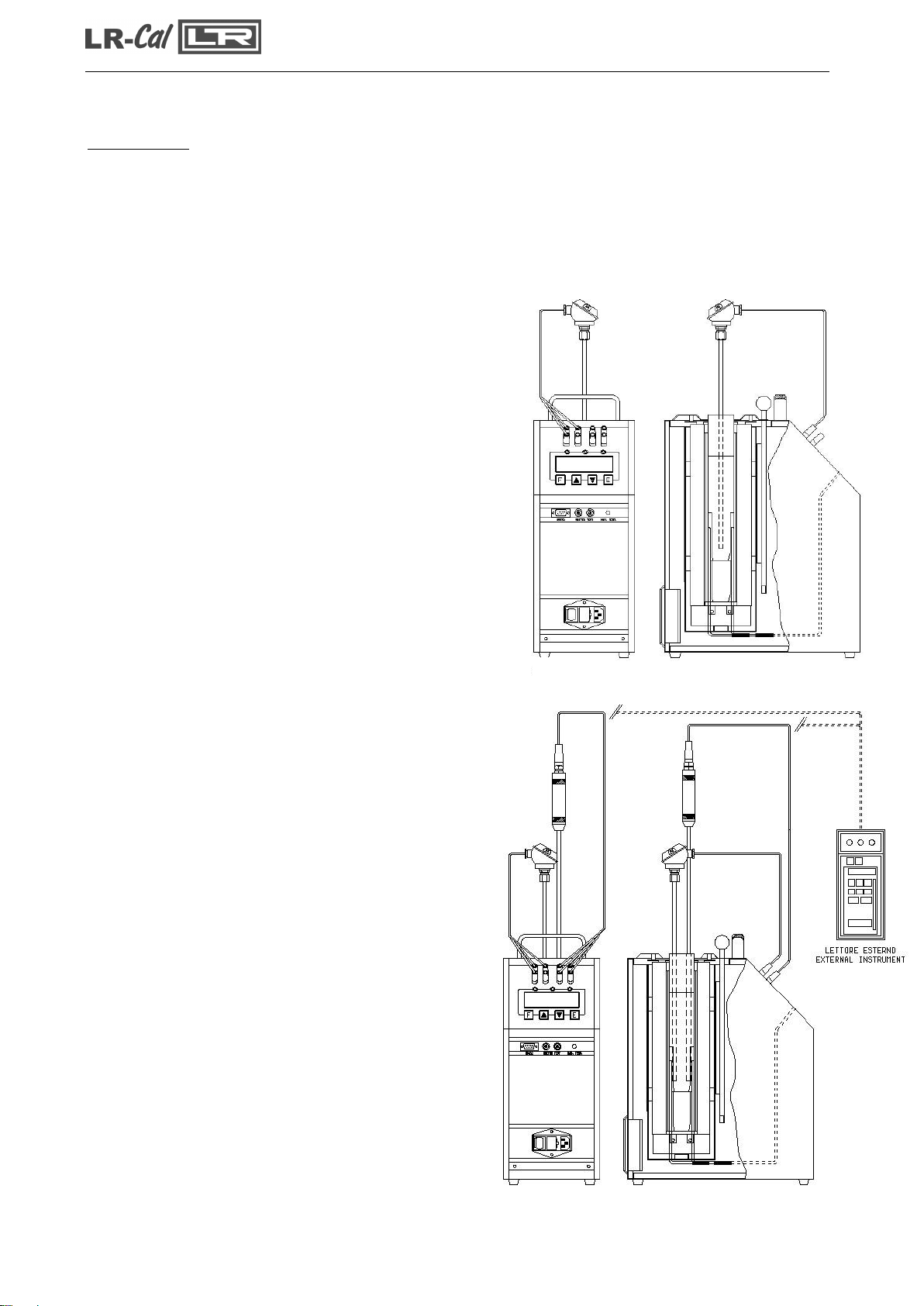
To calibrate the probe it is possible to follow two ways: calibration with internal indicator (7), or
calibration with external reference.
Calibration with the internal indicator (7):
Make reference to the temperature value of the
display (7: fig.4).
It is opportune to refer the value to the test report to
compensate the error of the display.
Calibration with external reference and reading
on the calibrator display:
Make reference to the temperature value of the
external standard instrument inserted in the
equalizer block and connected directly to the Solar
(Fig.5); temperature is read on the second line of
display (for the configuration of the external
reference seeing 10.1). When possible: put the
sensitive elements of the probes near and at the
same dept (reference to Fig.3)
Calibration with external reference and reading
on an external instrument:
Make reference to the temperature value of the
external standard instrument inserted in the
equalizer block and connected to an external
instrument (Fig. 5). When possible: put the sensitive
elements of the probes near and at the same dept
(reference to fig.3).
Fig.4
Fig.5

SOLAR Instructions Manual
- 15 -
Before any calibration follow the general recommendation:
•
Starting the calibration only at ambient temperature: thermal shock can break the sensitive
element of the probe and cause harm to operator.
•
To fit the equaliser block inside the oven: reference to paragraph 5.1.4.
•
Put the probe to check into the equaliser block: reference to chapter 3 (fig 1-2).
•
Push on the main switch (2) and waiting for the end of autotest procedure.
•
Set the required temperature value on the set point following the instructions below:
Press the key to increment the set point value.
Press the key to decrement the set point value.
Press the Ekey to confirm
•
Wait for the stabilisation of the oven before starting any calibration (symbol ÷on the first line of
the display).
•
To working at different temperatures set the set point at the new value and wait for the
stabilisation.
•
When the set point is changed, the temperature read on the display and that measured in the
block may not proceed at the same speed; this is because there are differences between the
sensors used and the position of the same inside the block.
•
The temperature indicated by display, during the item above, must not be considered as a
reference temperature but only as a general indication of the temperature inside the block.
We suggest to insert a primary standard with SIT certificate in the block; compare the measure
with the values indicated by the standard.
Don't ever use the primary standard: it's possible to calibrate the instrument to more significant
points, comparing the displayed temperature with the temperature of the primary standard.
ATTENTION:
•
At the end of the calibration DO NOT remove the probe if it is still at high temperature.
Always allow the calibrator to cool off with the probe still inserted in order to avoid thermal
shock to the probe itself and harm to people or things.
•
Before switch off the calibrator make sure that the temperature of the block is almost the
same as ambient temperature.
SOLAR Instructions Manual
- 16 -
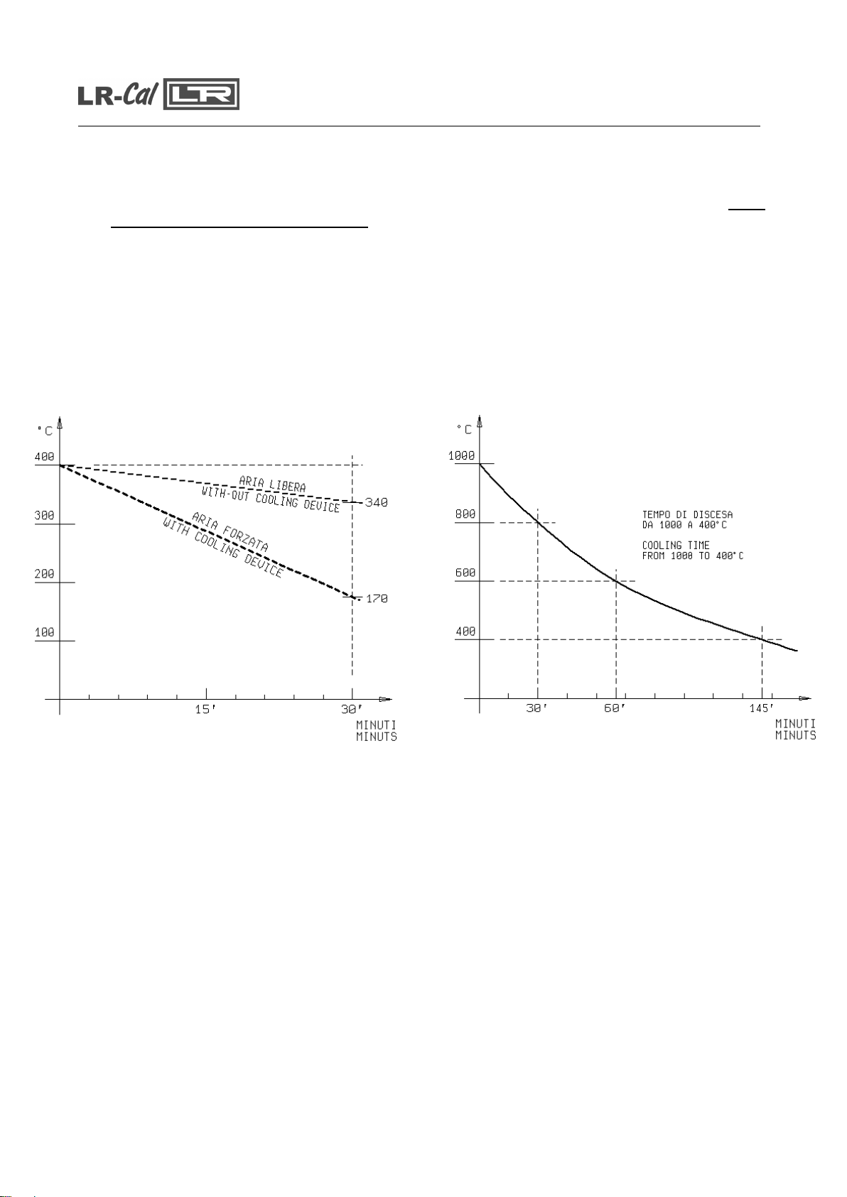
Cooling:
To reduce the oven’s temperature, change the set point and wait for the cooling.
By request the solar with the standard block may be completed with the cooling device using
only with max. temperature of 650°C.
How to use:
•
Insert in the block the cooling device only with the temperature under 650°C
•
Supply with forced air at 3 bar.
•
Set the airflow with the pin valve.
The diagram reported below shows the cooling times with and without the cooling device.
Fig.6 Fig.6a
SOLAR Instructions Manual
- 17 -
6.4 - Use of the functions
6.4.1 - Reading the external probes (only for model –2I)
It is possible to display one or two probes tied to the EXT and REF
inputs.
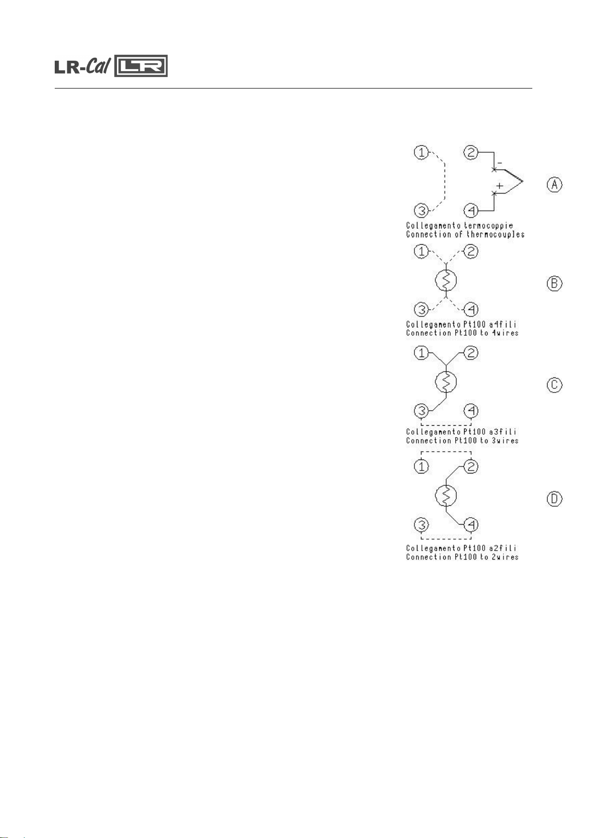
The following probes can be connected:
1.THERMOCOUPLES TYPE J, K, R, S, N with automatic
compensation of the terminal clamp temperature.
2.THERMAL RESISTANCE Pt 100 to 2, 3 or 4 wires.
•
Connect the probe’s wires to the clamps as it is indicated in the
figures.
Thermocouple –connect the wires to the clamps 2-4 to make
attention to the polarity; connect the clamps 1-3 as indicated.
Reference to Fig. 7-A
Pt100 to 4 wires –connect the clamps 1-2-3-4 as indicated in
Fig. 7-B
Pt100 to 3 wires –connect the wires to clamps 1-2-3; connect
the clamps 3-4. Reference to Fig. 7-C
Pt100 to 2 wires –connect the wires to clamps 2-4; connect
the clamps 1-2 & 3-4. In case of two wires connections
remembers to us shortest wires possible. Refer to Fig. 7-D
•
In order to read the external probe’s temperature press the Fkey
up to read SENSOR, select EXT or REF or EXT + REF then
confirm with E key. Press theand Fkeys together to jump to the
second level of the parameters, press Fto read EXT SENSOR
TYPE and REF SENSOR TYPE and press the and the keys
to select the probe; the temperature will be displayed on the at the
bottom of the display.
•
Press theand Fkeys together to jump to the first level again , the
temperature will be indicated on the bottom of the display.
•
In order to read in the '°F' way, refer to the procedure explained in
paragraph 10.1 till Units°C/°F/K; the conversion of the new scale
will be carried out at once.
NOTE: The calibrator always thermally adjusts with the control probe
situated inside the block.
MESSAGE OF ERROR OF THE EXTERNAL PROBES DISPLAY
The display in the case of connection or configuration errors indicates:
EST SENSOR FAIL : wrong connection or configuration of the EXT probe
REF SENSOR FAIL: wrong connection or configuration of the REF probe
SENSORS FAIL: wrong connection or configuration of the REF and EXT probes
Fig. 7

SOLAR Instructions Manual
- 18 -
6.4.2 - Switch test (SW. ON SW. OFF)
It is possible to control the intervention point of thermostats by the 'SWITCH TEST' function.
•
Insert the thermostat’s end in the most suitable hole of the calibrator pit (refer to notes in
paragraph 3).
•
Connect the thermostat’s electrical terminals to the bushes terminals (4).
•
Turn the equipment on.
•
Sent the thermostat intervention temperature and check the release by the lighting of the
indication light (7.3).
•
The thermostat’s release values are recorded. In order to display the recorded value, refer to
the procedure explained in paragraph 10.1 till ‘SW ON - SW OFF’.
•
Press the and keys at the same time in order to reset the 'SW.ON - SW.OFF' values.
•
Refer to paragraph 10.1 to set the ascent and descent ramps.
6.4.3 - Serial communication
On the front of the calibrator there is a 9 pole socket (5) connected to the thermo-
regulator, which enables the calibrator to be completely controlled by a PC
(reference to fig.8). The standard adopted RS-232 (contact the technical
department for the communication number).
The external PC must be conform to the IEC950 standard.
6.5 - Re-calibration methods
To have instrument always efficient is opportune to re-calibrate it periodically.
Frequency of re-calibration is depending to the use of instrument; however we suggest to re-
calibrate the furnace every year.
Fig.8

SOLAR Instructions Manual
- 19 -
7 - MAINTENANCE INSTRUCTIONS
7.1 - Routine inspections instructions
•
Check that the holes of the calibrator are cleaned, any liquid or oil inside the hole could make
oxides or dirty during the use at high temperature.
•
Check once a year the calibration date. Frequency of calibration is depending to the use of
instrument; however we suggest to calibrate the instrument every year.
•
To re-calibrate the instrument is necessary to have a standard temperature instrument, the
software ‘CALIBRA’ and follow the instructions of the software or alternately follow the
instructions of item 10.1.
8 -SEQUENCE OF MAINTENANCE
Not applicable
SOLAR Instructions Manual
- 20 -
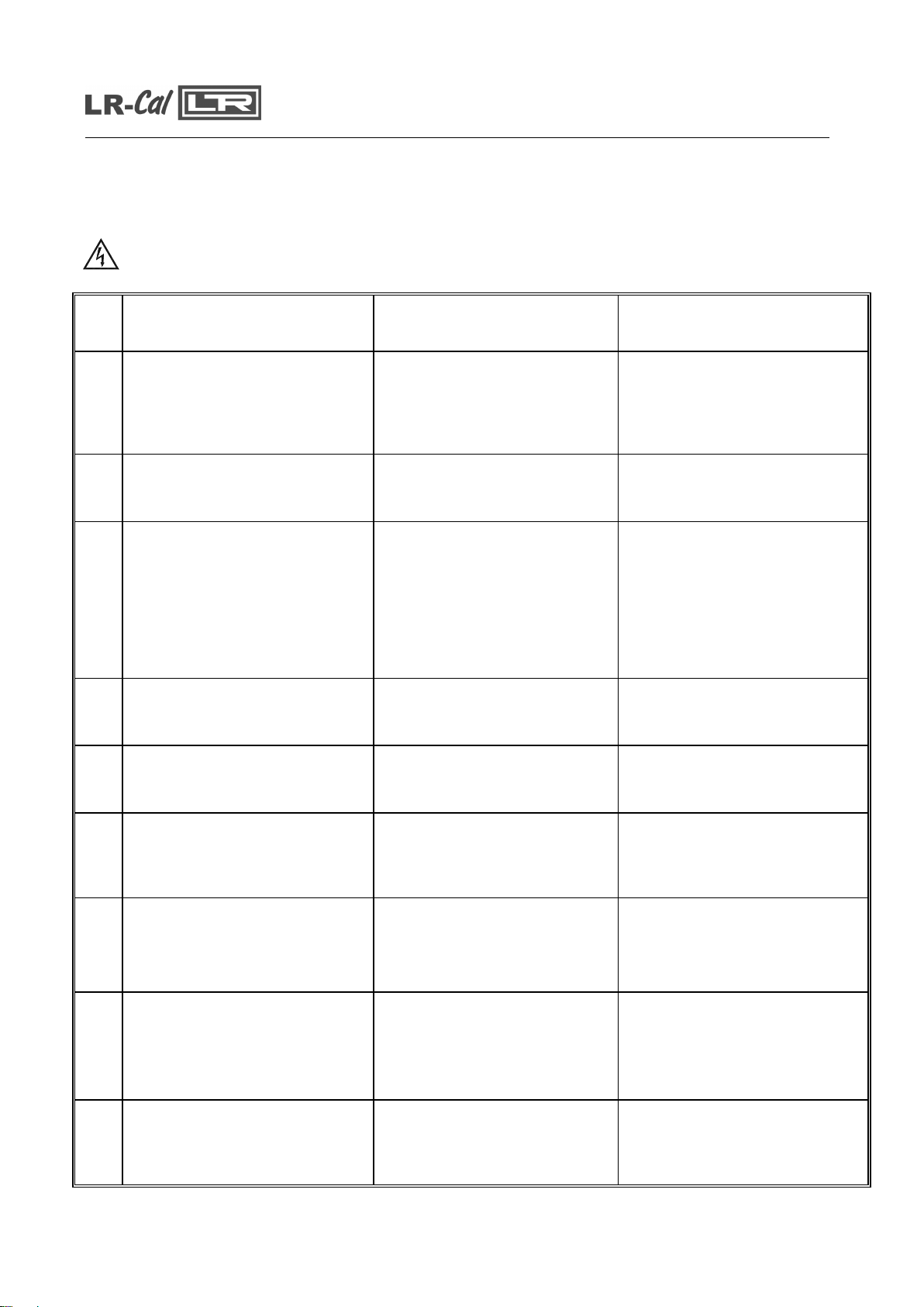
9 - TYPICAL FAULTS
Before carrying out these operations the instrument must be disconnect from the electricity supply; the
equaliser block must be at ambient temperature.
N°
FAULT DESCRIPTION
FAULTY COMPONENT OR
FUNCTION
METHOD FOR REMOVAL
1
The calibrator does not work
when the power cable is
connected and the main switch is
turned on.
- The fuse (3) is cut off.
- The power cable is cut off.
- The main switch is faulty.
- Replace the fuses.
- Replace the power cable with a
similar one.
- Replace the cup socket (1-3)
2
The fuses (3) are triggered when
the power cable is connected
and the main switch is turned on.
- The main switch is faulty.
- There is a short circuit in the
heating element.
- Replace the cup socket.
- Contact our technical office.
3
The control panel is working
properly but the temperature
does not increase.
- The static relay on the supply
card (12) is faulty.
- The heating element is cut off.
- The safety thermostat (10) has
been triggered.
- The thermo regulator (7) is not
generating a signal.
- Replace the supply card.
- Contact our technical office.
- Replace the thermo regulator.
4
The display indicates a different
temperature from the one
measured in the block.
- The thermocouple (8) is faulty.
- The thermo regulator (7) is
faulty.
- Replace the thermal element.
- Replace the thermo regulator.
5
The temperature does not stop
at the value of the point that has
been set.
- The supply card (12) is faulty.
- Replace the supply card.
6
The temperature does not
decrease to the set value as
quickly as it should.
- The thermo regulator (7) is
faulty.
- The cooling fan (19) is faulty.
- Replace the thermo regulator.
- Contact our technical office.
7
The display indicates 1300°C
-The control probe (8) is cut off
or is in short circuit.
-The adjustment element is in
fault
- Replace the thermocouple.
- Replace the adjustment
schedule
8
The alarm light (6) is on.
The safety thermostat is working
Wait for the temperature to
decrease and then try to turn the
device off and then on again. If
the fault continues, carry out the
necessary repair procedure
9
The grid (16) and the oven is
very hot.
The fan (19) is obstruct or
block.
The fan is faulty.
-Remove the obstruction
-Change the fan
Table of contents
Other DRUCK & TEMPERATUR Leitenberger Measuring Instrument manuals


