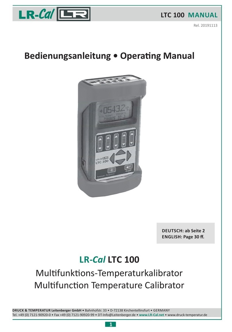
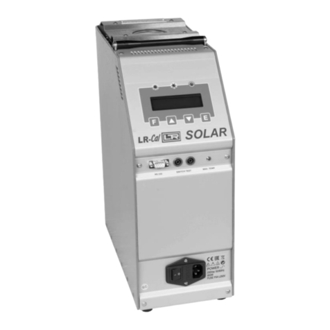
DRUCK & TEMPERATUR Leitenberger LR-Cal Pyros Basic 375 User manual

DRUCK & TEMPERATUR Leitenberger GmbH: Manu Basic 375 + PYROS Basical PYROS 650LR- LR-Cal Cal Page 1 of 24
Operang Manual
Dry Block Temperature Calibrator
LR- LR-Cal CalPYROS Basic 375 + PYROS Basic 650
DRUCK & TEMPERATUR Leitenberger GmbH
Bahnhofstr. 33
72138 Kirchentellinsfurt
GERMANY
Tel.: +49-7121-90920-0
Fax: +49-7121-90920-99
www.LR-Cal.net
E-Mail: DT-Export@Leitenberger.de

DRUCK & TEMPERATUR Leitenberger GmbH: Page 2 of 24
INDEX
1 - INTRO DUCTION ............................................................................................................4
1.1 - Purpose and summary of instru cons .......................................................................4
2 - SCOPE OF SUPPL Y......................................................................................................5
2.1 - Name ........: ............................................................................................................ ...........5
2.2 - Technical dat a: .................... .....................................................................................5........
2.3 - Service (funcon) :.....................................................................................................6
2.4 - Q uanty: .................................................................................. .................................... ...6
2.5 - Cons tructor: ......................................................................................................... ........... .6
2.6 - N° of correspond ent catalogue sheet:............................... ........................................6......
2.7 - List of first equipment accessories:............................................................... ............6.......
3 - GENERAL RE COMMENDATION S.................................................................. .............. 7....
4 - SAFETY IN STRUCTIONS............................................................................ ..................9....
5 - PREPARATION OF OPERATION ................................................................... ..................10
5.1 - Installaon ..................................................................................................... ............... .10
5.1.1 - Removal of packaging ............................................................................. .......10...
5.1.2 - Posioning the calibrator ......................................... ......................................10..
5.1.3 – Supply: 115 or 230V switchable ...................................... ..............................10.
6 - OPERATION PROCEDURE ................................................... .....................................12..
6.1 - Operaon descripon.......................................................... ....................................12.......
6.2 - Descripon of instrument .................................................. ...................................... 12......
6.2.1 - Thermo regulator ........................................................ ....................................12...
6.2.2 - Main switch .................................................................. ...................................12....
6.2.3 - Heang resistance .................................................. ........................................12...
6.2.4 - Equalising block ...................................................... .......................................12...
6.2.5 - Temperature sensors .............................................. .......................................13..
6.2.6 - Safety thermostat ..................................................... ......................................13...
6.3 - Start-up instrucons.............................................................. ..................................13.......
6.4 - Use of the funcon............................................................... ................................... 14......
6.5 - Re-calibraon methods.......................................................... .................................15.......
7 - MAINTENANCE INSTRUCT IONS ............................................ ...................................16...
7.1 - Roune inspecons instrucons ...................................... .......................................16..
8 - SEQUENCE OF MAINTENANCE ........................................... .................................... 16....
9 - TYPICAL FAULTS .....................................................................................................17
10 - APPENDI CES ................................................................... .........................................18..
10.1 -Thermoregulator ............................................................. .......................................18......
10.2 - Spare parts list ................. .. .................................................... ....................................19
10.3 - Declaraon of conformity and check report ..................... .....................................20.....
10.4 - Drawing and wiring diagram .............................................. ...................................21......
Manu Basic 375 + PYROS Basical PYROS 650LR- LR-Cal Cal

DRUCK & TEMPERATUR Leitenberger GmbH: Page 3 of 24
WARNING
Hazardous voltages are present in this electrical equipment during operaon.
Non-observance of the safety instrucon can result in severe personal injury or property
damage.
Only qualified personnel should work on or around this equipment aer becoming familiar
with all warnings, safety noces, and maintenance procedures contained herein.
Only qualified personnel or our personnel should work on this equipment for maintenance
operaon.
The successful and safe operaon of this equipment is dependant on proper handing,
operaon and maintenance.
Electrical and electronic equipments with this symbol can not be thrown away in public
dump sites. According to the EU direcve 2002/96/EC, the European users of electrical
and electronic equipment have the opportunity to return to the distributor or manufacturer
used equipment purchasing a new equipment. The illegal disposal of electrical and
electronic equipments is punished by pecuniary administrave sancon .
SYMBOLS BEING USED IN THIS MANUAL OR ON THE INSTRUMENT
CAUTION: HOT SURFACE OR PART
CAUTION: REFER TO ACCOMPANING DOCUMENTS
CAUTIONS: RISK OF ELECTRIC SHOCK
N.B:
In this manual: where not specified, the numbers in parentheses make reference to the annexed
drawing.
Manu Basic 375 + PYROS Basical PYROS 650LR- LR-Cal Cal

DRUCK & TEMPERATUR Leitenberger GmbH: Page 4 of 24
1 - INTRODUCTION
1.1 - Purpose and summary of instrucons
This manual contains the use and maintenance instrucons valid for the following equipment:
Portable Temperature Calibrator model: LR- LR-Cal CalPYROS Basic 375 and PYROS Basic 650
The instructions reported in this manual, for the above-menoned equipment, are those relevant to:
Start-up preparaon
Operaon descripon
Using of the equipment
Re-calibraon procedure
Prevenve maintenance
Typical faults and their remedies
Users must observe all the usual safety rules out in this manual for own security and to avoid
equipment failure.
Manu Basic 375 + PYROS Basical PYROS 650LR- LR-Cal Cal

DRUCK & TEMPERATUR Leitenberger GmbH: Page 5 of 24
2 - SCOPE OF SUPPLY
2.1 - Name:
Portable Temperature Calibrator, complete of accessories as listed (reference to
paragraph 2.7).
2.2 - Technical data:
Environmental range: temperature +5 ÷ +45°C, R.H. max. 95%.
Standard model with bronze block
Probe : Tc
Package size : 415x570xh235mm
Weight with package : 13,5 kg
Structure in flanged plate with handle
Microprocessor operated temperature regulator.
Manual rese ng safety thermostat.
Switch test.
Internal oven in stainless steel.
Electronic control components thermally insulated.
Double way Forced air-cooling system.
Removable upper protecon grid.
Total absence of environmentally harmful cooling liquids.
Socket with main cable and protecon fuses.
;Electromagnec compability : Emission EN50081-1 Immunity EN50082-2
Manu Basic 375 + PYROS Basical PYROS 650LR- LR-Cal Cal
TECHNICAL DATA PYROS Basic 650
Temperature range +35…+650°C
Mean heang me 35 min.
(incl. stabilizaon) (+50…+650°C)
Mean cooling me 60 min.
(incl. stabilizaon) (+650…+100°C)
Axial temperature a) ±0.10°C at +50°C b) ±0.02°C at +50°C ±0.13°C at +250°C
uniformity a) ±0.20°C at +150°C b) ±0.05°C at +150°C ±0.15°C at +450°C
(at 40 mm depth) a) ±0.30°C at +375°C b) ±0.15°C at +375°C ±0.35°C at +650°C
uniformity
between both n/a
blocks (at 40 mm depth)
Radial temperature a) ±0.10°C at +50°C b) ±0.05°C at +50°C
unifomity a) ±0.15°C at +150°C b) ±0.10°C at +150°C ±0.22°C
(at 40 mm depth) a) ±0.20°C at +375°C b) ±0.15°C at +375°C
Usable inseron depth
in the metal block
Hole diameter 26 mm
Display accuracy
(±1 digit)
Stability a) ±0.15°C b) ±0.10°C ±0.30°C
Display resoluon 0.1°C
Temperature units °C / °F
Ovewr temperature cut out ja
Switch test 5 VDC
Dimension 130 x 260 x 280 mm
Weight 6.0 kg
Power supply (±10%) 115/230 VAC
Power consumpon 600W
All values are valid at ambient temperature +20°C.
Diameter of the sensor, used for tesng the performances:
LR-Cal PYROS Basic 375: Pt 100 a) diameter 6 mm; b) diameter 3 mm
LR-Cal PYROS Basic 650: Pt 100 diameter 4,5 mm
±0.90°C
600W
150 mm
°C / °F
ja
5VDC
130 x 260 x 280 mm
5.4 kg
115/230 VAC
(+375…+100°C)
PYROS Basic 375
+30…+375°C
20 min.
(+30…+375°C)
40 min.
n/a
26 mm
±0.25°C at +150°C
±0.50°C at +375°C
0.1°C
150 mm

DRUCK & TEMPERATUR Leitenberger GmbH: Page 6 of 24
2.3 - Service (funcon):
The portable temperature calibrator /PYROS Basic 375 PYROS Basic 650LR- LR-Cal Cal has been designed for:
Control andcalibraon of temperature sensors, in the laboratory, on board and in the field, in
conformity with ISO 9000 standard.
Calibraon of thermostats with light indicaon when electric contact close.
Thermal test on materials.
The calibrator has been designed to reduce the EMC effect in accordance with the harmonised
regulaon for residenal, commercial, light industry and heavy industry.
2.4 - Quanty:
1 piece.
2.5 - Constructor:
DRUCK & TEMPERATUR Leitenberger GmbH
Bahnhofstr. 33, D-72138 Kirchentellinsfurt, GERMANY. www. - al.LR C net
2.6 - N° of correspondent catalogue sheet:
PYROS Basic 375 - PYROS Basic 650
2.7 - List of first equipment accessories:
Cerficaon: all the instruments are supplied with final tesng, stability and accuracy cerficaon
trace internaonalable to standards.
Manu Basic 375 + PYROS Basical PYROS 650LR- LR-Cal Cal
Standard scope of delivery Order-Code Order-Code
PYROS Basic 375 PYROS-BASIC-375 PYROS Basic 650 PYROS-BASIC-650
• Dry block calibrator • Dry block calibrator
• Tweezers for insert removing • Tweezers for insert removing
• Mains power cable • Mains power cable
• Kit of spare fuses • Kit of spare fuses
• Connecon cables for • Connecon cables for
thermostat tesng thermostat tesng
• Operang manual • Operang manual
• Test cerficate • Test cerficate
• 1 insert with 4 holes • 1 insert with 4 holes
3.2 + 4.8 + 6.4 + 11.1 mm 3.2 + 5.0 + 7.0 + 10.5 mm
Oponal accessories
for PYROS Basic 375 Order-Code for PYROS Basic 650 Order-Code
1 blank insert PYROS-375-INS-0 1 blank insert PYROS-650-INS-0
1 insert with 4 holes 1 insert with 2 holes
3.2 + 4.8 + 6.4 + 11.1 mm 6.5 + 12.7 mm
1 insert with 2 holes 1 insert with 3 holes
6.4 + 12.7 mm 4.5 + 6.5 + 10.5 mm
1 so bag PYROS-TASCHE 1 insert with 4 holes
1 plasc marine case IP67 PYROS-KOFFER 3.2 + 5.0 + 7.0 + 10.5 mm
1 insert with 4 holes
3.2 + 5.0 + 6.5 + 10.5 mm
1 insert with 1 hole 15.7 mm PYROS-650-INS-1
1 insert with 1 hole 17.5 mm PYROS-650-INS-1S
1 so bag PYROS-TASCHE
1 plasc marine case IP67 PYROS-KOFFER
PYROS-650-INS-4
PYROS-650-INS-4S
PYROS-375-INS-4
PYROS-375-INS-2
PYROS-650-INS-2
PYROS-650-INS-3S

DRUCK & TEMPERATUR Leitenberger GmbH: Page 7 of 24
3 - GENERAL RECOMMENDATIONS
ÎATTENTION
The configuraon of the instrument is protected by a password and by the protecon code.
To accede at the configuraon parameters reset the password & the protecon code:
contact our technical office.
Don’t change these parameters to avoid malfuncon or breaking of the calibrator with risks
of serious personal injury.
- Posion of the probe:
To obtain the best result, follow the advises:
Measure the diameter of the probe being checked.
The diameter of the hole in the calibraon block must be higher than the diameter of the probe;
following this measure:
◊0,5mm for ø4,5÷8mm probes (max. operave range 600°C)
◊0,7mm for ø8÷12mm probes (max. operave range 600°C)
◊1 mm for ø12÷17mm probes (max. operave range 600°C)
◊Reduce this tolerance for max. operave range lower then 300°C
If this is not possible, use the reducon wells with the above-menoned tolerances (fig.1).
Avoid using holes which are too accurate and do not force the probes into the block.
Put the probe or the insert in the block only at ambient temperature; for reducon insert using
the tweezers.
Insert the probe up to the bo om of the block: the sensive element is in the opmal calibraon
zone (fig. 2).
Calibraon with a reference: take care to posion the two probes, the standard one and the
calibraon one, at the same dept and as close together as possible (fig. 3).
Always verify the range of the probes to be calibrated before using; the maximum temperature
of the probes should be higher then the temperature of the block otherwise the probe could
break.
Fig.1 Fig.3Fig.2
Manu Basic 375 + PYROS Basical PYROS 650LR- LR-Cal Cal

DRUCK & TEMPERATUR Leitenberger GmbH: Page 8 of 24
- Advises:
The me the probes takes to reach the Set point is much more higher as the difference in
diameter from the probes and the holes is bigger.
Do not insert the probe when the instrument has already reached the set temperature; thermal
shock causes instability and breakage of the sensive element.
For the calibraon of temperature transducer with special execuon, call our technical office and
ask for equaliser block with special drillings.
REMEMBER TO SET UP AMBIENT TEMPERATURE AND LEAVE COOLING DOWN
BEFORE SWITCHING OFF THE CALIBRATOR
Manu Basic 375 + PYROS Basical PYROS 650LR- LR-Cal Cal

DRUCK & TEMPERATUR Leitenberger GmbH: Page 9 of 24
4 - SAFETY INSTRUCTIONS
ATTENTION:
Due to the fact that the calibrator is a portable instrument to be used in the field, it is
very important to ensure that the socket has been earthen correctly when connecng it
to the electricity supply.
Carry out the maintenance and repair operaon only with the equipment at ambient
temperature and disconnect the electrical cable.
During the use of the calibrator, the upper protecon grid may overheat.
Don’t touch the probe to calibrate when it’s in the block.
Aer using wait for the stabilisaon at ambient temperature before returning the
calibrator to its carrying case. Don’t switch off the calibrator when it works at high
temperature because the protecon grid and the carpentry may overheat.
Never put any type of liquid inside the block.
Don’t change absolutely the configuraon parameters.
Don’t put anything on the top of the calibrator.
Don’t put fuel object near the calibrator.
...... use common sense any me.
The equipment adopt the following devices to protect operaon from hazard:
The thermo regulator recognizes an eventual break of the temperature sensor (9) and
disconnect the heang.
Max. temperature safety thermostat (11) to disconnect the heang system.
Protecon grid to avoid any contact with the internal oven.
Protecon fuses (3)
Ground conductor.
Manu Basic 375 + PYROS Basical PYROS 650LR- LR-Cal Cal

DRUCK & TEMPERATUR Leitenberger GmbH: Page 10 of 24
5 - PREPARATION OF OPERATION
Remove the calibrator from the packaging and place it on a flat surface.
Make sure that the instrument has been correctly earthen.
Supply the oven with line 230V, 50Hz (3,15A) or 115 V (6,3A) + earth, 3,15A (6.3A for
115V).
Before start the calibraon read with a enon the instrucon manual, specially the
paragraph 3: - General recommendaon -.
5.1 - Installaon
5.1.1 - Removal of packaging
The calibrator is equipped with packaging suitable for transport and tradional shipping systems.
Any damage caused during transport must be nofied immediately to the carrier and a claim must
be made.
5.1.2 - Posioning the calibrator
Posion the calibrator in a safe clean place; leave enough space around the calibrator to allow the
air to circulate well.
**DANGER : The calibrator is suitable for operang at high temperatures with the consequent
danger of fire. Keep it away from any type of inflammable materials and never put
any type of liquid inside the block (reference to paragraph 4).
*WARNING : To avoid any smell in the room it is be er to switch on the calibrator outside the
room for the first me
5.1.3 – Supply: 115 or 230V switchable
The calibrator runs on a voltage of 230 or 115Vac, 50/60Hz. The equipment is configured
for the 230V power supply or for the voltage indicated by the voltage switch(13). If it is
necessary to change the tension, for example from 230 to 115V:
◊unscrew the two screws of the plate 13
◊move the switch 13, with a screwdriver, in order to read 115
◊screw the plate back, in the opposite direcon, so that you read the inscripon 115V.
A 2.5mt. cable is supplied with the calibrator fi ed with 2 conductors plus earth (1mm 2).
Make sure that the plant is earthen correctly before switching the instrument on.
Manu Basic 375 + PYROS Basical PYROS 650LR- LR-Cal Cal

DRUCK & TEMPERATUR Leitenberger GmbH: Page 11 of 24
COMMANDS LIST
POS. DESCRIPTION
1 SUPPLY SOCKET
2MAINSWITCH
3PROTECTIONFUSES
4SWITCHTEST
5 SWITCH TEST ON/OFF LIGHT
6 TEMPERATURE REGULATOR
13 VOLTAGE SWITCH/INDICATOR
4
5
6
2
3
1
13
Manu Basic 375 + PYROS Basical PYROS 650LR- LR-Cal Cal

DRUCK & TEMPERATUR Leitenberger GmbH: Page 12 of 24
6 - OPERATION PROCEDURE
6.1 - Operaon descripon
The PYROS-650 calibrator consist of a metal dry well with one hole of 26x150mm into which, the
inserts available for almost any sensor size to be calibrated, are inserted.
A heater element heats the block and an electronic µcontroller with stac relay output checks and
regulates the temperature.
A fan mounted in the central side generates a constant airflow that reduces the temperature of the
case.
6.2 - Descripon of instrument
6.2.1 - Thermo regulator
The thermo regulator (6) is a PID microprocesso 375/r, which can be set from 0 to 650°C. The display
indicates the temperature and the Set point (ref to item 10.1).
DISPLAY: indicaon of the temperature measured inside the block, set point selected and se ng
parameters .
56 KEY: used to increment (decrement) any numerical parameter. The increment (decrement)
speed is proporonal to the me the key remains depressed.
P KEY: allow access to the various parameters, access to the various phases of configuraon.
U KEY: allow access to the various group of parameters, access to the various phases of
configuraon or confirm the Set point.
6.2.2 - Main switch
The main switch (2) is on the rear of the instrument; it is fi ed with a socket for the voltage cable, a
main switch and two fuses as for the following table:
MODELS V230 V110/115
PYROS-375/650 3,15A 6,3 A
Note: use only fuses F. 5x20mm. All the electrical part is found below the main switch.
6.2.3 - Heang resistance
The resistance is stainless steel made; the max. power is 600W. and it can reach temperatures
approaching 375°C/650°C.
Bear in mind, however, that constant use at extreme temperatures reduces the life of the
resistance itself. Limit the number of hours at which the resistance is used at maximum
temperatures to the me required by the calibrator in order to prolong the life of the
resistance.
6.2.4 - Equalising block
The metal equalising block has an hole of 26mm where introduce the inserts far almost any sensor
size.
The funcon of this block is to make uniform the temperature on calibraon zone.
If you want to fit the calibrator with an insert wi th different holes we recommend to read the item 3.
This will avoid any unfortunate problems, which might arise if the wrong tolerances are used
Manu Basic 375 + PYROS Basical PYROS 650LR- LR-Cal Cal

DRUCK & TEMPERATUR Leitenberger GmbH: Page 13 of 24
6.2.5 - Temperature sensors
The temperature sensor used for the reading and thermoregulaon is a Thermocouple probe; the
probe is inserted directly into the equalising block so as to supply a temperature value close to the
real value in the block.
6.2.6 - Safety thermostat
The calibrator is supplied with a max. temperature safety thermostat with manual reset (11) that
disconnect the heang system.
In case the thermostat intervenes:
◊Waing the cooling of calibrator: the temperature must decrease at least 60÷80°C respect
to maximum set point (standard posion).
◊Switch off the calibrator then switch on again a few second later on.
◊If the problem persists: disconnect the electrical cable to the oven and proceeding to repair
of eventual faults (reference to paragraph 4). Consulng chapter 9 - typical faults - for any
problems on the thermostat.
N. B: the thermostat mounted on standard ovens has been calibrated in factory to intervene at
665°C±10°C.
6.3 - Start-up instrucons
ATTENTION:
The calibrator can only be used correctly if the user has a good knowledge of its basics.
Before starng with the calibraon following the installaon procedures (paragraph 5); read the
instrucon on paragraph 3 & 4.
To calibrate the probe it is possible to follow two ways: calibraon with internal indicator (6), or
calibraon with external reference.
A) Calibraon with the internal indicator):
Make reference to the temperature value of the display (6).
It is opportune to refer the value to the test report to compensate the error of the display.
B) Calibraon with external reference:
Make reference to the temperature value of the external standard instrument.
Put the sensive elements of the probes near and at the same dept (reference to fig. 1-2-3-5).
A
B
Manu Basic 375 + PYROS Basical PYROS 650LR- LR-Cal Cal

DRUCK & TEMPERATUR Leitenberger GmbH: Page 14 of 24
Before any calibraon follow the general recommendaon:
Switch on the calibraon with the main switch (2); waing for the end of self-test procedure.
Put the probe to check into the equaliser block: reference to chapter 3. (fig 1-2-3).
Set the required temperature value on the thermo regulator (reference to paragraph 10.1):
◊Press 6or P to adjust the Set Point.
◊Press the 5key to increment the set point value.
◊Press the 6key to decrement the set point value.
◊Push U for 3” or wait for 10” to confirm the Set Point.
If the temperature is lower than the Set Point the two red leds are on.
Wait for the stabilisaon of the oven before start with the calibraon.
For different calibraon point, regulate the set point at the new temperature and wait for the
stabilisaon.
The temperature indicated by the display must not be considered as a reference temperature
but only as a general indicaon of the temperature inside the block.
We suggest to insert one primary standard with SIT cerficate in the block; compare the
measure with the values indicated by the stan dard. Don't ever use the primary standard: it's
possible to calibrate the instrument to more significant points, comparing the displayed
temperature with that temperature of standard.
ATTENTION
At the end of the calibraon DO NOT remove the probe if it is sll at high temperature.
Always allow the calibrator to cool off with the probe sll inserted in order to avoid
thermal shock to the probe itself and harm to people or things.
Before returning the calibrator to its case make sure that the temperature of the block is
almost the same as ambient temperature.
-Cooling
To reduce the oven’s temperature, change the set point to 0°C and wait for the natural cooling.
6.4 - Use of the funcon
-Switchtest
You can test the operang point of the thermostats by the 'SWITCH TEST' funcon (4).
Put the thermostat in the most suitable hole of the block (see the note in paragraph 3).
Connect the terminals of the thermostat to the socket (4).
Switch on the calibrator.
Set the test temperature 5% lower to the operang temperature of the thermostat then increase
the Set Point one or two °C each me in order to switch Off/on the thermostat, the lamp (5) will
come on or Off when the thermostat electric contact works.
Set the test temperature lower to the operang temperature + the differenal of the thermostat,
the lamp (5) will come Off/on when the thermostat electric contact works.
- Configuraon of the rate for posive Set point change(rump up):
Press and hold the “P” bu on for about 3 seconds to enter the Password.
Manu Basic 375 + PYROS Basical PYROS 650LR- LR-Cal Cal

DRUCK & TEMPERATUR Leitenberger GmbH: Page 15 of 24
Enter the pass. ‘1020’ using the arrows and press the “P” bu on again (if the password is
entered correctly, the display will show Sp 1, if not, the instrument returns to the condion it was
in previously).
Use the arrows to set Sp 1 and press “P”.
The display will show Sp.u. The parameter has a range of 0.01 to 100.00(inF) [unit/min.]. (For
example the value 1.00 is about one degree Celsius for minute) Use the arrows to set Sp.u and
press “P”.
The display will show Sp.d. the display will show inF The parameter has a range of 0.01 to
100.00(inF) [unit/min.]. Do not modify the value and press P.
Press and hold the “U” bu on for about 5 seconds to exit from ramp funcon. THIS RAMP IS
NOW CONFIGURED FOR ALL THE SETPOINTS.
If you wish to disable this ramp, repeat this procedure from the start to re-access configuraon
SP.u parameter to inF then push U to exit.
During the rise in temperature with the ramp the lower display will change the value with the rate
you have set. The turning on or off of the lamp (5) idenfies the moment of triggering, at this
point note the value of the display (6) before se ng a lower temperature at the triggering point
of the thermostat, considering the differenal. During the fall in temperature check the
thermostat has intervened with the turning off or on of the lamp (5) and note the value of the
display (6), if the value set is not sufficient set a lower temperature. The two temperature values
recorded are equivalent to the trigger points of the thermostat, if necessary repeat the test two
or more mes to verify the repeatability of the thermostat.
6.5 - Re-calibraon methods
To have instrument always efficient is opportune to re-calibrate it periodically.
Frequency of re-calibraon is depending to the use of instrument; however we suggest to re-
calibrate instrument every year.
To re-calibrate instrument is necessary to have a standard temperature instrument with SIT
cerficaon.
CALIBRATION OF THE REGULATOR:
To calibrate the Pyros it is necessary a standard probe.
The parameters that allows to calibrate the Pyros650 are the following :
Par. Descripon
130 A.L.P Adjust low point
131 A.L.o Adjust low offset
132 A.H.P Adjust high point
133 A.H.o Adjust high offset
Press and hold the “P” bu on for about 3 seconds enter the Password.
Enter the pass. ‘1030’ using the arrows and press the “P” bu on again (if the password is
entered correctly, the display will show InP, if not, the instrument returns to the condion it was
in previously).
By U bu on select the group of CAL parameter.
By P bu on select A.L.P.
Use the arrows to set A.L.o. and press “P”.
Use the arrows to set A.H.P. and press “P”.
Use the arrows to set A.H.o. and press “P”.
Press and hold the “U” bu on for about 5 seconds to exit from Calibraon.
Manu Basic 375 + PYROS Basical PYROS 650LR- LR-Cal Cal

DRUCK & TEMPERATUR Leitenberger GmbH: Page 16 of 24
For example:
If you want to calibrate the Pyros to the values 50 and 500°C proceed in this steps:
insert a standard thermometer in the oven and set the set point of 50°C and
wait unl the oven is stable then read the value of the display of Pyros and the value of the
standard probe.
50= A.L.P value of the display of the Pyros.
48= value of the standard thermometer
Set a negave value of -2 to the value of the display in order to indicate the value of the Standard
reference.
Set the set point to 500°C and
wait unl the oven is stable then read the value of the display of Pyros :
500= A.H.P value of the display of the Pyros.
497= value of the standard thermometer
Set a negave value of -3 to the value of the display in order to indicate the value of the Standard
reference.
Set a Posive or negave Offset that is simply added to the value read by the probe before
visualizaon.
Set this values to correct the instrument
Par. Descripon value
130 A.L.P Adjust low point 50
131 A.L.o Adjust low offset -2
132 A.H.P Adjust high point 500
133 A.H.o Adjust high offset -3
Press and hold the “U” bu on for about 5 seconds to exit from Calibraon.
Now the calibraon is completed.
7 - MAINTENANCE INSTRUCTIONS
7.1 - Roune inspecons instrucons
Check that the holes of the calibrator are cleaned, any liquid or oil inside the hole could make
oxides or dirty during the use at high temperature.
Check once a year the calibraon date. Frequency of calibraon is depending to the use of
instrument; however we suggest to calibrate the instrument every year.
8 - SEQUENCE OF MAINTENANCE
Not applicable
Manu Basic 375 + PYROS Basical PYROS 650LR- LR-Cal Cal

DRUCK & TEMPERATUR Leitenberger GmbH: Page 17 of 24
9 - TYPICAL FAULTS
Before carrying out these operaons the instrument must be disconnect from the
electricity supply and the equaliser block must be at ambient temperature.
N° FAULT DESCRIPTION FAULTY COMPONENT OR
FUNCTION
METHOD FOR REMOVAL
1 The calibrator does not work
when the power cable is
connected and the main
switch is turned on.
- The fuse (3) is cut off.
- The power cable is cut off.
- The main switch is faulty.
- Replace the fuses.
- Replace the power cable with a
similar one.
- Replace the cup socket (1-3)
2 The fuses (3) are triggered
when the power cable is
connected and the main
switch is turned on.
- The fuse is wrong - Check the value of the fuse(ref.
to item 6.2.2)
3 The control panel is working
properly but the temperature
does not increase.
- The stac relay (10) is faulty.
- The safety thermostat (11) has
been triggered.
- The thermo-regular is faulty
- Replace the stac relay.
- Wait the cooling; the temperature
must decrease at least 60÷80°C
andswitchofftoresetthealarm
Ref 6.2.6.
- Replace the thermo-regulator.
4 The display indicates a
different temperature from the
one measured in the block.
- The probe (9) is faulty. - Replace the probe.
5 The temperature does not
stop at the value of the point,
which has been set.
- The stac relay (10) is faulty. - Replace the stac relay.
6 The temperature does not
decrease to the set value as
quickly as it should.
- The thermo-regulator (6) is
faulty.
- The cooling fan (7) is faulty.
- Replace the thermo-regulator.
- Replace the fancoil.
7 The display show '-----' or
‘uuuu’ or ‘oooo’
- The control probe N.9 is faulty
or in short circuit
- The thermo-regulator (6) is
faulty.
-Replacetheprobe.
- Replace the thermo-regulator.
8 The display indicates ErEP - Eprom faulty - Push the P bu on of the thermo-
regulator
Manu Basic 375 + PYROS Basical PYROS 650LR- LR-Cal Cal

DRUCK & TEMPERATUR Leitenberger GmbH: Page 18 of 24
10 - APPENDICES
10.1 -Thermoregulator
Descripon of the funcons
DISPLAY
It normally indicates the process
value
UandPareusedtoaccessthe
programming parameters and
to confirm selecon
OUT1 = indicates that the heang is ON
OUT2 = indicates that the fan coil is ON at
low speed
This is used to increase the
values to be set and to select
the parameters
This is used to decrease the
values to be set and to select
the parameters
It normally indicates the
acve Set value
Manu Basic 375 + PYROS Basical PYROS 650LR- LR-Cal Cal

DRUCK & TEMPERATUR Leitenberger GmbH: Page 19 of 24
10.2 - Spare parts list PYROS-650LR-Cal
(Reference numbers referring to the enclosed drawings)
1-3 CUP SOCKET 3SCH28366
3 FUSES 5x20 3,15A for 230V
5x20 6,3A for 115V
4SWITCHTESTCO
NNECTION 3B&BPAN10A
5 SWITCH TEST LAMP 3RSC3693970
6 THERMO REGULATOR 4TCNK39HCOR
7 12V FAN COIL 3PPS3312M
8 SAFETY THERMOCOUPLE 3D2417
9 REGULATION THERMOCOUPLE 3D1653
10 25A STATIC SWITCH 3GFR GQ2548D11
11 SAFETY THERMOSTAT 4ED10085
12 RESISTOR 3D2906
13 230V / 115V SWITCH 3RSC321290
ELECTRIC POWER CABLE 3NEP5942AW
TWEEZER FOR THE INSERTS 2DC535-000
SWITCH TEST CABLES 3MRC372124 +
3MRC212320
10.3 - Declaraon of conformity and check report
The declaraon of conformity CE is at the end of the manual; the test report is included with the
calibrator.
10.4 - Drawing and wiring diagram
The drawings are at the end of the manual.
Manu Basic 375 + PYROS Basical PYROS 650LR- LR-Cal Cal

DRUCK & TEMPERATUR Leitenberger GmbH: Page 20 of 24
"Declaraon of conformity"
DRUCK & TEMPERATUR Leitenberger GmbH, Bahnhofstr. 33, 72138 Kirchentellinsfurt,
GERMANY
Declares that the: THERMOSTATIC CALIBRATOR PYROS-375 / PYROS-650LR-Cal
is conforms with the requirements of the following European direcve:
Low voltage direcve 73/23/EEC amended by 93/68/EEC and by 2006/95/CE
EMC direcve EMC 2004/108/CE
and that it has been designed in accordance with the following harmonized regulaon:
EN 50081-1 light industrial emission.
EN 50082-1 industry immunity.
EN 6101-1 safety requirements for electrical equipment
The conformity with the above-menoned requirements is cerfied by affixing the CE Mark on the
product.
DRUCK & TEMPERATUR Leitenberger GmbH
Gernot Coulon (C.E.O.)
October 2 nd., 2010
Manu Basic 375 + PYROS Basical PYROS 650LR- LR-Cal Cal
This manual suits for next models
1
Table of contents
Other DRUCK & TEMPERATUR Leitenberger Measuring Instrument manuals
