[EN] English - K0463 Revision A Quick Reference 1
ATEX Approved Models
Introduction
These instructions detail the requirements for using the PV 62X-IS intrinsically safe pressure station in
a hazardous area. Read the whole publication before starting.
Application
PV 62X-IS pressure stations marked with certificate numbers Baseefa10ATEX0011X and
IECEx BAS 10.0003X are permitted for use in conjunction with DPI 620G-IS and PM 620-IS under the
“Intrinsic Safety Approval”.
Compatibility
The DPI 620G-IS series of pressure stations are not permitted for use in conjunction with DPI 620G or
PM 620.
Intrinsic Safety Approval
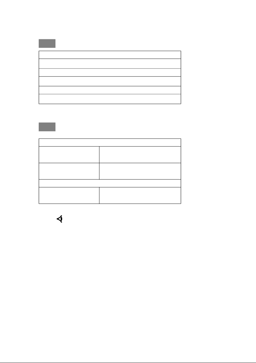
Marking details
Special Condition of Safe Use
• The lower ambient temperature is limited to -10°C.
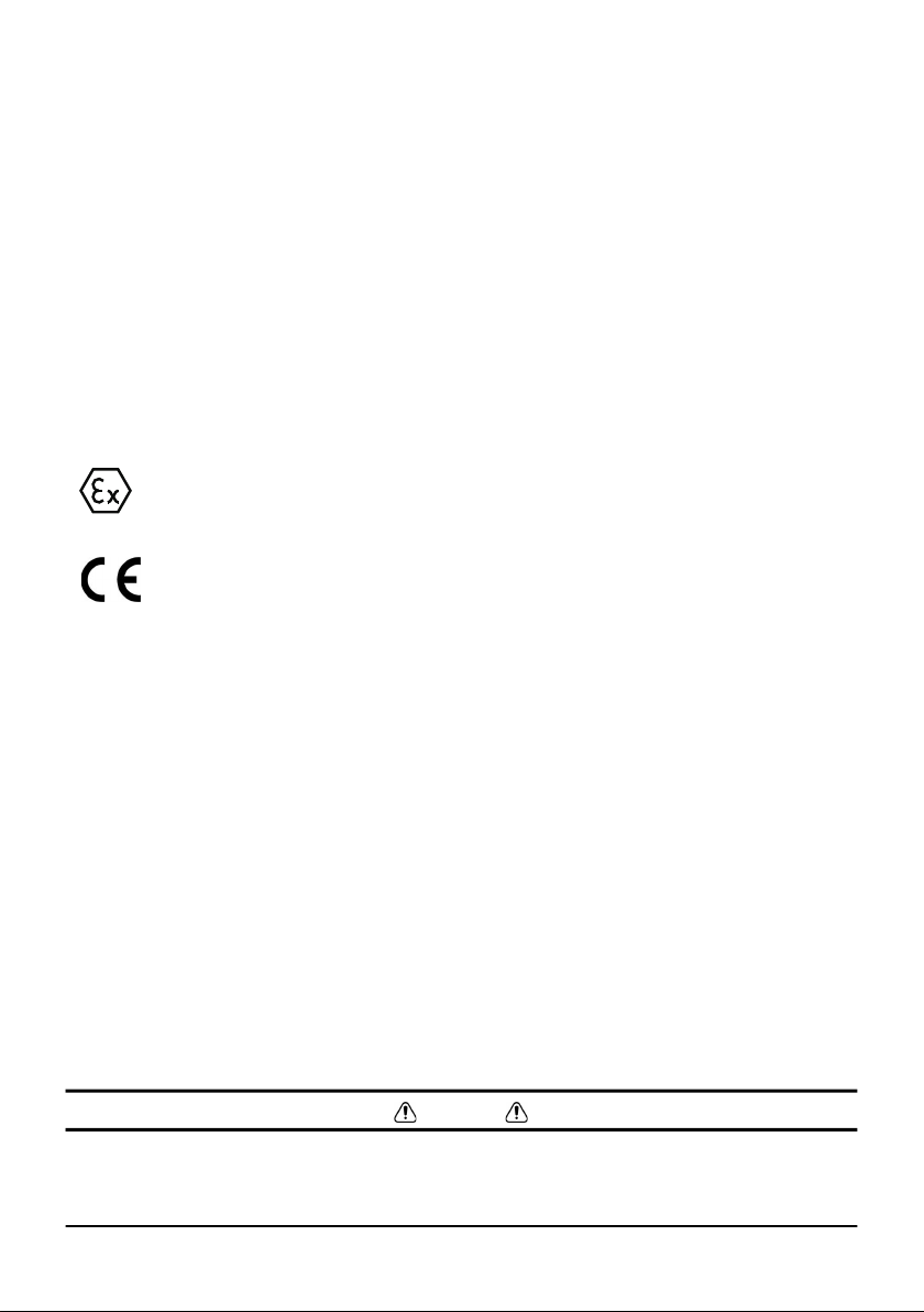
• When the PV 62X-IS Series Pressure Station is used with the DPI 620-IS Advanced Modular
Calibrator the position for the pressure transducer must be occupied with either a pressure
transducer or a dummy pressure transducer before connecting to the DPI 620-IS Advanced
Modular Calibrator and remains in position until the assembly is removed from the DPI 620-IS
Advanced Modular Calibrator.
IECEx Approvals
For the IECEx certificate (IECEx BAS 10.0003X), visit the IECEx website at: www.iecex.com
Declaration Requirements – EU Directive 2014/34/EU
This equipment is designed and manufactured to meet the essential health and safety requirements
not covered by EU Type Examination Certificate Baseefa10ATEX0011X when installed as detailed in
this guide.
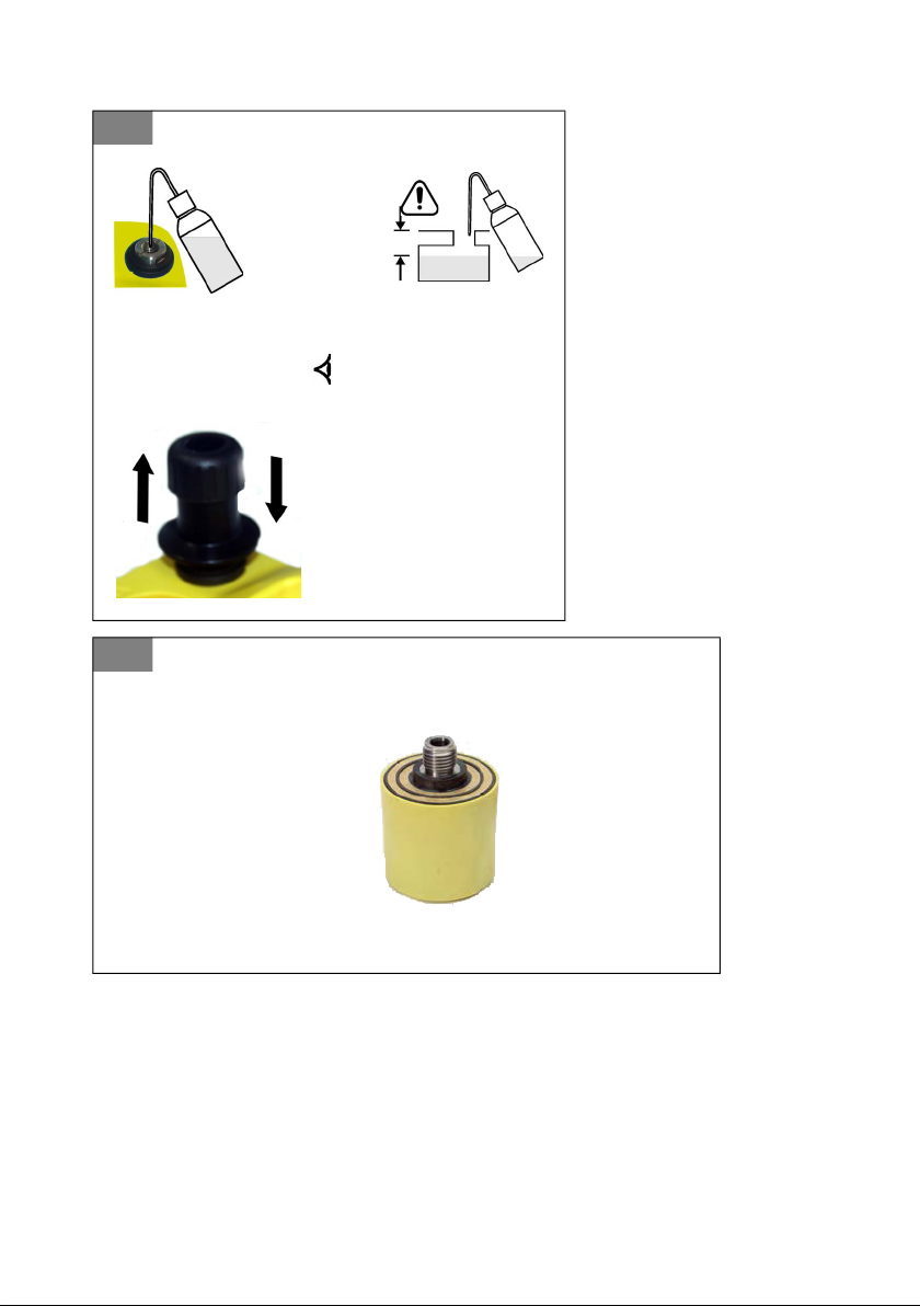
Installation
WARNING
• Do not use tools on the Pressure Station that might cause incendive sparks - this can cause
an explosion.
Baseefa10ATEX0011X.………………........................ ATEX Certificate number
II 2 G…………………...........…..…………… Equipment group & category
Ex ia IIC T4 Gb (-10°C ≤ Ta ≤ +40°C) .……............... Hazardous location markings
IECEx BAS 10.0003X…………………………............. IECEx Certificate number
####…………………………………….......... CE Mark
PV 62X-IS…............…………………….………..……. Specific apparatus type
(Pressure in bar or psi)…...........……………………… Maximum working pressure rating
Druck LTD. Groby, LE6 0FH, UK…………….........…. Manufacturer’s name and address
S/N *******……………………………………............… Serial number
DoM MMM YYYY……………………………...........…. Date of manufacture, Month and Year