Drummond MTL10 User manual

MTL10 & MTL20 TEST LAMPS
INSTRUCTION
MANUAL
MTL10 & MTL20
GENERAL SAFETY INFORMATION: Always read before proceeding.
Warning
These instructions contain both information and warnings that are necessary for
the safe operation and maintenance of this product. It is recommended that you
read the instructions carefully and ensure that the contents are fully understood.
Failure to understand and to comply with the warnings and instructions can result
in serious injury, damage or even death.
In order to avoid the danger of electrical shock, it is important that proper safety
measures are taken when working with voltages exceeding 50V AC RMS, or 120V
DC.
This product must only be used by a competent person capable of interpreting the
results under the conditions and for the purposes for which it has been
constructed. Particular attention should be paid to the Warnings, Precautions and
Technical Specifications. Always check the unit is in good working order before
use and that there are no signs of damage to it. Do not use if damaged.
Where applicable other safety measures such as use of protective gloves, goggles,
clothing etc. should be employed.
Please keep these instructions for future reference. Updated instructions and
product information are available at: www.martindale-electric.co.uk
REMEMBER: SAFETY IS NO ACCIDENT
MEANING OF SYMBOLS:
Equipment complies with relevant EU Directives
Caution - risk of danger & refer to instructions
End of life disposal of this equipment should be
in accordance with relevant EU Directives
Caution - risk of electric shock
Suitable for live working
ON/OFF (push button)
Thank you for buying one of our products. For safety and full
understanding of its benefits please read this manual before
use. Technical support is available from 01923 441717 and
support@martindale-electric.co.uk.
CONTENTS
1 Introduction 1
1.1 Inspection
1.2 Description 1
1.3 Accessories 1
2 Product Specific Safety Information 2
2.1 Precautions 2
3 Operation 5
3.1 Control Elements and Connections 5
3.2 Description of LED Indicators 5
3.3 Operating Duty Ratio 6
3.4 Proving Check 6
3.5 Testing for the Presence of Hazardous Live Voltage 7
3.6 Push Button Switches (MTL20 only) 8
3.7 Interference (Phantom) Voltage 8
4 Maintenance 10
4.1 Probe Replacement 10
4.2 Calibration 10
4.3 Cleaning 10
4.4 Repair & Service 11
4.5 Storage Conditions 11
5 Warranty 12
Specifications
1. INTRODUCTION
1.1 Inspection
Examine the shipping carton for any sign of damage. Inspect the
unit and any accessories for damage. If there is any damage then
consult your distributor immediately.
1.2 Description
The MTL10 and MTL20 test lamps are two-pole voltage indicators
for universal applications. They are designed to be used by skilled
persons in accordance with safe methods of work, and are
constructed in accordance with the applicable safety standards to
provide safe and reliable indication.
The MTL10 and MTL20 have the following features:
DC and AC Voltage tests up to 500V AC and 750V DC
Bright LED indication
Full voltage indication function without batteries
Ergonomic and robust housing
Probe tips comply with GS38
Measurement Category CAT IV 600V, CAT III 1000V
Constructed in compliance with EN 61243-3
IP64 rated environmental protection for internal electronics
1.3 Accessories (included)
2pc. Straight prod
1pc. L-shaped prod
Instructions
1

2. PRODUCT SPECIFIC SAFETY INFORMATION
Measurement Category III (CAT III) is applicable to test and
measuring equipment connected to the distribution part of the
building’s low-voltage MAINS installation.
Measurement Category IV (CAT IV) is applicable to test and
measuring equipment connected at the source of the building’s
low-voltage MAINS installation.
The specified measurement category means the voltage indicator
will be safe to the user if inadvertently connected to a voltage up to
1000V AC/DC to earth within a CAT III environment and 600V
AC/DC to earth within a CAT IV environment. It does not mean it
can be used to test for a voltage beyond its maximum specified
limits.
2.1 Precautions
This product has been designed with your safety in mind, but
please pay attention to the following warnings and cautions before
use.
Warning
The voltage indicator must only be used by a skilled and
competent person who is familiar with the relevant regulations, the
safety risks involved and the consequent normal safe working
practices.
Before each use the voltage indicator should be examined for
damage, cracks, cuts or scratches to the housing and cable. The
cable has black outer and contrasting inner insulation, to allow
damage to the cable to be easily identified. If there is any doubt
the voltage indicator should not be used.
2
Make sure the voltage indicator is dry, clean and free from dust,
grease and moisture while in use to avoid the danger from electric
shock due to surface leakage.
Before and after each use, the voltage indicator must be proven
using a suitable proving device or a known good voltage source.
Do not use the voltage indicator if any expected LED’s fail to
illuminate correctly during proving.
Testing for a voltage that exceeds the specified limits of the voltage
indicator may damage the voltage indicator and expose the
operator to a shock hazard. Always check the voltage indicator’s
specified limits before use.
If using the instrument in falling rain or damp conditions, the
operator must use additional protection to avoid the danger from
electric shock due to surface leakage. Select appropriate test
prods and secure with captive ring nuts. The L-shaped test prods
should be oriented in one of four directions using the square
location feature before it is secured.
When changing or adjusting the prods, ensure that both prods
have been disconnected from any source of power or other
equipment.
Always keep your fingers behind the finger guards. Never touch the
exposed metal prod tips.
The different indicating signals of the voltage detector (including
the ELV limit indication) are not to be used for measuring
purposes.
3
The voltage indicator must not be dismantled or modified in any
way by unauthorized persons. The safety of the voltage indicator
cannot be guaranteed under such circumstances and must not be
used.
Cautions
Avoid severe mechanical shock or vibration and extreme
temperature.
If the voltage indicator has been stored or transported in
temperatures outside its normal operating range it should be given
sufficient time to stabilise in the environment where it is to be used.
An acclimatisation time of at least 2 hours is required prior to
operation of the voltage indicator.
4
3. OPERATION
3.1 Control Elements and Connection
A - Instrument body B - LED indicator bands
C - Probe handle D - Straight prod
E - L shaped prod F - Switches (MTL20 only)
3.2 Description of LED Indicators
MTL10
MTL20
A
B
F
E
F
C
D
D
A
B
C
E
200V band
50V band
400V band
100V band
5

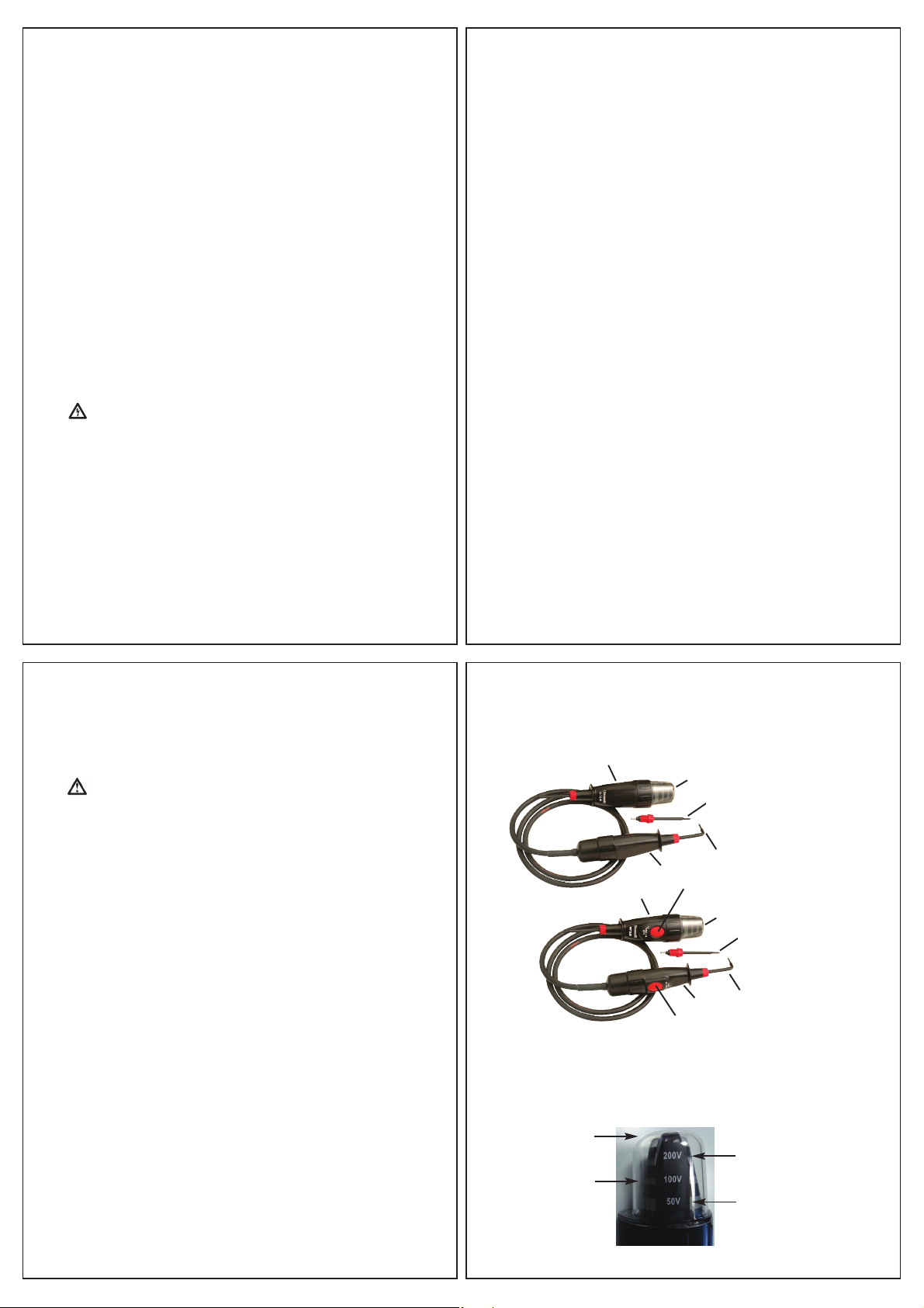
The magnitude of a voltage is indicated by the illumination of LED’s
in four separate bands around the top of the instrument body.
The nominal voltage thresholds of the indicator LED bands are 50V,
100V, 200V and 400V and are marked next to the relevant band.
The indicator LED bands will illuminate when the magnitude of the
voltage source is at a value approaching or greater than the
corresponding marked voltage. For example if the voltage source is
55V AC rms then only the 50V indicator LED band will illuminate, if
450V AC rms all four indicator LED bands will illuminate.
3.3 Operating Duty Ratio
The voltage indicator should be operated (ON) for a maximum
period of 30 seconds. This should be followed by a recovery period
(OFF) of 4 minutes.
The operating duty ratio is 8 to 1, so if the voltage indicator is only
ON for 2 seconds then the OFF period need only be 16 seconds.
3.4 Proving Check
Before and after use, verify the voltage indicator is functioning
correctly with a proving device (PD430 or PD440 is recommended),
or a known good voltage source. Do not use the voltage indicator if
any LED’s fail to illuminate correctly during proving.
Warning
If the proving device or voltage source exceeds the specified limits of
the voltage indicator the voltage indicator may be damaged and the
operator exposed to a shock hazard. Always check the specification
of the proving device or the voltage magnitude of the voltage source
before proceeding with a proving check.
6
The LED bands that illuminate during proving will depend on the
magnitude of the proving unit output or the voltage source.
For example if the voltage source is 230V AC rms then all LED
bands except the 400V LED band must illuminate. If a PD440 is
used then all LED bands must illuminate.
During this verification emphasis should also be place upon the
flexing of the voltage indicators cable along its length, and
particularly at the entry points to the hand held elements, to
confirm that the cable has not been fractured.
If using a PD430 or PD440 for proving, the press button switches
on the MTL20 can also be functionally checked. In this case when
both buttons are pressed simultaneously the 400V LED band will
cease to illuminate, indicating that the added load of the MTL20
has caused the output voltage of the PD unit to drop, thereby
proving the functionality of the switches and loading circuit.
3.5 Testing for the Presence of Hazardous Live Voltage
Warning
Hold the unit and test leads behind the finger guards in a manner
that will not obscure the voltage band indication LED’s. Never
touch the exposed metal test prods or any part of the instrument
forward of the finger guards while applied to hazardous voltages.
While taking all required safety precautions connect the test prods
across the test points where a voltage difference may be present.
The voltage level of any voltage present between the test points
will be indicated by the illumination of the relevant voltage indicator
LED bands.
7
3.6 Push Button Switches (MTL20 only)
The purpose of the push button switches on the MTL20 is to provide
additional load to the circuit under test where the presence of
interference (phantom) voltage may be suspected (see section 3.7).
Simultaneous depression of both switches (one on the probe
handle and one on the instrument body) introduces a load of
approximately 8.8kΩto the circuit being tested.
Note: Interference (phantom) voltages can rise again after the
push buttons are released. If a voltage indication re-appears on the
LED bands while the buttons are not pressed, there may be a
hazardous voltage that must be treated with caution.
3.7 Interference (Phantom) Voltage
It is possible for wiring that is ‘dead’ to indicate the apparent
presence of voltage at power frequency.
If wiring that is live is running in close proximity to the ‘dead’ wiring
being tested, there can be capacitive or inductive coupling between
the two, thereby causing interference (phantom) voltage.
Voltage indicators that draw a relatively low current when testing for
hazardous live voltage may not be able to suppress the
interference voltage to a low enough level so as not to indicate the
presence of a hazardous live voltage where there is not one.
The MTL10 & MTL20 will suppress typical levels of interference
voltage as defined by the test for interference voltage in the
standard EN 61243-3:2010.
Interference voltage that may be of a higher level than ‘typical’ may
not be suppressed by the MTL10 but should be suppressed by the
8
MTL20 when the push button switches are pressed to introduce a
higher load.
If there is any doubt as to whether a voltage indication is
hazardous live or interference, then alternative tests should be
performed.
9

4. MAINTENANCE
4.1 Probe Replacement
If the test prods become damaged they should be replaced.
Replacement prods are available as spare items:
Straight prod (DRUMTL2104)
L-shaped prod (DRUMTL2105)
Contact your local distributor or contact Martindale Electric on
01923 441717 or email sales@martindale-electric.co.uk.
4.2 Calibration
To maintain the integrity of indication, Martindale Electric
recommends that it is returned at least once a year to an approved
Calibration Laboratory for recalibration and certification.
Martindale Electric is pleased to offer you this service.
Please contact our Service Department for details.
Email: service@martindale-electric.co.uk Tel: 01923 650660
4.3 Cleaning
Warning
To reduce the risk of surface leakage, this instrument must be kept
in a clean condition.
Warning
Prior to cleaning, ensure that the instrument is disconnected from
any voltage source.
If the instrument is dirty it should be cleaned thoroughly using a
moist cloth. Particular attention should be paid to all areas forward
of the finger guards.
10
Do not use solvents, detergents or ionic cleaners, since these can
be conductive. After cleaning, any wet residue should be shaken
vigorously from the instrument. It should be dried thoroughly before
storage or further use.
4.4 Repair & Service
There are no serviceable parts in this unit. The MTL10 and MTL20
are sealed units and must not be opened for any reason.
4.5 Storage Conditions
The instrument should be kept in cool, dry conditions and not
subjected to shock, scratching or other damage, prolonged direct
harsh sunlight, extremes of temperature and in such a manner as
to preserve the working life of the unit. It is strongly advised that
the unit is not kept in a tool box where other tools may damage it.
11
12
5. WARRANTY AND LIMITATION OF LIABILITY
This Martindale product is warranted to be free from defects in
material and workmanship under normal use and service. The
warranty period is 2 years and begins on the date of receipt by the
end user. This warranty extends only to the original buyer or end-
user customer, and does not apply to fuses, disposable batteries,
test leads or to any product which, in Martindale’s opinion, has
been misused, altered, neglected, contaminated, or damaged by
accident or abnormal conditions of operation, handling or storage.
Martindale authorised resellers shall extend this warranty on new
and unused products to end-user customers only but have no
authority to extend a greater or different warranty on behalf of
Martindale.
Martindale's warranty obligation is limited, at Martindale's option,
to refund of the purchase price, free of charge repair, or
replacement of a defective product which is returned to Martindale
within the warranty period.
This warranty is the buyer’s sole and exclusive remedy and is in
lieu of all other warranties, expressed or implied, including but not
limited to any implied warranty of merchantability or fitness for a
particular purpose. Martindale shall not be liable for any special,
indirect, incidental or consequential damages or losses, including
loss of data, arising from any cause or theory.
Since some jurisdictions do not allow limitation of the term of an
implied warranty, or exclusion or limitation of incidental or
consequential damages, the limitations and exclusions of this
warranty may not apply to every buyer. If any part of any provision
of this warranty is held invalid or unenforceable by a court or other
decision-maker of competent jurisdiction, such holding will not
13
affect the validity or enforceability of any other provision or other
part of that provision.
Nothing in this statement reduces your statutory rights.

Specifications
MTL10 & MTL20 Test Lamps
Electrical
Maximum working voltage: 500VAC, 750DC
Nominal voltage threshold indications: 50, 100, 200, 400V AC/DC
Nominal voltage threshold tolerance: Conforms to BS EN 61243-3:2010
Range detection: Automatic
Response time: <0.1s
Frequency range: DC, 40-65Hz
Switchable load (MTL20 only): approx. 8.8 kΩload
Test current:
MTL10 & MTL20 (switches not operated): <3.5mA at 500V AC rms, 750V DC.
MTL20 (switches operated): approx. 28mA at 240V AC rms, DC
approx. 60mA at 500V AC rms, DC
Duty ratio: 30s ON (operated) / 240s OFF (recovery)
Environmental
Temperature (Operating & Storage): -10°C to 55°C
Humidity (Operating & Storage): ≤85% R.H.
Altitude: up to 2000m
Pollution Degree: 2
IP rating: IP64
Specifications
MTL10 & MTL20 Test Lamps
General
Power: from circuit under test
Dimensions: 213(L) x 112(W) x 72(D) mm
Weight packed:
MTL10 – 320g approx.
MTL20 – 350g approx.
Includes: 2pc straight prod, 1pc L-shaped prod, instructions.
Safety
Conforms to BS EN 61243-3 CAT IV 600V, CAT III 1000V.
Class II, Double Insulation.
EMC
Conforms to BS EN 61326-1.
17th Edition Testers
Accessories
Calibration Equipment
Continuity Testers
Electricians’ Kits
Environmental Products
Full Calibration & Repair Service
Fuse Finders
Digital Clamp Meters
Digital Multimeters
Labels
Microwave Leakage Detectors
Motor Maintenance Equipment
Multifunction Testers
Non-trip Loop Testers
Pat Testers & Accessories
Phase Rotation Testers
Proving Units
Socket Testers
Thermometers & Probes
Test Leads
Voltage Indicators
Specialist Metrohm Testers (4 & 5kV)
Specialist Drummond Testers
Check out what else you can get from Martindale:
Martindale Electric Company Limited
Metrohm House, Penfold Trading Estate, Imperial Way, Watford WD24 4YY, UK
Tel: +44(0)1923 441717 Fax: +44 (0)1923 446900
E-mail: sales@martindale-electric.co.uk
Website: www.martindale-electric.co.uk
Drummond products are manufactured by Martindale Electric
© Martindale Electric Company Ltd. 2012
Registered in England No. 3387451 REV6
Other manuals for MTL10
2
This manual suits for next models
1
Table of contents
Other Drummond Test Equipment manuals