ENGLISH
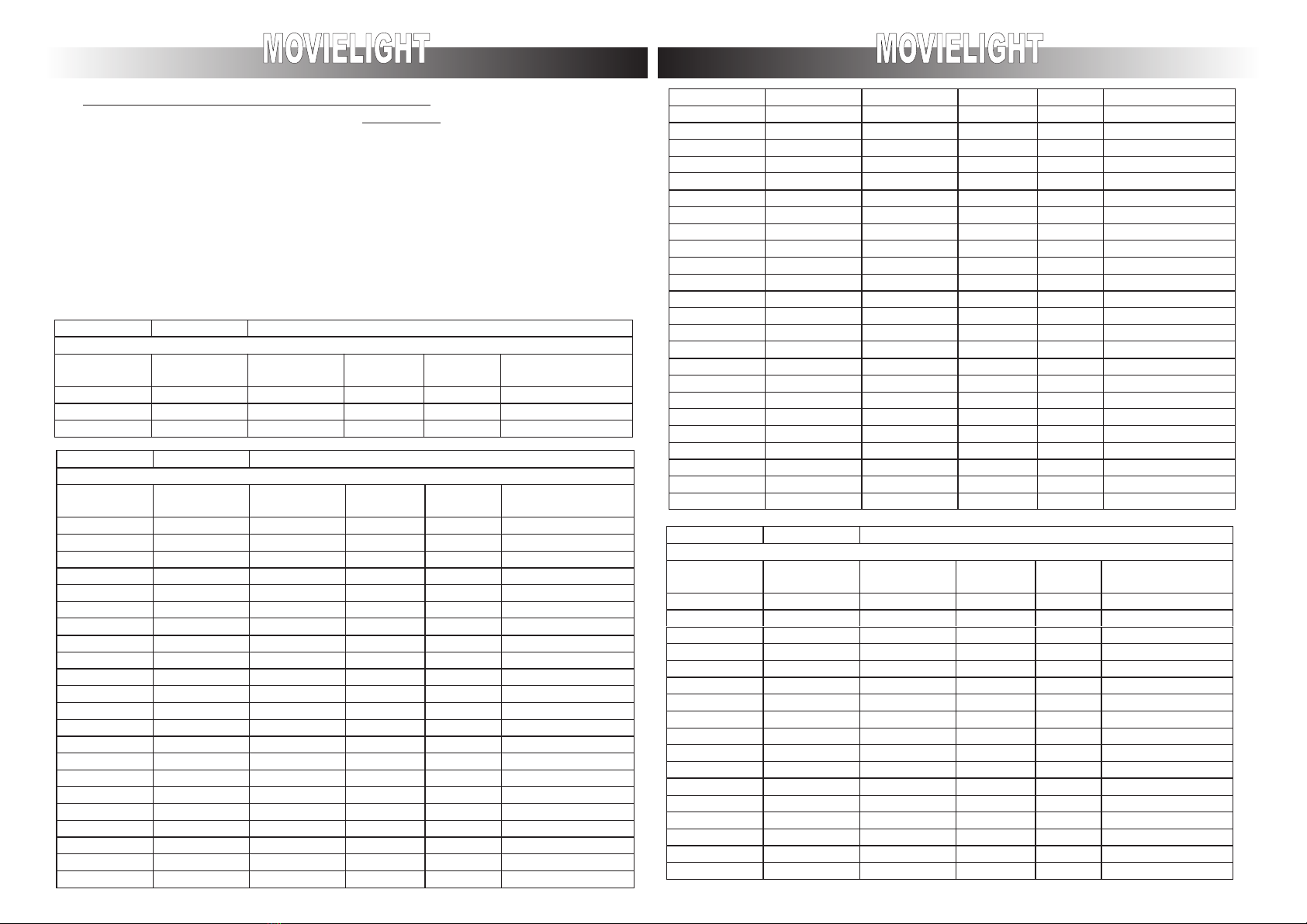
FUNCTIONAL ANOMALIES
Problems possible solutions
The device does not switch on control the fuse on the
backside of the device
The electronics does not work control the exact configuration
on the device
The devise on intermit turns on and of control the function of the fan
Projection of rays of light with halo control that the lamp has been
put in theRight position
Control the focus deriv
Luminosity reduction Exhausted lamp
Control that the lens are clean
For any other types of problems we strictly reccomend that a professional qualified
techniques is contacted
For the errors shown above and wrong definition of the DIP/SW., because of the only led
fixed for error indicating this one will be establish by the sign of the DMX to make the
device move. With an error of the photocell the device will keep on moving. Photocell
errors happen when during the reset of one of the two motors do not find its respective
photocell. In this case the device will respond to the DMX signal (if present), but that motor
will be probably not regulated
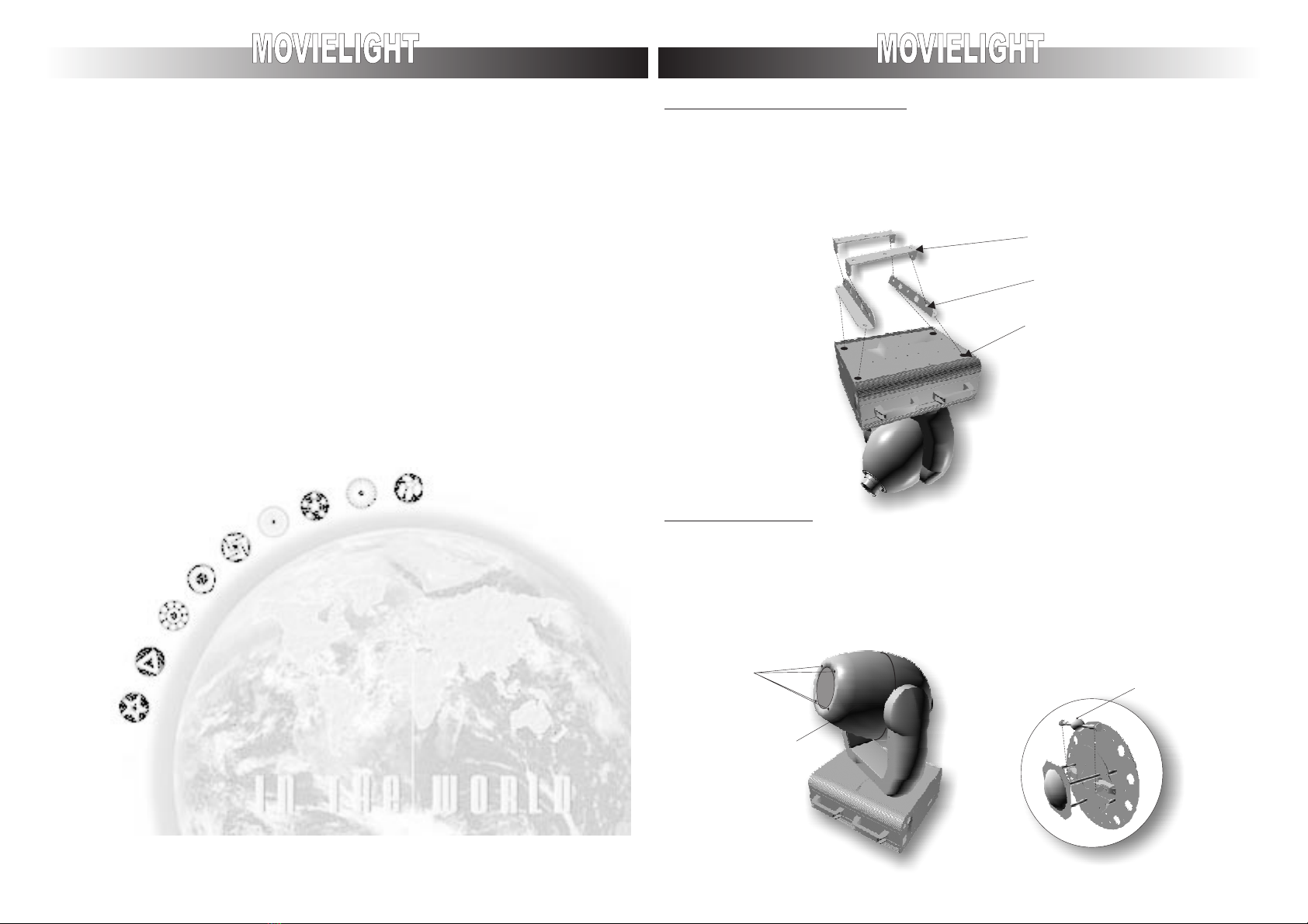
REPLACEMENT OT THE ROTATING GOBO
It is possible to change the gobos by removing from the device the 4 screws on the backside of it
and the tree screws in front of the movielight (fig1) remove the fixed spring from the gobo and
proceed with its replacement (fig1)
It is absolutely essential a regular cleaning of the removable gobos holder.
*DO NOT USEANY KIND OF SOLVENTTO CLEAN.
Fig.1
Gobo
OPEN
Gobo
FIXED GOBOS SPRING
ELECTIC NETWORK
ATTENTION
CONNECTION WITH THE SWITCHBOARD CONTROLLER
Switch on the device connecting the cable wire given with in the tension and frequency
indicated on the front side of the device. We advice you to put it in network with the proper
switch that way you can switch and turn them off separately
It is important to connect the device with earth connectio. Power absorption of the device is
of 800 VA
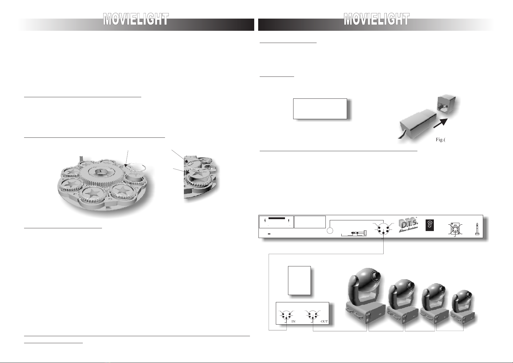
The Movielight works with digital dmx 512 (1990) signals. The connection between the device
and the switchboard or from device to device this has to be done with bipolar wire sheltered
with a screen section of at least 0.5 mm2, linked to the attached canon xrl-5 (current-tap and
plug given with the device) . It is important that the wires do not make contact between them and
also that they do not touch covering of the plug. The cover of the plug must not be connected to
anything.
Connect the command of the switchboard with the plug on the device that is shown with dmx in
on link with the another device putting its plug in dmx out concatenate all the other device
N=BLU
E=YELLOW/GREEN
L=BROWN
1
2
3
5
4
1
2
3
5
4
IN OUT
Fig.(1)
DMX 512
RISK OF ELECTRIC SHOCK
DO NOT OPEN
CAUTION
WARNING: SHOCK HAZARD-DO NOT OPEN
AVIS: RISQUE DE CHOC ELECTRIQUE-NE PAS OUVRIR
ACHTUNG: GEFAHRLICHE NETZSPANNUNG IM INNENTEIL-NICHT OFFNEN
ATTENTION:
1)OPERATE THIS UNITS ONLY WITH PROPER AC VOLTAGE
2)READ INSTRUCTION MANUAL CAREFULLY BEFORE OPERATION
3)TO AVOID THE RISK OF ELECTRIC SHOCK AND FIRE, DO NOT EXPOSE
THIS UNIT TO MOISTURE OR HIGH HUMIDITY
4)NO USER SERVICEABLE PARTS INSIDE
SERVICE PERSONNEL:
1)SEE SERVICE MANUAL BEFORE OPENING
2)DISCONNECT PLUG BEFORE OPENING
3)ALL PARTS MUST BE REPLACED BY ORIGINAL SPARE PARTS
C
C
DMX 512 OUTPUT
LINK
CONNECTION CABLES
5
3
42
13
2
1
1=GND
2=DATA-
3=DATA+
AC 9V
LINE IN
GROUND
SIGNAL
MIC-DO NOT COVER
MUSIC IN
1
2
3
5
4
DMX512
1 GND
2DATA-
3DATA+
4…
5…
ENGLISH