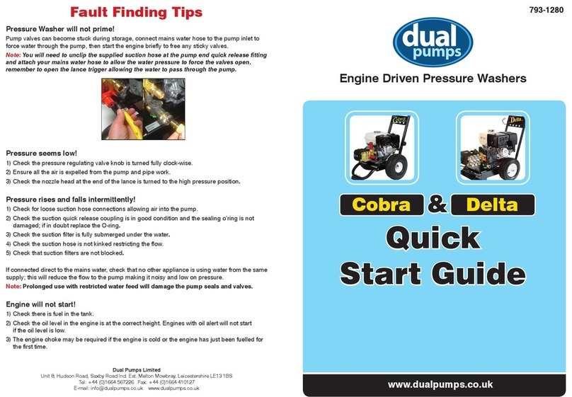
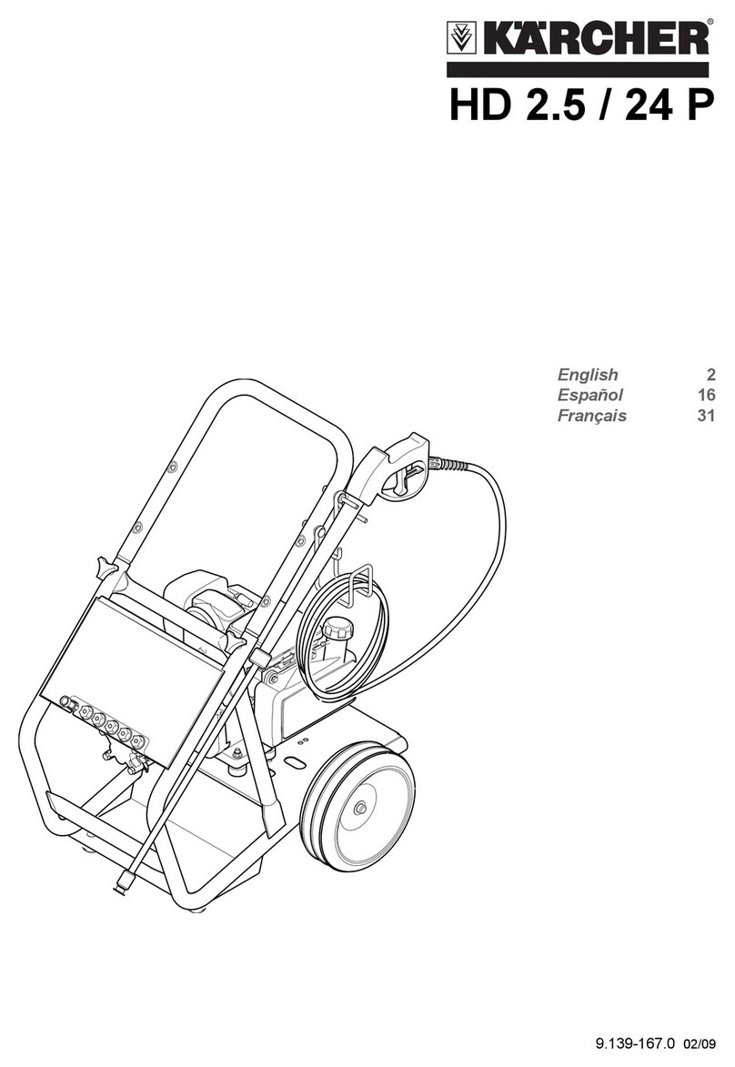
Dual Pumps Evolution E3T41200PLE User manual

Original Manufacturer
Instructions
793-1155
Evolution
v
pressure washers

Introduction
This manual and any other literature supplied must be read fully prior to the
initial operation of your machine and be stored for later use or for subsequent
owners. Pay particular attention to any instructions relating to operation and safety
and maintenance of the unit. Following these instructions will ensure optimum
performance, reliability and operator safety. The model and serial number on the cover
of this booklet must be quoted should you need to contact the dealer or manufacturer
regarding usage, maintenance and warranty queries.
Recommended Safety Standards & Directives
This manual highlights certain safety measures which must be taken in to
consideration when using this machine. However, each system designer, contractor
and operator must make their own risk assessments whilst considering their individual
application and environment and ensure the user is properly trained and wearing
protective clothing to the required regulatory standards. We recommend visiting the
Health and Safety Executive website at www.hse.gov.uk to be properly informed on
best practice in the UK.
Contents Page
1. Component Identification..........................................................................1-3
2. Technical Specification..............................................................................4-5
3. Intended and Proper Use - Commercial...................................................... 6
4. Safety Information .....................................................................................6-8
5. Safety Devices.............................................................................................. 8
6. Standard Accessories .................................................................................. 8
7. Pre-Operation Checks and Set Up .........................................................9-12
8. Start Up and Operation .........................................................................12-13
9. Stopping Procedure................................................................................... 13
10. Transporting ............................................................................................... 14
11. Decommissioning and Storage ................................................................. 14
12. Maintenance Information ........................................................................... 14
13. Loncin E3 Pressure Washer Maintenance Schedule ................................ 15
14. Troubleshooting ......................................................................................... 16
15. Disposal and Environmental Protection .................................................... 16
16. Warranty Information.................................................................................. 17
17. EC Declaration of Conformity .................................................................... 17

1
1. Component Identification
Item No. Main Machine Photos
1-1 Trolley Frame
1-2 Trolley Baseplate on Anti-Vibration
Rubbers
1-3 Engine
1-4 Gearbox
1-5 Gearbox Oil Sight Glass
1-6 High Presure Pump
1-7 Throttle Control Lever
1-8 Ignition Switch
1-9 Battery
1-10 Engine Oil Dipstick
1-11 Engine Oil Filler (also 2-6)
Item No. Main Machine Photos
2-1 Gearbox Oil Dipstick/Breather
2-2 Gearbox Oil Drain Plug
2-3 Pump Oil Dipstick/Breather
2-4 Pump Oil Sightglass
2-5 Pump Oil Drain Plug
2-6 Engine Oil Filler (also 1-11)
2-7 Fuel Tank
2-8 Fuel Filler Cap
1-1
1-2
1-3
1-5
1-4 1-9
1-8
1-7
1-6
1-10
2-2 2-5
2-6 2-7
2-8
2-4
2-1 2-3
1-11

2
E3T41200PLE, E3T30200PLE & E3T23250PLE
E3T25300PLE
E3T15500PLE, E3T18400PLE & E3T15400PLE
1. Component Identification continued
Item No. Pump Close ups
3-1 Unloader Valve
3-2 Safety Valve
3-3 Pulsation dampener (where fitted)
3-4 Suction Filter
3-5 Suction Filter Inlet
3-6 Bypass Outet
3-7 High Pressure Outlet
3-1
3-1
3-2
3-2
3-3
3-4
3-4
3-5
3-5
3-7
3-7
3-6
3-6
Awaiting Photo

3
1. Component Identification continued
ACCESSORIES
Item No. Accessories
4-1 Suction Hose Assembly and Filter*
4-2 Bypass Hose Assembly*
4-3 High Pressure Hose Assembly*
4-4 High Pressure Hose Inlet/Outlet Ports
4-5 High Pressure Lance Assembly*
4-6 Gun On/Off Trigger
4-7 Trigger Gun Safetly Latch
4-8 High Pressure Nozzle Outlet
4-9 Trigger Gun Inlet
4-2*4-1*
4-3*
4-4
4-4
4-5*
4-6
4-6
4-7
4-9
4-8
* The version you receive will vary depending
on the machine model specification.

4
2. Technical Specification
Notes
For the engine to reach it’s maximum power, and the unit to achieve full rated performance,
the machine must be run in for at least 10 hours. The engine’s performance diminishes as
altitude and ambient temperature increase. If the machine is to be used at altitude or with a high
ambient temperature please refer to the engine user manual for guidance and any necessary
precautions.
Model No. E3T41200PLE E3T30200PLE E3T23250PLE E3T25300PLE
Engine Information
Engine Loncin LC2V80FD5 V-Twin, 4-stroke, OHV, forced air cooling
Fuel Petrol
Net Power 18.0kW @ 3600 Rpm in accordance with SAE J1349
Nominal Rpm Engine 3600 - Pump 1450 via 2.2:1 gearbox
Starting Method Electric Start
Fuel Tank 14 Litres (approx)
Water
Connection
Max Feed Temperature 40°C
Minimum Feed Flow Rate 50 Lpm 36 Lpm 28 Lpm 30 Lpm
Maximum Feed Pressure 0.8 MPa - 8 Bar - 116 psi
Maximum Suction Depth 1 Metre (3.3 Feet) 0 Metre (0 Feet)
High Pressure
Performance
Flow Rate 41 Lpm†30 Lpm†23 Lpm†25 Lpm
Working Pressure 20 MPa
200 Bar
20 Mpa
200 Bar
25 Mpa
250 Bar
30 Mpa
300 Bar
Pressure Outlet Twin Outlet†Single Outlet
Nozzle Jet Size 15†10†07 065
Max. recoil force on
Spray Gun
127 N 115 N 115 N 115 N
Sound
Levels
Uncertainty K 3.9-0.24 m/s2
SPL LWA dB* 113
GSPL LWA dB** 116
Oils
Pump Oil Type SAE 15W/40
Pump Oil Capacity 1 L
Gearbox Oil Type SAE 80W/90 or ISO220
Gearbox Oil Capacity 0.28 L
Engine Oil Refer to engine user manual
Weights &
Dimensions
Dimensions 1100L x 620W x 800H (mm)
Weight 144.2 Kg 144.2 Kg 144.2 Kg 146.2 Kg
*SPL = Sound Power Level on equipment representative of this type
**GSPL = Guaranteed Sound Power Level for this equipment.
†if using machine with two operators the rated flow will be split between each outlet.
For example: If the machine has a rated flow of 30 Lpm each outlet will give 15 Lpm.

2. Technical Specification
Model No. E3T15400PLE E3T18400PLE E3T15500PLE
Engine Information
Engine Loncin LC2V80FD5 V-Twin, 4-stroke, OHV, forced air cooling
Fuel Petrol
Net Power 18.0kW @ 3600 Rpm in accordance with SAE J1349
Nominal Rpm Engine 3600 - Pump 1450 via 2.2:1 gearbox
Starting Method Electric Start
Fuel Tank 14 Litres (approx)
Water
Connection
Max Feed Temperature 40°C
Minimum Feed Flow Rate 18 Lpm 22 Lpm 18 Lpm
Maximum Feed Pressure 0.8 MPa - 8 Bar - 116 psi
Maximum Suction Depth 0 Metre (0 Feet)
High Pressure
Performance
Flow Rate 15 Lpm†18 Lpm†15 Lpm
Working Pressure 40 Mpa
400 Bar
40 Mpa
400 Bar
50 Mpa
500 Bar
Pressure Outlet Single Outlet
Nozzle Jet Size 035 035 030
Max. recoil force on
Spray Gun
78 N 83 N 78 N
Sound
Levels
Uncertainty K 3.9-0.24 m/s2
SPL LWA dB* 113
GSPL LWA dB** 116
Oils
Pump Oil Type SAE 15W/40
Pump Oil Capacity 1 L
Gearbox Oil Type SAE 80W/90 or ISO220
Gearbox Oil Capacity 0.28 L
Engine Oil Refer to engine user manual
Weights &
Dimensions
Dimensions 1100L x 620W x 800H (mm)
Weight 144.2 Kg 144.2 Kg 142.2 Kg
Notes
For the engine to reach it’s maximum power, and the unit to achieve full rated performance,
the machine must be run in for at least 10 hours. The engine’s performance diminishes as
altitude and ambient temperature increase. If the machine is to be used at altitude or with a high
ambient temperature please refer to the engine user manual for guidance and any necessary
precautions.
*SPL = Sound Power Level on equipment representative of this type
**GSPL = Guaranteed Sound Power Level for this equipment.
5

6
This machine is intended for Commercial use and is not suitable for normal
housekeeping purposes by private persons whereby there may be a source
of danger to the public. The machine must be used solely by professional
contractors who are properly trained and wearing protective clothing to the
required health & safety, and national legislation regulatory standards.
The intended use of this high pressure cleaner is exclusively for:
• Cleaning of machines, vehicles, buildings, and tools with clean, soft water
and, if necessary, with detergents approved by the manufacturer.
• Descaling and clearing of blocked pipes and hydro sandblasting by means
of special accessories recommended by the manufacturer.
• Use with accessories rated to the performance of the high pressure cleaner.
The high pressure cleaner MUST NOT be used:
• To wash people, animals, live electrical equipment, delicate objects or the
high pressure cleaner itself.
• In environments in which explosive or corrosive atmospheres are present.
• In poorly ventilated areas where exhaust gases from the engine could cause
harm to the user and public unless adequate ventilation is approved by
national labour authorities.
• By persons (including children) with reduced physical, sensory or mental
capabilities, or lack of experience or necessary knowledge.
Any other use must be considered improper and the manufacturer cannot
be considered responsible for possible damages caused by the improper or
incorrect use.
!
3. Intended and Proper Use - Commercial
4. Safety Information
!
!
!
WARNING - Not following the instructions given below may cause serious
injury to persons, harm to the environment and damage to equipment.
This machine must only be used in applications covered in section 3, Intended
and Proper Use.
Use the following personal protective equipment (PPE)
Wear protective clothes
Wear protective ear muffs
Wear protective gloves
Wear a face shield
Wear safety boots

7
!
!
!
!
!
!
!
!
!
!
This machine has been designed for use only with cleaning agents approved by
the manufacturer. The use of other cleaning agents or chemicals may adversely
affect the safety of the machine.
High pressure jets can be dangerous if subject to misuse. The jet must not be
directed at persons, animals, live electrical equipment or the machine itself.
Do not use the machine within range of persons unless they wear protective
clothing.
Do not direct the jet against yourself or others in order to clean clothes or foot-
wear.
Risk of explosion - Do not spray flammable liquids.
High pressure cleaners shall not be used by children or untrained personnel.
High pressure hoses, fittings and couplings are important for the safety of
the machine. Use only hoses, fittings and couplings recommended by the
manufacturer.
To ensure machine safety, use only original spare parts from the manufacturer
or approved by the manufacturer. USE OF NON APPROVED PARTS WILL VOID
WARRANTY.
Water that has flowed through backflow preventers is considered to be non-
potable
Do not use if machine, component part, or any accessory is damaged or worn.
Battery Warnings - Please observe the following warnings when handling
batteries.
Machine not suitable for connection to the potable water mains.
!
Observe the directions on the
battery and manufacturers
instructions
Wear an eye shield
Keep away children from acid
and batteries
Risk of explosion
Fire, sparks, open light and
smoking not allowed
Danger of causticization
First aid
Warning note
Disposal
Do not throw the battery in the
dustbin

8
Risk of explosion! Do not put tools or similar on the battery, i.e. on the terminal
poles and cell connectors.
Risk of injury! Ensure that wounds never come into contact with lead. Always
clean your hands after having worked with batteries.
!
!
Safety devices serve to protect the user and machine and must not be rendered
inoperative or their functions bypassed. Safety devices must not be tampered
with by the user as this could result in serious injury and/or damage to the
machine.
Unloader Valve or Bypass Valve - Pre-set by the manufacturer, for regulating
the working pressure and allowing the pumped fluid to return to the supply tank
(or to atmosphere) when the operator closes the trigger gun.
Safety Valve - Either set and sealed by the machine manufacturer or factory set
at source, for protecting the pump and machine should the main control valve
malfunction or the machines maximum pressure be exceeded.
Trigger Gun Safety Latch - Safety stop for locking the trigger gun lever in the
closed position so it cannot be opened accidentally.
!
5. Safety Devices
6. Standard Accessories
All Loncin powered Evoultion3 pressure washers are supplied with the following
accessories. Make sure all the items listed are included when unboxing for the first
time.
• High pressure lance assembly.
• 10m high pressure hose assembly.
• 3m bypass hose assembly with hose clamps.
• 3m suction hose assembly with suction filter and hose clamps.
In case of transport damage inform vendor immediately.
When unpacking the product, make sure that no accessories are missing and
that none of the package contents have been damaged.

9
7. Pre-Operation Checks and Set Up
CHECKS
DAMAGE - Before each period of use ensure the machine and all components and
accessories are complete and undamaged. Take care to ensure the suction hose and
bypass hoses are kink-free.
ENGINE OIL - Use the engine dipstick to check the engine oil level, refer to the
engine manufacturers handbook for levels and oil types.
TRAVEL PLUGS - On the pump and gearbox REMOVE THE RED TRAVEL PLUGS
and replace with the appropriate yellow-topped oil dipstick/breather
OIL LEVELS - Check oil levels on the sight glasses on both the gearbox and pump,
the oil should be half way up the sight glasses - ensure machine is on a level surface.
Travel PlugsTravel Plugs
Pump sight glassPump sight glass Gearbox sight glassGearbox sight glass
Breather/DipstickBreather/Dipstick

10
7. Pre-Operation Checks and Set Up continued
FILTERS - Ensure both the suction hose filter and pump inlet filter are clean.
TYRES - Ensure all four tyres are
inflated to 2 Bar (30 psi).
BATTERY - Connect the battery leads,
RED TO +VE, EARTH TO -VE.
FUEL - Fill the fuel tank with petrol fuel, refer the engine manufacturers handbook
for fuel types. DO NOT USE BIOFUEL
CHECKS

11
7. Pre-Operation Checks and Set Up continued
SET UP
Connect the suction filter and hose
assembly to the suction filter hose barb.
Ensure all connections are tight and
leak free. Air leaks on the suction side
will impair the machine performance
and damage components. Place suction
filter in water supply tank ensuring it
remains under the water level.
Connect the bypass hose to the unloader
valve bypass outlet. Place the other end
in the water supply tank taking care to
ensure it is a good distance from the
suction filter to minimise any turbulence
near the suction filter.
Connect one end of the high pressure
hose assembly to the high pressure
outlet of the unloader valve.
Connect the other end of the high
pressure hose assembly to the lance
assembly inlet. Ensure the trigger gun
safety latch is engaged to prevent
accidental operation.
Suction HoseSuction Hose
Bypass HoseBypass Hose
High Pressure HoseHigh Pressure Hose
Lance AssemblyLance Assembly
1
2
3
4
Safety Latch ON

12
!
8. Start Up and Operation
Before starting the machine the user must be familiar with the engine
starting and stopping procedure and any safety requirements stated in the
engine manufacturer’s handbook supplied with the unit.
For twin outlet only - If using machine
with two operators the rated flow will be
split between each outlet.
For example: If the machine has a
rated flow of 30 Lpm each outlet will
give 15 Lpm.
Twin OutletTwin Outlet
NOTE
!WARNING: Do not let the pump idle in By-Pass for lengthy periods, if you
intend to break from work for more than 3 minutes, switch the machine off.
Should the machine run for a longer period, the temperature of the re-
circulating water will increase rapidly and could risk damaging the pump
seals. Running pressure washers should never be left unattended.
7. Pre-Operation Checks and Set Up continued
Open the Fuel Tap.
The Fuel Tap is located on
the underside of the fuel tank,
there is a label positioned
on the back of the fuel tank
pointing out its location.
Fuel Tap is in ON position here

13
9. Stopping Procedure
• DRAIN PUMP - Remove the suction hose from the water supply tank and drain
the water from the pump by allowing the machine to run for a few seconds with the
trigger gun open until no water is coming from the high pressure jet.
• SHUTDOWN ENGINE - In keeping with the information from the engine
manufacturer’s manual, reduce the engine revs and switch the ignition switch to the
off position.
• RELEASE RESIDUAL HIGH PRESSURE WATER - Pull the trigger gun to release
any trapped pressure in the delivery line.
• TRIGGER GUN SAFETY LATCH - Ensure the trigger gun safety latch is engaged to
prevent accidental operation.
• COOL DOWN - Wait for the machine to cool down before transporting.
8. Start Up and Operation continued
Move the throttle lever to half revs.
Pull out the choke if starting from cold.
Turn the ignition switch clockwise.
When engine runs smoothly, increase the revs as required.
Push in the choke if used in step

12. Maintenance Information
Maintenance and servicing of the machine must only be undertaken by
suitably trained and qualified technicians.
Unloader Valves and Safety Valves must only be adjusted and serviced by
suitably trained and qualified technicians.
Ensure all steps from the Decommissioning & Storage section have been
carried out before starting any work on the machine.
• ENGINE - Refer to engine manufacturer’s handbook for specific engine
maintenance and service schedules.
!
!
!
14
10. Transporting
During transportation the machine must be secured using suitably rated straps
and fixings. Ensure the fuel is turned off at the fuel tap.
The machine must only be lifted and secured by attaching lifting/security
equipment to the main frame. No lifting/security straps should come in to contact
with the engine, gearbox, pump, valves or filter.
!
!
11. Decommisioning and Storage
• ENGINE - Follow the guidelines in the relevant section of engine manufacturer’s
handbook.
• HOSES AND ACCESSORIES - Disconnect hoses and lance assembly. Ensure all
water is expelled from hoses and lance, check for damage and store in a manner
that will not kink the hose assemblies.
• PRESSURE WASHER - Ensure all the water is expelled from the pump by turning
over the engine.
• BATTERY - Disconnect battery and ensure the battery pole terminals and pole
terminals are adequately protected with pole grease.
• STORAGE - Machine and accessories must be stored in dry and frost-free
environment.

13. Loncin powered Evolution3 Pressure Washer
Maintenance Schedule
Activity Each/
First Use
3 months or
first 50 Hours
12 months or
250 hours
Inspect / top up oil levels
Engine *
Gearbox *
Pump *
Change Oil
Gearbox (SAE90 Gear Oil) * *
Pump (SAE20/30 Pump Oil) * *
Change Engine Oil Refer to Engine Manufacturer's handbook
Water Suction Filter
Clean water inlet filter on suction hose
Clean secondary water filter
*
*
Check Air Filter Refer to Engine Manufacturer's handbook
Inspect high-pressure hose and its connection
for tightness and damage *
Inspect suction hose and its connections for
tightness and damage *
High Pressure Jet
Inspect *
Change *
Pneumatic tyres
Check/Inflate tyre pressures (2.0bar, 30psi)
*
*
Check & Change Fuel Filter Refer to Engine Manufacturer's handbook
Battery Charging Information
Risk of injury! Comply with safety regulations on the handling of batteries.
Observe the directions provided by the manufacturer of the charger.
• Disconnect battery.
• Connect positive terminal cable from the charger to the positive pole
connection on the battery.
• Connect negative terminal cable from the charger to the negative pole
connection on the battery.
• Plug in mains connector and switch on charger.
• Charge battery using lowest possible level of charging current.
!
15

Do not release oils and fuel into the environment. Dispose of all oils and fuels through
suitably certified outlets according to local regulations.
15. Disposal and Environmental Protection
Old appliances contain valuable materials that can
be recycled; these should be sent for recycling.
Batteries, oil, and similar substances must not enter the
environment. Please dispose of your old appliances
using appropriate collection systems.
Please do not release engine oil, fuel oil, diesel and
petrol into the environment. Protect the ground and
dispose of used oil in an environmentally-clean manner.
The packaging material
can be recycled. Please do
not throw the packaging
material into household
waste; please send it for
recycling.
16
14. Troubleshooting
Symptom Possible Cause Remedy
Pump running normally
but pressure low.
Pressure Regulator valve
Pump sucking air.
Check and adjust
Check water supply and
possible air ingress.
Nozzle badly worn Check and/or replace
Worn piston packing Seek professional advice
Fluctuating pressure Blocked water filter Check filter, clean or
replace if necessary.
Pump sucking air Check integrity of suction
hose and connections.
Pressure low after a long
period of normal use. Nozzle badly worn Check and/or replace
Pump noisy. Pump sucking air Check integrity of suction
hose and connections.
Excessive temperature of Reduce temperature to
liquid in pump below 60ºC, do not allow
pump to idle for long periods.
Blocked water filter Check filter, clean or
replace if necessary.
Worn bearing or valves Seek professional advice
Presence of water in oil. Ingress through breathers Replace oil, do not wash
engine or pump
Worn oil seals Seek professional advice
Water dripping from under pump. Worn piston packing Seek professional advice
Oil dripping from
pump/gearbox/engine. Worn oil seal Seek professional advice
Excessive vibration in Water supply low Check adequacy of water
lance/delivery line. supply. Ensure suction
filter is below water level.
Ingress of air into suction Check integrity of suction
line hose and connections.
Irregular functioning of Seek professional advice
valves Check filter, clean or
replace if necessary.
Blocked water filter

17. UKCA & EC Declaration of Conformity
We hereby declare that the machinery described above complies with the relevant
basic health and safety requirements of the UKCA & EU Directives, both in its’ basic
design and construction. This declaration shall cease to be valid if the machine is
modified without our prior approval.
Declaration of Conformity
Equipment Type
High pressure cleaner - Engine Driven
Relevant UKCA Directives
Supply of Machinery (Safety) Regulations 2008
Electrical Equipment (Safety) Regulations 2016
Noise Emission in the Environment by Equipment for use Outdoors Regulations 2001
The Restriction of the Use of Certain Hazardous Substances in Electrical and Electronic Equip-
ment Regulations 2012
Relevant EU Directives
2006/42/EC - Machinery Directive
2014/30/EU - Electromagnetic Compatibility (EMC) Directive
2000/14/EU – Noise Emissions Directive
2011/65/EU - RoHS Directive
Applied Harmonised Standards
EN60335-1-2012-A13-2017
EN60335-2-79-2012
EN1829-1-2010
EN1829-2-2008
EN4871-2009
Manufacturer
Dual Pumps Ltd, Saxby Road Industrial Estate, Melton Mowbray, LE13 1BS. United Kingdom
Person authorised to compile the technical file & declaration
Tom Herridge, Director
Signed –
Date – 13/10/2020
17
16. Warranty Information
For warranty terms refer to Section 7
of our Terms and Conditions at
www.dualpumps.co.uk/company/legal
or scan the QR code

Unit 8, Hudson Road
Saxby Road Ind. Est.
Melton Mowbray
Leicestershire LE13 1BS
Telephone: +44 (0)1664 567226 Fax: +44 (0)1664 410127
DP-E3LM-V1.0-08/22
This manual suits for next models
6
Table of contents
Other Dual Pumps Pressure Washer manuals

Dual Pumps
Dual Pumps CF10135PHR User manual

Dual Pumps
Dual Pumps CF10135PHR User manual

Dual Pumps
Dual Pumps THOR BLACK EDITION User manual

Dual Pumps
Dual Pumps THOR DIESEL User guide

Dual Pumps
Dual Pumps Evolution GF10150PHR User manual

Dual Pumps
Dual Pumps LCT12150PLR User manual

Dual Pumps
Dual Pumps LC Series User manual

Dual Pumps
Dual Pumps Cobra User manual