Ducoterra SolaRay User manual

1645 JILL’S COURT, SUITE 108, BELLINGHAM, WA 98226 | www.ducoterra.com | in[email protected] | 360.788.4200
DUCOTERRA® SolaRay Electric Infrared Heating Ceiling Panels
•Attractive low-profile appearance
•High performance materials
•Multiple Sizes and Mounting Options
•Qualifies for LEED Certification
Ducoterra’s SolaRay ETL-Listed radiant ceiling panels are cost-effective, efficient heating solutions for both residential and
commercial environments and are easily installed in either new or existing construction. SolaRay panels are ideal for
augmenting heating in conjunction with ductless heat pumps or forced air systems, or for heating entire homes.
SolaRay panels are ideal alternatives for:
▪Baseboard and wall heater alternative or replacement
▪Remodel projects without existing ductwork (garages, guest houses, add-on rooms)
▪Areas with drafts, many windows, or with “cold spots”
▪Washrooms, shower rooms and other spaces with high ventilation rates
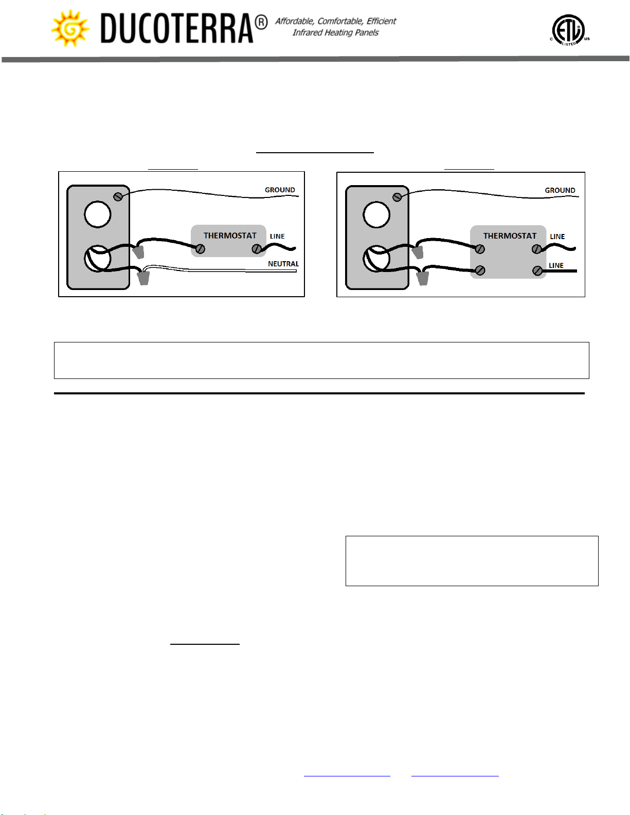
IMPORTANT INSTRUCTIONS
When using electrical appliances, basic precautions should always be followed to reduce the risk of fire, electric shock, and
injury to persons, including the following:
1) Read all instructions before installing and using this heater.
2) To prevent possible electrical shock, disconnect ALL power coming to the heater at main service panel before wiring or
servicing
3) Extreme caution is necessary when any heater is used by or near children or invalids and whenever the heater is left
operating and unattended.
4) Do not operate any heater after it malfunctions. Disconnect power at service panel and have heater inspected by a
reputable electrician before reusing.
5) Panels are intended for ceiling installation only. Do not install on walls, floor, etc. Do not use outdoors.
6) To disconnect heater, turn controls to off, and turn off power to heater circuit at main disconnect panel.
7) A heater has hot and arcing or sparking parts inside. Do not use it in areas where gasoline, paint, or flammable vapors or
liquids are used or stored.
8) Use this heater only as described in this manual. Any other use not recommended by the manufacturer may cause fire,
electric shock, or injury to persons.
1. Introduction
Ducoterra’s SolaRay panels are designed to heat living
and working spaces rapidly and efficiently by radiant
heating. Like the sun, these panels will create a warm
environment for all people and objects within line of
sight of the panel surface. They are designed to be
surface mounted on ceilings or for installation in a T-bar
grid.
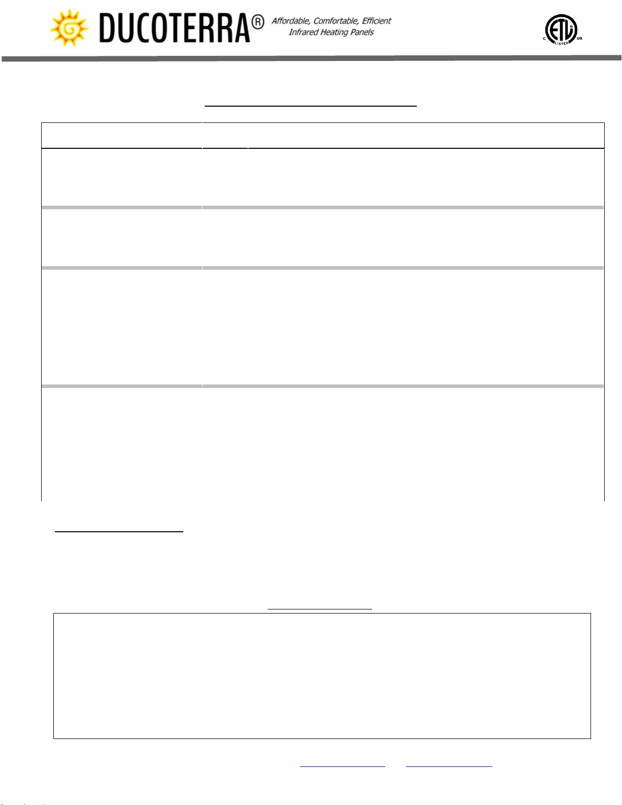
2. Installation Layout Guidelines
In a standard 8’ ceiling room, these heating panels will
cover approximately 10 times the floor square footage as
panel size (e.g. a 2x4 panel will cover approximately 48
to 80 square feet of floor space). They may be installed
at zero clearance to adjoining walls and adjacent panels,
but optimal coverage is obtained by spacing the panels
to cover the floor space efficiently.
As maximum panel efficiency is obtained within a 45
degree angle of the panels, spacing panels 2’ off walls
and approximately 4’ from other panels will generally
cover a room sufficiently. Panels may need to be
positioned differently or installed at higher/lower
wattage densities depending on specific room
configurations, insulation, heating requirements, and
other factors.
3. Environment Insulation Requirements
For proper functionality, the heated space should be
insulated appropriately. Optimal panel operation is
achieved if walls and ceilings are insulated according to
ASHRAE 189 standards in accordance with your local

1645 JILL’S COURT, SUITE 108, BELLINGHAM, WA 98226 | www.ducoterra.com | in[email protected] | 360.788.4200
climate zone. Heating panel connection box must not be
covered with insulation material after installation.
Insulation in panel has an R value of 10.
4. Wiring Requirements and Guidelines
Heating panel has two 10” 12 AWG leads for connecting
to standard #12 power supply with wire-nut inside
attached connection box. See appropriate wiring
diagrams for details (Figure 3 below).
!WARNING: To avoid the risk of electrical shock,
personal injury or death, disconnect all electrical
power before installing or performing maintenance
on this panel.
The wiring, installation, and electrical hookup of this panel
must conform to local and national codes. The use of GFCI
circuits in high moisture areas is recommended. Total
wattage of heating panels per circuit must not exceed 80% of
circuit capacity.
5. Thermostats
Panels should be installed in conjunction with a line
voltage or 24V thermostat. Measure voltage and branch
circuit amperage to determine wattage and panel circuit
load. The thermostat should be located in the same
room on a side wall and not directly under the ceiling
panel.
6. Surface Mounting Guidelines
Panels may be mounted to joists, wood, or other
penetrable surfaces using appropriate hardware.
Included in our installation kit are toggle bolts to attach
the panels to standard drywall ceilings. Alternatively, the
mounting holes are designed to accommodate #8 –2”
pan head screws. Joint between panel and mounting
surface should be sealed with heat resistant (rated to a
minimum of 100C) caulking for maximum performance.
Surface of panel may be painted with a quality water
based flat paint to customize appearances. (See Figure 1
below)
! WARNING: DO NOT puncture panel with screws,
nails, or any other device. Panel must be mounted
only through the provided mounting holes.
SURFACE MOUNTING INSTALLATION
1. Cut appropriately sized hole for panel connection box and insure clearance from insulating material.
2. Attach connection box to back of panel using provided hardware.
3. Attach power supply leads to the panel leads in connection box.
4. Position on ceiling in desired mounting location.
5. Attach panel to ceiling using provided mounting toggle bolts and washers or alternatively screws for wood ceilings
6. Insert plastic caps to close mounting holes after allowing time to adjust installation if necessary. Caps are non-removable.
Figure 1 –Surface Mounting
SEE SCHEMATIC ON LAST PAGE FOR ADDITIONAL DETAILS ON SURFACE MOUNTING
! Be sure electricity is turned off at main switch before wiring to prevent possible injury from electric shock.

1645 JILL’S COURT, SUITE 108, BELLINGHAM, WA 98226 | www.ducoterra.com | in[email protected] | 360.788.4200
WIRING DIAGRAMS
120 VOLTS 240 VOLTS
Figure 3 –Thermostat wiring connections for panels
! WARNING: Panel must NOT be wired to higher voltage than label voltage. Verify that the power supply
voltage coming to the heater matches the voltage printed on the heater label.
TESTING INSTALLATION
After installation, the heating circuit should be checked
to ensure all panels have been installed properly and are
functioning normally. With power available, measure the
branch load with an amp meter. The amp meter value
should agree with calculated load –if not, recheck the
installation. A physical check of operation can also be
made –with power to the panels, they should be warm
to the touch and prolonged contact should be
uncomfortable.
If no power is available to test the circuit, the use of an
ohmmeter is required. Measure the resistance of the
load circuit, isolated from other circuits. The measured
resistance of the heating circuit should match the
calculated resistance. The resistance can be calculated
with the following formula:
𝑅𝑒𝑠𝑖𝑠𝑡𝑎𝑛𝑐𝑒 = 𝑉𝑜𝑙𝑡𝑠 ∗ 𝑉𝑜𝑙𝑡𝑠
𝑊𝑎𝑡𝑡𝑠
HEATING PANEL OPERATION
Ensure panels have been properly installed prior to
operation. Radiant heat ceiling panels function best in a
zone heating configuration. Use a programmable
thermostat to apply appropriate setbacks to spaces that
are unoccupied. Optimal comfort with a radiant system
is typically obtained at air temperatures of around 60-
62F.
It is recommended that the panels are dusted and
cleaned with a damp cloth every 6 months. Do not use
harsh cleaners or abrasives or damage to panel surface
may result. Do not lubricate. Make sure to disconnect
power to panels at breaker box before cleaning, and
allow panel to reach room temperature.
! WARNING: Panel contains no user serviceable
parts and opening the heating unit will void the
warranty.
HEATING PANEL MAINTENANCE
Ducoterra heating panels require no maintenance and
carry a Lifetime warranty. An occasional dusting & wipe
down with a damp cloth every 6 months to maintain
appearances is all that is necessary. Do not use harsh
cleaners or abrasives or damage to panel surface may
result. Make sure to disconnect power to panels at
breaker box before cleaning and allow panel to reach
room temperature. If your panel ceases to operate at any
time during the warranty period, contact Ducoterra to
obtain a replacement panel at no charge (installation and
shipping costs not covered).

1645 JILL’S COURT, SUITE 108, BELLINGHAM, WA 98226 | www.ducoterra.com | in[email protected] | 360.788.4200
STANDARD MODEL SPECIFICATIONS
Model #
Volts
Watts
Amps
BTUs
Dimensions
Mounting Holes
Weight
(lbs.)
120AIP2-200
120
200
1.6
682
22.50” x 23.75” x 1/2"
4 holes - 21.00”W 22.25"L
8.5
240AIP2-200
240
200
0.8
682
22.50” x 23.75” x 1/2"
4 holes - 21.00”W 22.25"L
8.5
120AIP2-250
120
250
2.0
853
22.50” x 23.75” x 1/2"
4 holes - 21.00”W 22.25"L
8.5
240AIP2-250
240
250
1.0
853
22.50” x 23.75” x 1/2"
4 holes - 21.00”W 22.25"L
8.5
120AIP3-300
120
300
2.5
1,023
22.50” x 35.75” x 1/2"
6 holes - 21.00”W 17.125"L
12.5
240AIP3-300
240
300
1.2
1,023
22.50”x 35.75” x 1/2"
6 holes - 21.00”W 17.125"L
12.5
120AIP3-375
120
375
3.1
1,279
22.50”x 35.75” x 1/2"
6 holes - 21.00”W 17.125"L
12.5
240AIP3-375
240
375
1.5
1,279
22.50”x 35.75” x 1/2"
6 holes - 21.00”W 17.125”L
12.5
120AIP4-400
120
400
3.3
1,365
22.50”x 47.75” x 1/2"
6 holes - 21.00”W 23.125"L
16.0
240AIP4-400
240
400
1.6
1,365
22.50”x 47.75” x 1/2"
6 holes - 21.00”W 23.125"L
16.0
120AIP4-500
120
500
4.1
1,706
22.50”x 47.75” x 1/2"
6 holes - 21.00”W 23.125"L
16.0
208AIP4-500
208
500
2.4
1,706
22.50” x 47.75” x 1/2"
6 holes - 21.00”W 23.125"L
16.0
240AIP4-500
240
500
2.0
1,706
22.50” x 47.75” x 1/2"
6 holes - 21.00”W 23.125"L
16.0
120AIP4-750
120
750
6.2
2,559
22.50” X 47.75” X 1/2”
6 holes –21.00”W 23.125”L
16.0
208AIP4-750
208
750
3.6
2,559
22.50” X 47.75” x 1/2”
6 holes –21.00”W 23.125”L
16.0
240AIP4-750
240
750
3.1
2,559
22.50” X 47.75” x 1/2”
6 holes –21.00”W 23.125”L
16.0
120AIP6-600
120
600
5.0
2,047
22.50” x 71.75” x 1/2"
8 holes - 21.00”W 23.417"L
24.0
240AIP6-600
240
600
2.5
2,047
22.50” x 71.75” x 1/2"
8 holes - 21.00”W 23.417"L
24.0
120AIP6-750
120
750
6.2
2,559
22.50” x 71.75” x 1/2"
8 holes - 21.00”W 23.417”L
24.0
208AIP6-750
208
750
3.6
2,559
22.50” x 71.75” x 1/2"
8 holes - 21.00”W 23.417"L
24.0
240AIP6-750
240
750
3.1
2,559
22.50” x 71.75” x 1/2"
8 holes - 21.00”W 23.417"L
24.0
120AIP6-1000
120
1000
8.3
3,413
22.50” x 71.75” x 1/2”
8 holes –21.00”W 23.417”L
24.0
208AIP6-1000
208
1000
4.8
3,413
22.50” x 71.75” x 1/2”
8 holes –21.00”W 23.417”L
24.0
240AIP6-1000
240
1000
4.2
3,413
22.50” x 71.75” x 1/2”
8 holes –21.00”W 23.417”L
24.0
INCLUDED COMPONENTS
•Radiant heating panel
•Heavy duty toggle bolts
•Covers for mounting holes
•User documentation
LIMITED WARRANTY
Ducoterra’s SolaRay radiant ceiling panels are warranted to the original owner against all defects in workmanship and materials for the lifetime
of the product. This warranty applies only for normal use of the product, and shall not be effective for products or parts which do not function
properly due to misuse, alteration, installation, accident, negligence, misapplication, modification, improper installation (including improper
operating voltage) or maintenance, or if any product or part has been serviced or repaired by other than DUCOTERRA.
THE ABOVE WARRANTY IS IN LIEU OF ALL OTHER WARRANTIES EXPRESSED OR IMPLIED AND ALL IMPLIED WARRANTIES OF MERCANTABILITY
AND FITNESS FOR A PARTICULAR PURPOSE. DUCOTERRA LLC WILL NOT BE LIABLE FOR CONSEQUENTIAL DAMAGES ARISING WITH RESPECT TO
THE PRODUCT, WHETHER BASED UPON NEGLIGENCE, TORT, STRICT LIABILITY, OR CONTRACT. IN NO EVENT SHALL THIS WARRANTY REQUIRE
MORE THAN THE REPAIR OR REPLACEMENT OF ANY PART OR PARTS WHICH ARE FOUND TO BE DEFECTIVE WITHIN THE EFFECTIVE PERIOD OF
THE WARRANTY. NO REFUNDS WILL BE GIVEN. IF REPLACEMENT PARTS FOR DEFECTIVE MATERIALS ARE NOT AVAILABLE, DUCOTERRA
RESERVES THE RIGHT TO MAKE PRODUCT SUBSTITUTIONS IN LIEU OF REPAIR OR REPLACEMENT.

1645 JILL’S COURT, SUITE 108, BELLINGHAM, WA 98226 | www.ducoterra.com | info@ducoterra.com | 360.788.4200
SolaRay Infrared Radiant Ceiling Panel Schematic and Assembly Details
Shown below is a SolaRay 2’ X 4’ panel schematic. The location of the Handybox is the same for all panels.
Spacing between holes is as shown in the Standard Model Specifications table.
This manual suits for next models
24
Table of contents
Other Ducoterra Heater manuals
Popular Heater manuals by other brands

Pinnacle Climate Technologies
Pinnacle Climate Technologies REMINGTON REM-60V-GFA-O User's manual & operating instructions

Plein Air
Plein Air ALM1200 instruction manual

BRAVILOR BONAMAT
BRAVILOR BONAMAT WHK-001 operating instructions

IVT
IVT GFH-10ATD instruction manual

Aerotech
Aerotech BT 400-46 Installation and operation maintenance

Sharper Image
Sharper Image EV-HT20 instruction manual