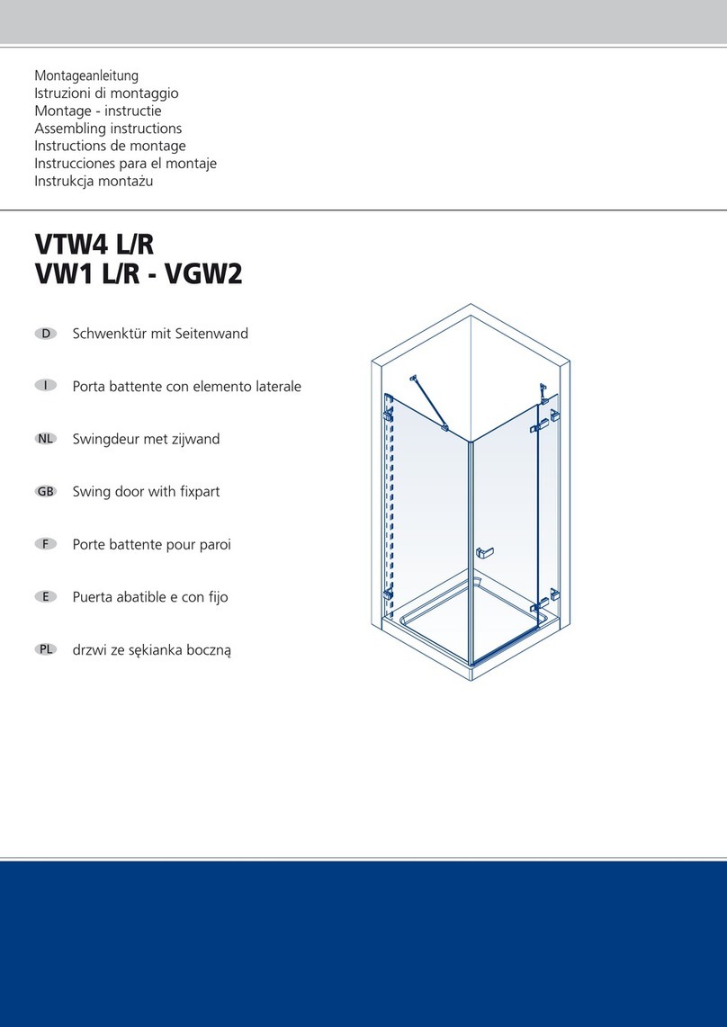
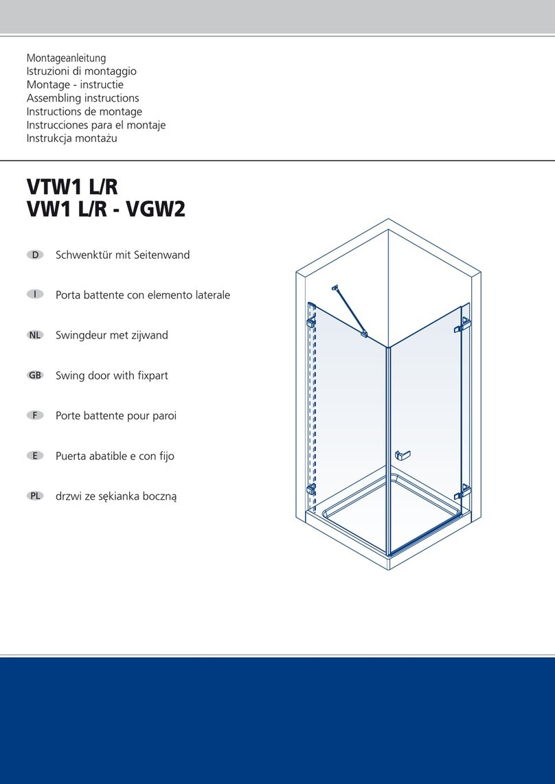
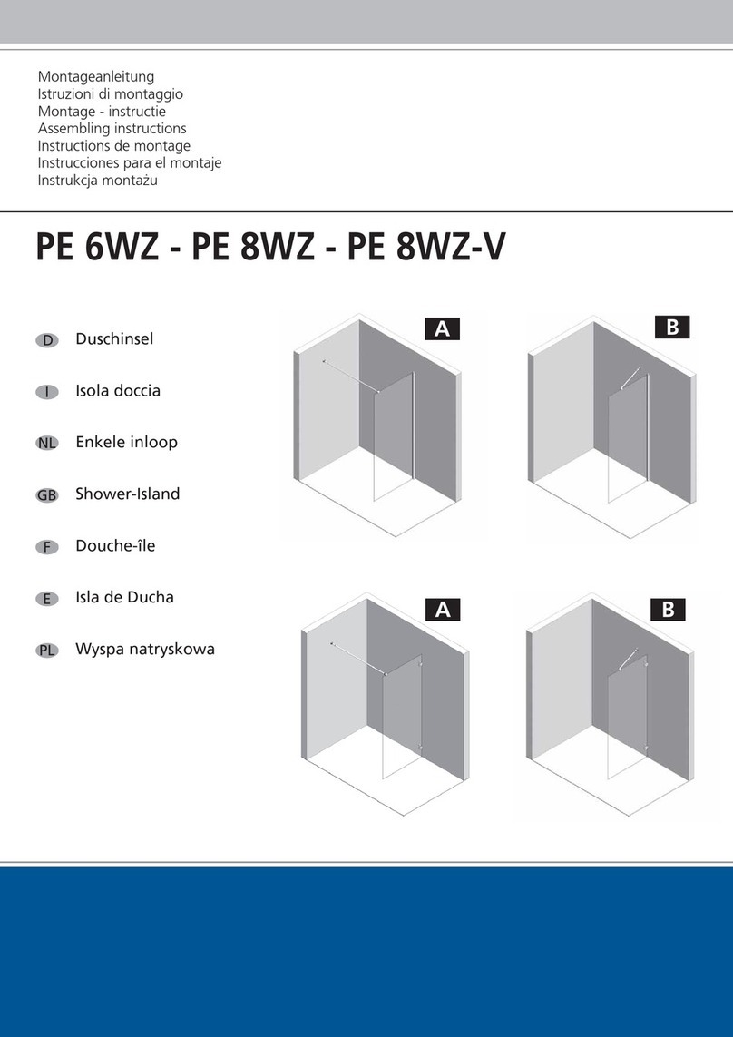
Duka TN2 L WV2 Installation guide

Montageanleitung
Istruzioni di montaggio
Montage - instructie
Assembling instructions
Instructions de montage
Instrucciones para el montaje
Instrukcja monta˝u
TN2 L/R - WV2
Schwenktür für Nische oder
mit verkürzter Seitenwand
Porta battente in nicchia o
con elemento laterale accorciato
Swingdeur voor nis of met
ingekorte zijwand
Swing door for niche or
with short fixpart
Porte battente pour niche ou
avec paroi latéral raccourie
Puerta abat. entre 2 paredes o
con fijo acortado
drzwi wahad∏owe do niszy lub
kompletacji ze s´kianka bocznà
F
GB
NL
I
D
E
PL

(ideal 10 mm)
1
(ideal 31 mm)

32
54
6 mm
2
IDEAL
31 mm
6 mm
1
2
1
3
IDEAL
10 mm
3
3,9 x 38

98
76
1
2
M 4 x 8
2
1
M 4 x 8

12
1110
3,5 x 9,5
2
1
15 mm
3 mm
_
+
1

13
14
1
4
5
2
22 mm
3
2
1
2

15
6 mm
23
4
3,9 x 38
16
1
5
1
2
+
_+
_
4
5
6
3
max 2 mm
7

17
18
1
3
4
5
2
5 mm

5
12
4
3
19 20
21
2
22
1

23
3
3
1
2
1
24
4
4
4

26
ca. 2 mm
1
2
ca. 20 mm
3
4
M 4 x 8
4
3
M 4 x 8
25
M 3,5 x 9,5

Schwenktür für Nische • Porta battente in nicchia • Swingdeur voor nis • Swing door for niche
Porte battente pour niche • Puerta abatible entre 2 paredes • drzwi wahad∏owe do niszy
1
2
3
4
5
6
7
8
9
10
11
12
13
14
15
16
17
18
19
20
21
21.5
21.9
21.10
22
22.1
22.2
22.3
22.4
22.5
22.6
23
23.1
23.2
23.3
23.4
23.5
23.13
23.14
23.16
23.19
23.20
24
25
26
27
28
29
Pos. Art.
PRHL105
PRHL106
PRHL107
PRHK068
PRHK069
PRHL017
PRB36912
PLL066
PLL116
PLL043
PLL044
PLK072
PLL115
PLMD39
PLJ547-PLJ548
GUMC192
GUML016
GUMN084
KLEL108
KLEL109
BGRL141
KLEL015
BGRL099
KLEL019
BGRL081
KLEL029
KLEL030
KLEL032
PLL031
PLL033
SRAM5x50
BGRL080
PRB33258
KLEL038
KLEL039
KLEL041
KLEL040
PLF197
PLF086
SRAM4x20 KF
SRAKF3938
KLE001
A10-ST10
A10-ST10
SRAM48KF
SRAKFS3595
SRAKFB3938
KLE001
77
Montageset
78
Mo
n
ta
g
e
a
n
l
e
i
84
VERMONTN2R/L-WV2 11.04.2006
79
31.1
30
32
31
30
31
31.1
32
77
78
79
84
Pos. Art.
KLEL 140
PLF 121 hard
PLF 121 soft
PLF 159
KLE 007
KLE 016
KLE L036
VERMONTN2R/L-WV2
9
23.20
23.16
23.14
23.4
23.2
23.13
23.1
23.16
23.14
18
3
21 21.9
21.5
21.10
21
20
19
28
29
12
29
28
28
19
29
20
3
21.9
21
21.10
21.5
21
15 13
7
16
15.1
8
11
14
27
28
29
28
29
28
29
4
5
14
27
14 27
12 10
17
17
6
22.1
25
24
26
26
22.3
22.2
22.6
22.5
23.3
23.5
23.19
22.4
23
22
TN2 R
Bei Ersatzteillieferungen sind folgende Angaben erforderlich: • Per ordini di pezzi di ricambio sono necessari i seguenti dati: • Bij onderdeelbestellingen zijn de volgende gegevens gewenst:
Spare parts need the following specification: • Pour toute commande de pièces détachées,il est nècessaire de fournir • Para pedir los repuestos, necesitamos de los siguientes datos:
W przypadku dostaw cz´Êci zamiennych wymagane sà nast´pujàce dane:
Breite / larghezza / breedte / width / largeur / anchura / szerokoÊç:
Höhe / altezza / hoogte / hight / hauteur / altura / wysokoÊç:
Farbe / colore / kleur / colour / couleur / color / kolor:
Glas / vetro / glaspaneel / Glas-type / verre / vidrio / element szklany:
15.1 BGRT072-BGRT073

1
2
3
4
5
6
7
8
9
10
11
12
13
14
15
16
17
18
19
20
21
21.5
21.9
21.10
22
22.1
22.2
22.3
22.4
22.5
22.6
23
23.1
23.2
23.3
23.4
23.5
23.13
23.14
23.16
23.19
23.20
24
25
26
27
28
29
Pos. Art.
PRHL105
PRHL106
PRHL107
PRHK068
PRHK069
PRHL017
PRB36912
PLL066
PLL116
PLL043
PLL044
PLK072
PLL115
PLMD39
PLJ547-PLJ548
GUMC192
GUML016
GUMN084
KLEL108
KLEL109
BGRL142
KLEL015
BGRL099
KLEL019
BGRL081
KLEL029
KLEL030
KLEL032
PLL031
PLL033
SRAM5x50
BGRL080
PRB33258
KLEL038
KLEL039
KLEL041
KLEL040
PLF197
PLF086
SRAM4x20 KF
SRAKF3938
KLE001
A10-ST10
A10-ST10
SRAM48KF
SRAKFS3595
SRAKFB3938
KLE001
77
Montageset
78
Mo
n
ta
g
e
a
n
l
e
i
84
VERMONTN2R/L-WV2 11.04.2006
79
31.1
30
32
31
30
31
31.1
32
77
78
79
84
Pos. Art.
KLEL 140
PLF 121 hard
PLF 121 soft
PLF 159
KLE 007
KLE 016
KLE L036
VERMONTN2R/L-WV2
9
23.20
23.16
23.14
23.4
23.2
23.13 23.1
23.16
23.14 18
3
21
21.9
21.5
21.10
21
20
19
28
29
1
2
29
28
28
19
29
20
3
21.9 21
21.10
21.5 21
15
13
7
16
15.1
810
14
27
28 29
28 29
28 29
4
5
14
27
14
27
12
11
17 17
6
22.1
25
24
26
26
22.3
22.2
22.6
22.5
23.3
23.5
23.19
22.4
23
22
TN2 L
Bei Ersatzteillieferungen sind folgende Angaben erforderlich: • Per ordini di pezzi di ricambio sono necessari i seguenti dati: • Bij onderdeelbestellingen zijn de volgende gegevens gewenst:
Spare parts need the following specification: • Pour toute commande de pièces détachées,il est nècessaire de fournir • Para pedir los repuestos, necesitamos de los siguientes datos:
W przypadku dostaw cz´Êci zamiennych wymagane sà nast´pujàce dane:
Breite / larghezza / breedte / width / largeur / anchura / szerokoÊç:
Höhe / altezza / hoogte / hight / hauteur / altura / wysokoÊç:
Farbe / colore / kleur / colour / couleur / color / kolor:
Glas / vetro / glaspaneel / Glas-type / verre / vidrio / element szklany:
15.1 BGRT072-BGRT073

Verkürzte Seitenwand • Elemento laterale accorciato • Ingekorte zijwand • Short fixpart
Avec paroi latérale raccourcie • Fijo acortado • skróconà Êciankà bocznà
1
2
3
4
5
6
7
8
9
9.1
9.2
9.3
9.4
9.5
9.13
9.14
9.16
9.19
9.20
10
11
12
13
14
15
16
78
Pos. Art.
PRHL105
PRHL106
PRHL107
PRHK070
PLL116
PLK071
KLEL108
KLEL109
BGRL080
PRB33258
KLEL038
KLEL039
KLEL041
KLEL040
PLF197
PLF086
SRAM4x20KF
SRAKF3938
KLE001
A10-ST10
SRAM408KF
SRAKFS3595
SRAKFB3938
KLE001
KLEL140
KLE016
VERMONTN2R/L-WV2
15
Montageset
Mo
n
ta
g
e
a
n
l
e
i
78
VERMONTN2R/L-WV2 21.03.2005
16
10
6
12
4
12
12
14
5
1
2
14
14
13
13
13 7
11
8
3
7
11
8
3
9.1
9.20 9.2
9.19
9.13
9.16
9.16
9.4
9.3
9.5
9.14
9.14
9
WV 2
Bei Ersatzteillieferungen sind folgende Angaben erforderlich: • Per ordini di pezzi di ricambio sono necessari i seguenti dati: • Bij onderdeelbestellingen zijn de volgende gegevens gewenst:
Spare parts need the following specification: • Pour toute commande de pièces détachées,il est nècessaire de fournir • Para pedir los repuestos, necesitamos de los siguientes datos:
W przypadku dostaw cz´Êci zamiennych wymagane sà nast´pujàce dane:
Breite / larghezza / breedte / width / largeur / anchura / szerokoÊç:
Höhe / altezza / hoogte / hight / hauteur / altura / wysokoÊç:
Farbe / colore / kleur / colour / couleur / color / kolor:
Glas / vetro / glaspaneel / Glas-type / verre / vidrio / element szklany:


Zeichnung bezieht sich auf Rechtsanschlag. Bei
Linksanschlag beginnen Sie auf der linken Seite.
Glas in das Profil einführen.
Die Regulierungsschraube in die dafür vorgesehene Öse
am Rahmenprofil einführen. Anschließend diese mittels der
beiden Schrauben M4x8 am Glas feststellen.
Das Türelement laut Zeichnung einfügen.
Die Mutter mit einem 13-er Schraubschlüssel lösen.
Griff an der Tür anbringen.
Das mit dem Magnet versehene Anschlagprofil
einführen.
Die Justierung der Tür erfolgt über die
Regulierungsschrauben mittels dem mitgelieferten Schlüssel.
Die Distanz von 15 mm zwischen Glas und Duschtasse muss
beibehalten werden.
Um den unteren Teil der Duschkabine während der
Montage zu stabilisieren, bitte die rote, mit Klebefolie
versehene Montagehilfe benutzen.
Den Stützarm am Glas anbringen und anschließend die
Position an der Wand markieren.
Den Stützarm an der Wand fixieren.
Falls die Duschtasse außer Lot gesetzt wurde, verwenden
Sie bitte den am besten geeigneten Keil aus der mitgelieferten
Serie, um die Tür zu stabilisieren und zu blockieren (siehe
Zeichnung). Durch das Drehen des Verstrebungsarms im
Uhrzeiger- oder Gegenuhrzeigersinn wird die Feinjustierung der
Tür zum Anschlagprofil vorgenommen. Falls nach der
Regulierung das Magnetprofil immer noch nicht entlang der
gesamten Länge schließt, genügt es, das Magnetprofil an
besagter Stelle leicht vom Glas herauszuklopfen.
Bei geschlossener Tür den "Hebe-Senk Mechanismus"
durch das zudrehen der Mutter aktivieren.
Die Abtropfleiste am unteren Glasrand einfügen.
Das Klipsprofil in die hierfür vorgesehene Öffnung
mittels dem mitgeliefertem Holzstück einfügen.
Die Schwallschutzleiste auf der Duschtasse fixieren.
Hierzu den unteren Kanal mit Silikon füllen. Die
Schwallschutzleiste muss sich vor dem Türelement befinden.
Am Ende der Montage die Ausgleichsprofile und das
Fixteil mit Silikon von außen abdichten. Achtung: vorher die
Profile, das Glas, die Wände und den Duschtassenrand
reinigen. Vor Benutzen der Dusche Silikon mindestens 24
Stunden lang aushärten lassen.
24 Stunden nach der Silikonierung Montagehilfe
entfernen.
Falls das Fixteil verkürzt ist, fixieren Sie das Wandprofil
laut Zeichnung.
Il disegno è riferito al montaggio a destra. Per quanto
concorre il montaggio a sinistra iniziare a sinistra.
Inserire il vetro nel profilo.
Inserire la vite di regolazione nell’asola del profilo a
muro. Successivamente fissarla tramite le due viti M4x8 sul
vetro.
Inserire la porta come da disegno.
Allentare il dado con una chiave da 13.
Fissare la maniglia sulla porta.
Inserire il profilo magnetico di battuta.
La regolazione della porta avviene agendo sulle viti di
regolazione con la chiave in dotazione avendo cura di
mantenere una distanza vetro-piatto di 15 mm.
Per stabilizzare durante il montaggio la parte inferiore
della cabina utilizzare il particolare adesivo in dotazione.
Applicare il braccetto di sostegno al vetro, quindi
segnare la posizione sulla parete.
Fissare il sostegno a muro.
Nell’eventualità di piatto fuori bolla per stabilizzare e
bloccare la cabina nella giusta posizione usare la misura di
spessore più appropriata da inserire tra vetro e piatto doccia
come da disegno. Girando il tubo di sostegno in senso orario
o anti-orario si ha una precisa regolazione porta-profilo di
battuta. Qualora dopo aver regolato le antine, il profilo
magnetico non dovesse chiudersi per tutta sua lunghezza
basterà semplicemente battere leggermente (nel punto in cui
si è formata la fessura) tra il profilo e il vetro.
A porta chiusa azionare il sistema sali scendi serrando il
dado.
Applicare la guarnizione gocciolatoio inserendola nel
vetro sotto porta.
Inserire il profilo a clip con l’apposita battuta in
dotazione.
Applicare il profilo anti-allagamento sul piatto doccia
riempiendo la canalina inferiore con il silicone avendo cura
che si trovi all’esterno del vetro-porta.
A montaggio eseguito, stuccare i profili di
compensazione ed i cristalli dei lati fissi dall'esterno con
silicone, dopo essersi assicurati che le fessure da stuccare
siano pulite. Devono passare 24 ore prima di usare la doccia.
24 ore dopo la siliconatura togliere il fermo di plastica.
In caso di lato fisso accorciato posizionare il profilo a
muro dello stesso come da disegno.
De tekening heeft betrekking op een rechtszijdige
montage.Bij linkszijdige montage, links beginnen.
Glas in het profiel plaatsen
De stelschroef in het daarvoor bestemde oog in het
muurprofiel plaatsen. Daarna deze door middel van de 2
schroeven M4x8 aan het glas bevestigen.
Het deurdeel volgens tekening plaatsen.
De moer met een steeksleutel 13 losdraaien.
Greep op de deur plaatsen.
Het aanslagprofiel met magneet plaatsen.
Het precieze afstellen van de deur wordt bereikt door
het draaien van de stelschroeven met de bijgeleverde sleutel.
De afstand van 15 mm tussen glas en douchebak moet
aangehouden worden.
Om de onderzijde van de douchecabine tijdens de
montage te stabiliseren, dient u het rode van dubbelzijdige
tape voorzien montagehulpje te gebruiken.
De steun op het glas plaatsen en daarna het voetje op
de muur aftekenen.
De steun op de muur monteren.
Indien de douchebak niet waterpas staat, gebruik dan
de wig die daarvoor het meest geschikt is , om de deur te
stabiliseren en te fixeren. ( zie tekening ). Door het linksom of
rechtsom draaien van de stang van de steun kan men de deur
t.o.v. het aanslagprofiel precies stellen. Indien na de afstelling
het magneetprofiel nog niet over de volledige lengte sluitkan
men het magneetprofiel op de desbetreffende plaats
uitkloppen.
Met gesloten deur het auto-close systeem in werking
zetten door het aandraaien van de moer.
De lekstrip onder de deur plaatsen.
Het klikprofiel in de hiervoor bestemde opening plaatsen
met behulp van meegeleverd houten hulpstuk.
De lekdorpel op de douchebak monteren. Hiervoor de
holle ruimte aan de onderkant van de lekdorpel
vullen met siliconenkit . De lekdorpel moet vóór het deurdeel
zitten.
Het muurprofiel en het vast deel aan de buitenzijde
afkitten. Let op : Voor het afkitten het profiel, glas, muur en
douchebak ontvetten. Voor gebruik van de douchecabine de
siliconenkit 24 uur laten uitharden.
24 uur na het afkitten, montagehulp verwijderen.
Indien de zijwand ingekort is , monteer dan het
muurprofiel zoals aangegeven op de tekening.
Zum herausnehmen • foglio da staccare • om uit te nemen • take out the folder • à enlever • oja a extraer
2
6
7
8
9
10
11
12
2
6
7
8
9
10
11
12
14
15
17
16
18
19
23
24
25
2
6
7
8
9
10
11
12
26
14
15
17
16
18
19
23
24
25
26
14
15
17
16
18
19
23
24
25
26
13
13 13
Wichtig!
Bitte überprüfen Sie Ihre
Duschkabine vor der Montage auf
Transportschäden. Für Schäden an bereits
montierten Produkten kann keine Haftung
übernommen werden.
Werkzeuge für die Montage:
Wasserwaage, Bleistift, Körner, Hammer,
Bohrmaschine, Steinbohrer 6mm, Kreuz-
schraubenzieher, Schraubenzieher,
Stahlbohrer 3mm, Silikon.
D
Importante!
Prima del montaggio controllare se il prodotto ha
subito danni di trasporto. Per danni su prodotti
già montati non possiamo assumerci alcuna
responsabilità.
Utensili per il montaggio:
livella, matita, bulino, martello, trapano, punta da
muro 6 mm, per acciaio 3 mm, cacciavite a croce,
cacciavite piatto, silicone.
I
NL
Belangrijk!
Vóór montage dient U het artikel op eventuele
transport-
beschadigingen of fabrieksfouten te kontroleren.
Voor schade aan reeds gemonteerde onderdelen
kunnen wij niet aansprakelijk gesteld worden.
Benodigd gereedschap:
Kruisschroevendraaier, schroevendraaier,
waterpas, potlood, boormachine, steenboor
6mm, staalboor 3mm, silicon.
Zur Reinigung benutzen Sie ein PH-neutrales
Reinigungsmittel oder den von uns empfohlenen
Spezialreiniger. Nicht zu verwenden sind Verdünner,
sowie alkalische, lösungs-
mittel-, säure- und chlorhaltige oder scheuernde Mittel.
Per la pulizia utilizzare un detergente con un PH
neutrale oppure il detergente neutrale da noi
consigliato. Non utilizzare diluenti e/o sostanze
alcaline, sostanze contenenti solventi, acidi, cloro o
abrasivi.
Voor de reiniging dient u een PH neutraal
reinigingsmiddel of de aanbevolen Sealskin
douchereiniger te gebruiken. Geen verdunner,
alkalische, zuur, chloor of schurende middelen
gebruiken.
3
Achtung: Kontrollieren Sie die Beschaffenheit der
Wand, Licht-, Gas- und Wasserleitungen.
Die mit der Kabine mitgelieferten Dübel und Schrauben sind
nur für sämtliche Beton- und Mauerwerkbaustoffe geeignet.
Für Wände anderer Bauart müssen Sie dafür geeignetes
Befestigungsmaterial verwenden.
Verwenden Sie nur Silikon oder Dichtungsmasse, welche für
die Oberflächen und Materialien geeignet sind, an denen die
Duschkabine montiert wird. Die Befestigung an der Wand, die
Montage und die Silikonierung der Duschkabine müssen
sorgfältig und professionell durchgeführt werden. Falls Fragen
bezüglich der Montage entstehen sollten, wenden Sie sich
bitte an Ihren Wiederverkäufer.
3
Attenzione: controlli le condizioni nelle quali si trovano
sia la parete che le linee di gas, corrente ed acqua.
I tasselli e le viti fornite a corredo alla cabina doccia sono
adatti per materiale edile in cemento armato e di costruzione
per pareti. Per pareti di tipo costruttivo diverso deve utilizzare
materiale di fissaggio in funzione del materiale edilizio. Utilizzi
solo silicone o materiale isolante adatto alle superfici sulle
quali verrà montata la cabina doccia. Il fissaggio a parete, il
montaggio e la siliconatura della cabina doccia devono essere
eseguiti in modo preciso e professionale. Se dovesse avere
domande in riferimento al montaggio, si rivolga per favore al
grossista.
3
Let op: Controleer de muur op licht, gas- en
waterleidingen.De bij de douchecabine meegeleverde
pluggen en schroeven zijn uitsluitend voor beton en steen
geschikt. Voor wanden van een ander bouwmateriaal dient u
daarvoor geschikt bevestigmateriaal aan te schaffen.
Gebruik uitsluitend siliconen of een andere applicatiekit,
welke geschikt is voor het oppervlak en het materiaal wat aan
de douchecabine gemonteerd wordt. De bevestiging aan de
wand, de montage en het siliconeren van de douchecabine
moet zorgvuldig en professioneel worden uitgevoerd. Indien u
vragen heeft tijdens de montage wordt vriendelijk verwezen
naar uw wederverkoper.

Drawing shows right side hinge.
For left side hinge please start on the left side.
Insert the glass in the profile.
Insert the regulation-screw in the therefore planned slot
in the wall profile. Subsequently fix that screw by means of the
two screws M4x8 on the glass.
Insert the door element as shown in the drawing.
Loosen the nut with a key size number 13.
Fix the hand grip on the door.
Insert the profile with the magnetic list in the
compensation-profile.
The adjustment of the door has to be done by means of
the regulation-screws with the supplied key. The distance
between glass and shower tray has to be always 15 mm.
To stabilize the inferior part of the shower enclosure
while You are fixing, please use the red plastic bloc with the
adhesive film.
Fix the support on the fix panel, align it with the spirit
level and sign the drilling points for the support on the wall.
Fix the support on the wall.
If the shower tray is not perfectly levelled, use please
that plastic wedge form the supplied series, witch adapts most
to Your situation, to fix and stabilize the door (see drawing). By
turning the support-arm in the clockwise or anti-clockwise
direction, You make the fine adjustment of the door respective
to the magnetic profile on the wall. If the magnetic profiles
after the regulation does not meet each other on the whole
length, You have the possibility to knock out of the glass the
magnetic profile fixed on it.
Active the "rising and lower” system by closing the nut.
Therefore the door has to stay in the closed position.
Fix the drip-off rubber on the lower edge of the door-
glass.
Fix the clip-profile by means of the supplied piece of
wood in the therefore planned opening.
Fix the anti-inundation profile on the shower tray.
Therefore fill the channel on the lower side with silicon. The
anti-inundation profile has to be positioned in front of the door
element.
At the end of the assembling seal the vertical profiles
and the horizontal fix-glass from outside with silicon.
Attention: before You do that, please clean the profiles, the
glass, the shower tray and the walls. 24 hours after You
siliconated the shower enclosure. Before using the shower
enclosure let become hard the silicon for 24 hours.
24 hours after siliconing take away the installation help.
If the fix panel is shortened, follow the drawing for the
fixation of the wall profile.
Le dessin concerne un montage initial de droite, lors
d'un montage inital à gauche, commencer à gauche. La
cheville est uniquement adaptè à des murs en materiaux
traditionelles comme bèton et
placo-platre
Insérer la verre dans le profilé.
Poser la vis de réglage dans le trou du profilé prévu à
cet effet.. Ensuite fixer le profilé avec les deux vis M4x8 .
Placer l’element de la porte selon le dessin
Désserrer lécrou avec une clé à douille No. 13.
Monter la poignée sur la porte
Insérer le profilé magnétique
L ‘ajustement de la porte séffectue par les vis de
réglages, livrées avec leur clé. Veuiller à garder une distance
de 15mm entre le bac à douche et le verre.
Pour stabiliser la partie inférieure de la cabine de
douche lors du montage, utiliser la piece rouge munie d'un
double face.
Fixer le bras de support sur la verrerrie et marquer sa
position au le mur.
Fixer le support au mur.
Si le bac à douche nést pas en position horizontale,
utiliser la clavette la plus adaptée parmi les clavettes livrées
pour stabiliser et bloquer la porte ( voir dessin ). En tournant
le bras d’entretoise, paufiner l’ajustement. Si après cette
manipulation le profilé magnétique ne ferme toujours pas
correctement, ressortir l’aimant légèrement de son logement
à l’aide d’un marteau.
A porte fermée, en vissant lécrou, activer le système
auto-cloture.
Placer le joint égouttoir en bas de la verrerie.
A l’aide de l’accessoire en bois fourni clipser le profilé
Monter le seuil dé’tanchéité sur le bac à douche. A
cet effet, remplir le rail du bas avec du silicone. Le seuil
d’étanchéité doit se trouver devant l’èlément de la porte.
A la fin du montage, étanchéiser les profilés de
réglage et la partie fixe. Attention: Avant cette opération,
nettoyer les profilés, le verre , les murs et le bord du bac à
douche. Laisser sécher 24 heures avant lútulisation de la
cabine de douche.
24 heures après siliconage retirer l’arrèt de suretè
plastique.
Si le panneau fixe est naccourci, veuillez installer le
profilé en suivant le dessin.
El dibujo se refiere al montaje a derecha. Por el montaje
a izquierda empezar a izquierda.
Inserir el vidrio en el perfil.
Inserir el tornillo de regulación en las rendijas del perfil a
pared. Después fijar al vidrio mediante los dos tornillos M4x8.
Inserir el elemento puerta como da dibujo.
Afloja la tuerca con una llave de 13.
Fijar la manija a la puerta.
Inserir el perfil con el imán en el perfil de compensación.
La regulación de la puerta se hace mediante los tornillos
de regulación con la llave provista. La distancia entre vidrio y
plato de ducha tiene que ser de 15 mm.
Para estabilizar la parte inferior de la cabina de ducha
mientras que la monta, utiliza por favor el trozo de plástico rojo
con la película adhesiva.
Monta el soporte sobre la hoja fija, arreglar con el nivel y
marcar la posición perfecta del soporte a la pared.
Fijar el soporte a la pared.
Si el plato de ducha no es perfectamente nivelado,
utilizar por favor la cuña mas conveniente entre las cuñas
provistas para bloquear y estabilizar la puerta. Dando vuelta al
brazo estabilizador en dirección horaria o anti-horaria se hacer
la regulación fina entre puerta y perfil con el imán fijado a
pared. Si después de la regulación de los perfiles de
compensación, los dos perfiles con el imán no cierran
totalmente la cabina de ducha, Ud. tiene también la posibilidad
de golpear un poco el perfil con el imán afuera del vidrio.
Activar el sistema de "bajada y subida" serrando la
tuerca. Para activarlo la puerta tiene que ser serrada.
Fijar la goma de escurrimiento sobre el borde abajo del
vidrio de la puerta.
Fijar el perfil a clip en la apertura prevista por el
mediante el trozo de madera provisto.
Fijar el perfil anti-inundación sobre el plato de ducha.
Para esto llenar el canal inferior con silicón. El perfil anti-
inundación tiene que ser puesto enfrente a la puerta.
Después del montaje, sellar desde afuera los perfiles y el
elemento fijo de la puerta con silicón. Atención: antes de
siliconar, limpiar los perfiles, el borde del lado fijo de la puerta,
los azulejos y el plato de ducha. Antes de usar la cabina de
ducha por favor esperar 24 hora hasta que el silicón se endura.
24 horas después de hacer terminando el trabajo,
apartar el auxilio de montaje.
Si el lado fijo es acortado, fija el perfil a pared como
explicado en el dibujo.
Zum herausnehmen • foglio da staccare • om uit te nemen • take out the folder • à enlever • oja a extraer
2
6
7
8
9
10
11
12
2
6
7
8
9
10
11
12
2
6
7
8
9
10
11
12
14
15
17
16
18
19
23
24
25
26
14
15
17
16
18
19
23
24
25
26
14
15
17
16
18
19
23
24
25
26
13
13 13
PL
GB
Important!
Before assembling the shower, please control if
the product has been damaged by the transport.
We don’t assume responsibility for damaged
products which are already assembled.
Required assembly tools:
Water level, pencil, hammer,
drill, drill 6 mm, cross-shaped
screwdriver, screwdriver, steeldrill 3mm, silicon.
F
Attention!
Avant de commencer les opérations de montage,
assurez-vouz que votre cabine n'a subi aucun
dommage durant le transport. Les réclamations
pour cause de dommage ne peuvent être
acceptées lorsque la cabine est déjà placée.
Outils requis:
tournevis criciforme, niveau à bulle, crayon,
perceuse, mèche de 6 mm pour la pierre, mèche
da 3 mm pour l'acier et silicon.
E
Importante!
Antes del montaje controlar si el producto tiene
daños de trasporte. Para daños a productos ya
montados no asumamos alguna responsabilidad.
Limpiar cada semana con agua y jabón, no utilizar
diluentes, detergentes rasgueantes, bencina, ...
Herramientas por el montaje:
Nivel, lápiz, puntero, martillo, tallador, punta de 6
mm, 3 mm por acero, destornillador a cruz,
destornillador plano y silicón.
For cleaning use a pH-neutral cleaning agent or the
special cleaner recommended by us. Not to use are
solvents, as well as alkaline, solvent -, acid- and
chloric or scrubbing agents.
Pour nettoyer veuillez utiliser s’il vous plaît un produit
de nettoyage avec pH neutre ou le produit spéciale
recommandé par nous. N’utilisez pas des solvants, ainsi
qu’alcalins, acides ou produits avec du clore ou agressif.
Para la limpieza utilizar un detergente con un PH
neutral o el detergente neutral recomendado de duka.
No utilizar diluentes y/o substancias alcalinas,
substancias que contienen solventes, ácidos, cloro o
materias abrasivas.
3
Attention: please ensure to check the wall condition
and the position of electrical wiring, gas and water piping.
Plugs and screws, provided with the shower enclosure, are
only suitable for masonry walls. For different wall
constructionand material types, please use the appropriate
fixing means.
Use only sealants suitable for the surfaces and materials on
which the shower enclosure will be installed. Erection,
installation, fixing on the wall and sealing of the shower
enclosure must be properly done according to good practice.
In case of doubt on erection and installation procedures,
please contact the reseller.
3
Attention: il est important de vérifier l'absence de
canalisations d'eau, de gaz ou de câbles électriques dans le
mur.Les chevilles et vis fournies avec la cabine ne sont
appropriées pour tous les matériaux de maçonnerie et bétons.
Pour des murs réalisés avec d’autre matériaux veuillez utiliser
pour cela du matériel de fixation approprié. N'utilisez que du
silicone ou un produit d'étanchéité qui est approprié aux
surfaces et matériaux, auxquels la cabine douche sera
installée. La fixation au mur, l'assemblage et le siliconnage de
la cabine de douche doivent être mis en oeuvre
soigneusement et professionnellement. Si des questions
devaient naître concernant l'assemblage, veuillez vous
adresser à votre détaillant.
3
Atención: controlar por favor las condiciones de
las paredes y la ubicación de líneas de gas, energía y
agua.Los tacos y los tornillos enviados juntos a la
mampara son adecuados para material edil en cemento
y para material de construcción de paredes. Para paredes
realizadas con material constructivo diferente tiene que
utilizar material de fijación en función del material de
construcción. Utilizar solo silicón o material de insolación
adapto a las superficies sobre las que se fija la mampara.
La fijación a pared, el montaje y la siliconatura de la
mampara tienen que ser hechas en manera precisa y
profesional. Si tiene preguntas al respecto del montaje,
las rogamos de contactar el distributor.

Rysunek dotyczy zawiasu prawego. W przypadku zawiasu lewego
nale˝y rozpoczàç od strony lewej.
element szklany nale˝y wprowadziç w profil
Êrub´ regulacyjnà nale˝y wprowadziç w przeznaczone dla niej oko
w profilu ramy. Na koniec nale˝y jà ustawiç na elemencie szklanym za
pomocà obu Êrub M4x8.
Wprowadziç element drzwiowy wed∏ug rysunku.
Odkr´ciç nakr´tk´ za pomocà klucza à∏ mm.
uchwyt nale˝y umieÊciç na drzwiach
Wprowadziç w profil mocujàcy, wyposa˝ony w uszczelk´
magnetycznà.
Dok∏adne ustawienie drzwi odbywa si´ za pomocà Êrub regulacyjnych
oraz klucza zawartego w komplecie dostawy. Nale˝y zachowaç dystans
15 mm pomi´dzy elementem szklanym oraz brodzikiem.
Celem ustabilizowania podczas monta˝u dolnej cz´Êci kabiny nale˝y
wykorzystaç czerwony pomocniczy element monta˝owy, z folià
samoprzylepnà.
Rami´ wsporcze umieÊciç na elemencie szklanym, a nast´pnie
zaznaczyç jego pozycj´ na Êcianie.
Zamontowaç rami´ wsporcze na Êcianie.
JeÊli brodzik nie jest ustawiony w pionie, wówczas nale˝y wykorzystaç
najlepiej pasujàcy spoÊród zawartych w komplecie dostawy klinów. W
taki sposób zostajà ustabilizowane oraz zablokowane drzwi (patrz rys.).
Obroty ramienia usztywniajàcego zgodnie lub w kierunku przeciwnym do
ruchu wskazówek zegara s∏u˝à do dok∏adnej nastawy drzwi w stosunku
do profila mocujàcego. JeÊli po tej regulacji uszczelka magnetyczna nie
domyka∏aby si´ jeszcze na ca∏ej d∏ugoÊci, wówczas nale˝y w odpowiednim
miejscu lekko jà wybiç z elementu szklanego.
Przy zamkni´tych drzwiach nale˝y uaktywniç mechanizm podnoszàco
– opuszczajàcy poprzez dokr´cenie nakr´tki.
Na dolnà kraw´dz´elementu szklanego wsunàç
uszczelk´ odprowadzajàcà wod´.
Profil zatrzaskowy nale˝y wprowadziç w specjalnie przeznaczony
otwór za pomocà zawartego w zakresie dostawy elementu drewnianego.
Profil chroniàcy przed rozpryskujàcà si´ wodà nale˝y zamontowaç
na brodziku. Spodni kana∏ profila nale˝y wczeÊniej wype∏niç silikonem.
Profil musi si´ znajdowaç przed elementem drzwiowym.
Na zakoñczenie monta˝u nale˝y uszczelniç od zewnàtrz profile
wyrównujàce oraz element sta∏y. Uwaga! WczeÊniej nale˝y wyczyÊciç
profile, elementy drzwiowe, Êcianki oraz kraw´dzie brodzika. Silikon musi
twardnieç co najmniej 24 godziny przed rozpocz´ciem korzystania z
kabiny.
Monta˝owy element pomocniczy nale˝y usunàç 24 godziny po
zasilikonowaniu.
JeÊli element sta∏y jest skrócony, wówczas profil Êcienny nale˝y
zamontowaç zgodnie z rysunkiem.
do wyciàgni´cia
2
6
7
8
9
10
11
12
14
15
17
16
18
19
23
24
25
26
13
PL
Wa˝ne!
Przed rozpocz´ciem monta˝u kabin´ nale˝y
sprawdziç pod kàtem ewentualnych uszkodzeƒ
transportowych. Nie ponosi si´ odpowiedzialnoÊci
za szkody wykryte na w∏aÊnie montowanych
produktach.
Narz´dzia niezb´dne do monta˝u: poziomica,
o∏ówek, punktak, m∏otek, wiertarka, wiert∏o do
kamienia 6 mm, Êrubokr´t krzy˝akowy, Êrubokr´t,
wiert∏o do stali 3 mm.
Do mycia i piel´nacji prosz´ u˝ywaç Êrodków czyszczàych o
odczynie PH oboj´tnym lub polecany przez nas specjalny preparat.
Nie nale˝y stosowaç rozpuszczalników, jak równie˝ preparatów
alkalicznych, kwaÊnych, zawierajàcych chlor lub posiadajàych w∏
aÊciwoÊci Êcierne.
3
Uwaga!Prosz´ sprawdziç jakoÊç i stan Êciany oraz
przebieg instalacji elektrycznej, gazowej i wodnej.
Dostarczone w komplecie z kabinà ko∏ki rozporowe i wkr´ty
nadajà si´ wy∏àcznie do Êian murowanych. Do Êian
wykonanych w systemie lekkiej zabudowy lub innych nale˝y
zastosowaç odmienne systemy mocowaƒ. Prosz´ zwróciç
uwag´ na to, aby zastosowany zosta∏ rodzaj silikonu w∏aÊciwy
dla powierzchni na jakiej zamontowano kabin´. Monta˝
kabiny i jej uszczelnienie musi zostaç wykonane zgodnie z
instrukcjà! W wypadku wàtpliwoÊci prosimy zwróciç si´ o
pomoc do dystrybutora lub naszego przedstawicielstwa.

VERMONTN2R/L-WV2
21.01.2009
Der Produzent behält sich jederzeit das Recht, ohne Vorbescheid Abänderungen vorzunehmen.
D
I
NL
GB
F
Il produttore si riserva il diritto di apportare modifiche al prodotto senza preavviso.
De producent houdt zich het recht voor, ten alle tijde zonder tegenbericht, veranderingen door te voeren.
The producer reserves the right to modify the product at any time without prior notice.
Le producteur se réserve le droit de modifier le produit sans aucun préavis.
E
El productor se reserva el derecho de aportar modificaciones al producto sin previo aviso.
PL
Producent zastrzega sobie prawo do wprowadzania zmian bez uprzedniego powiadamiania.

This manual suits for next models
1
Other Duka Bathroom Fixture manuals
Popular Bathroom Fixture manuals by other brands

SUMERAIN
SUMERAIN S3230XI installation guide

Palme
Palme Aprejo Curve PEACVS12K18 Assembly instruction

Roca
Roca HOTEL'S A815508 Assembly instructions

Symmons
Symmons 0600-3RH installation guide

Kohler
Kohler K-2816 Installation and care guide

Hansgrohe Axor
Hansgrohe Axor Urquiola 42460 Series Instructions for use/assembly instructions

Kohler
Kohler ENGLEFIELD SAPPHIRE installation guide

Neue
Neue PISCES CABM13 Fitting instructions

Heatstore
Heatstore HSTRL250C instructions

ZUCCHETTI
ZUCCHETTI PAN+ Z93808 Instruction for the installation

Voda Plumbingware
Voda Plumbingware ECOMIX VECM040 quick start guide

DCS
DCS PLANAR 450 installation guide