DOCUMENT NO. 03-TM-0082 REV D Page 6 of 6
SECTION IV
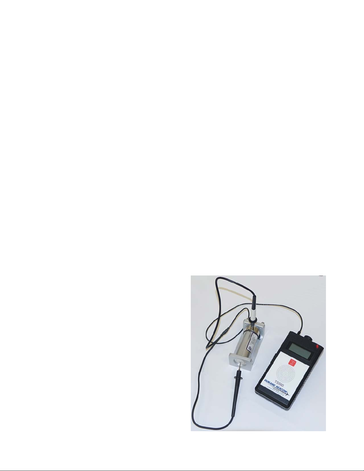
WARRANTY TEST SETS
Dukane Seacom, Inc. warrants that the Test Set (referred to as the unit) will be free from defects in
materials and workmanship, when used under normal operating conditions as determined solely by
Dukane Seacom, Inc., for a period of one (1) year from the date of shipment from Dukane Sea-
com, Inc.
As the sole remedy for breach of the foregoing warranty, Dukane Seacom, Inc. shall repair or re-
place, at Dukane Seacom, Inc.’s option, any unit, component or part thereof found defective or
nonconforming within said one (1) year period from the date of shipment. Customer shall give
Dukane Seacom, Inc. notice of any defect or nonconformity and, if so instructed by Dukane Sea-
com, Inc., customer shall, at its expense, ship the unit, component or part to Dukane Seacom, Inc..
If Dukane Seacom, Inc. determines that the unit, component or part is actually defective or non-
conforming, it shall, at its expense, ship a new or a rebuilt unit, component or part to the customer.
The customer shall be responsible to perform, at its own expense, any necessary installation work
related to any defective or nonworking unit, component or part. The functionality and operational
aspects of the unit is determined by the unit operating within the specifications and is dependent of
proper maintenance as required to be performed by the customer.
Dukane Seacom, Inc. shall not be liable for any expense or damages resulting from interruptions in
the operation of the unit.
Dukane Seacom, Inc. shall not be liable for the cost of any repairs undertaken by the customer or
any third party without Dukane Seacom, Inc. prior written authorization.
Dukane Seacom, Inc. shall not be liable for any incidental, special consequential or exemplary
damages arising out of the installation, use, testing, servicing or maintenance of any unit, compo-
nent or part. This warranty is given in lieu of all other warranties, express or implied, included the
warranties of merchantability or fitness for a particular purpose.
Dukane Seacom, Inc.’s total liability under this warranty is limited to the remanufacture or re-
placement of the unit, component or part .