Duke 155433P Guide

1
DUKE MANUFACTURING CO. 155409E
2305 N. Broadway, t. Louis, MO 63102 155433P
800-735-3853 •
••
• 314-231-1130 •
••
• 314-231-5074 FAX:
www.dukemfg.com
Duke 59-E3P
ELECTRIC HALF-SIZE
CONVECTION OVEN
POPEYE’S
Installation, Operation, Parts
& Maintenance Manual

This
This Page Intentionally Left Blank

3 of 24
INDEX
59-E3P Electrical Specifications 4
Installation Instructions
A. Qualified Personnel 5
B. Delivery & Inspection 5
C. Location of Oven 5
D. Electrical Connections 5-6
E. Ventilation 6
F. Electric Oven Assembly 6
G. Adjustments Associated with Installation 6
Control Panel 7
A. Program Parameters 8
B. Programming Instructions 8-9
C. Operation of Oven 9
D. Cool Down Operation 9
E. Emergency Back-Up System 10
F. Troubleshooting 10
G. Control Failure Diagnostics 11
Cleaning the Oven 12
Maintenance Instructions 13
A. Adjustments 13
B. Door Adjustments 13
C. Lubrication 13
D. Calibration Check 13
Repair Parts List and Corresponding Drawings 14-19
Wiring Diagram 20-22
Please supply the Model Number and the Serial Number when
ordering replacement parts or requesting service.
We recommend service by Duke A
uthorized Service
Agencies during and after the warranty period.

4 of 24
FOR YOUR SAFETY
Do not store gasoline or other flammable liquids in the vicinity of this appliance.
WARNING
Improper installation, adjustment, service or maintenance can cause property
damage, injury or death. Read all installation, operating and maintenance
instructions thoroughly before installing or servicing this appliance.
Model 59
-
E3P
ELECTRICAL SPECIFICATIONS
Power Supply Connection
TOTAL KW
VOLT
1 PHA E
3 PHA E
8.0 208 41.0 AMPS 24.0 AMPS/PH
8.0 240 36.0 AMPS 21.0 AMPS/PH

5 of 24
IN TALLATION IN TRUCTION
A. Qualified Personnel
These inst ll tion instructions re for the use of
qu lified inst ll tion nd service personnel only.
Inst ll tion or service by other th n qu lified
personnel m y result in d m ge to the oven
nd/or injury to the oper tor.
Qu lified inst ll tion personnel re those individu ls, firms,
comp nies or corpor tions which either in person or
through n gent re eng ged in nd responsible for:
•The inst ll tion of electric l wiring from the
electric meter, m in control box or service
outlet to the electric l ppli nce. Qu lified
inst ll tion personnel must be f mili r with ll
prec utions required nd h ve complied with ll
requirements of st te nd loc l uthorities
h ving jurisdiction. See: N tion l Electric l
code, ANSI/NFPA 70-1990.
B. Delivery and Inspection
Duke M nuf cturing Co., does everything within its power
to insure you receive your oven in good condition. They
re str pped down on he vy wooden skids nd surrounded
by he vy "tri-w ll" c rtons to prevent shipping d m ge.
They h ve ll been c refully inspected before they were
p ck ged nd consigned to the c rrier.
Upon Delivery of your Duke oven:
•Look over the shipping cont iner c refully
noting ny exterior d m ge on the delivery
receipt which must lso be signed by the
driver/delivery person.
•Uncr te nd check for ny d m ge which w s
not evident on the outside of the shipping
cont iner. This is c lled conce led d m ge.
The c rrier must be notified within fifteen (15)
d ys of the delivery of the oven nd the c rton,
skid nd ll p ck ging m teri ls must be
ret ined for inspection.
Duke M nuf cturing Co. c nnot ssume li bility for loss or
d m ge suffered in tr nsit. The c rrier ssumes full
responsibility for delivery in good order
when the shipment w s ccepted. However, we re
prep red to ssist you in filing ny freight cl im.
C. Location of the Oven
Proper pl nning nd pl cement of the oven will give you
the best results in terms of long term user convenience nd
s tisf ctory perform nce. We urge you to give dequ te
thought in the pl cement of your oven prior to its rriv l.
•The oven should be pl ced in n re which is
free from dr fts nd ccessible for proper
oper tion nd servicing.
•The re round the oven must be kept cle r of
combustible m teri ls. A minimum of one (1)
inch from the left or right side, three (3) inches
from the re r nd eight (8) inches from the floor
must be m int ined between the oven nd ny
combustible or non-combustible surf ce.
It is lso import nt not to obstruct the n tur l flow of
ventil tion ir if the oven is to oper te properly. Do
not pl ce ny objects on top of the oven. This oven
should not be inst lled on curb b se or se led to the
w ll. Either condition c n prevent proper ventil tion
of the blower motor. The blower motor h s therm l
protection device which will trip bec use of excessive
mbient temper tures t the side of the oven. If the
device trips continu lly, this condition should be
corrected immedi tely to void d m ging the oven
perm nently.
Before m king ny connections to the over, check the r ting
pl te to be sure the oven specific tions concur with the
volt ge nd ph se to be supplied to the oven.
The r ting pl te nd seri l number d t re loc ted behind
the motor ccess cover on the right side p nel.
D. Electrical Connections
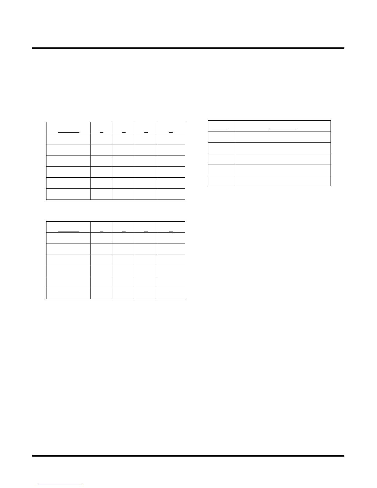
E ch section of the Duke 5/9 H lf-Size Convection Ovens
is r ted t 8.0 KW.
Your oven is supplied for connection to 208 or 240 volt,
1-ph se or 3-ph se grounded circuit. The
electric motor, indic tor lights nd control circuits re
powered intern lly nd do not h ve sep r te power
supply.
Before m king ny connections to these units, check the
r ting pl te to ssure th t the volt ge nd ph se r ting of the
oven is comp tible with the electric l supply. When
inst lling, ll ovens must be electric lly grounded in
ccord nce with loc l codes or in the bsence of loc l
codes, with the N tion l Electric l Code, ANSI/NFPA 70-
1990 (in C n d - CSA Std. C22.1).

6 of 24
Wiring di gr ms re loc ted on the inside of the motor
ccess p nel, on the right side of the oven.
E. Ventilation
Proper ventil tion is very import nt for the proper function
of your oven. A good ventil tion system will llow the oven
to function properly s well s remove unw nted v pors.
Not venting the ovens properly c n result in uns tisf ctory
b king results s well s the possibility of d m ging your
oven.
F. Oven Assembly
Before ssembling nd inst lling the oven, ple se check to
m ke sure th t ll necess ry p rts re present. In ddition to
the oven itself, there will lso be legs, feet or c sters. (For
double sections, ret ining clips, nd miscell neous
h rdw re.) Ple se check the interior of ll oven sections for
the p rts needed to ssemble nd inst ll your oven(s).
Leg Att chment (in lieu of st nd)
•Once the oven h s been removed from the
c rton, l y it on its left side (the side without the
controls).
•Hold the leg nd lign with the m tching holes
in b se nd leg fl nge. C refully st rt the 5/16
18 bolts, ( void cross-thre ding), by turning
clockwise nd tighten to the ne rest full turn. A
tot l of (12) 15/16-18 X 3/4 bolts, fl t w shers
nd lock w shers re required to secure ll legs.
•Once legs re secured, dd two (2) stor ge
shelves between the four (4) legs. Secure these
by using the 1/4-20 X 3/4 self-thre ding
screws. After completion, c refully lift the oven
to n upright position.
To level the unit, r ise or lower the djust ble feet s
required.
G. Adjustments Associated with Installation
E ch oven section nd ll its components p rts h ve been
tested thoroughly nd inspected before your oven w s
shipped from the f ctory. However, it is sometimes
necess ry to further test or djust the oven once it h s been
inst lled. Such djustments re the responsibility of the
De ler or Inst ller. These types of djustments re not
considered defects, r ther norm l nd routine p rt of the
proper inst ll tion of the equipment.
These djustments include but re not limited to:
•djustments nd rec libr tion of the controller
•djustment to the doors, leveling
•nd tightening of f steners.
No installation should be considered complete without
proper inspection and, if necessary, any adjustments by
qualified service or installation personnel.

7 of 24
FOR TECHNICAL ASSISTANCE
OR SERVICE, PLEASE CALL:
1-800-735-3853
WARNING
REPLACE WITH 10 AMP
TIME DELAY FUSES
POPEYE'S OVEN CONTROLS
Main Power ON/OFF Switch
Power On Light - Indicates elements are
on. Light will go out when set temperature
has been reached.
Display - Indicates Time and/or Temperature
Programming Buttons
Preprogrammed Buttons - for
1 through 5 different recipe
settings.
Fuses - 10 Amp Time Delay Protective

8 of 24
Gasket Groove
A. Program Parameters
This unit comes preprogr mmed from the f ctory
with the following p r meters for Menu items S1
nd S2
Menu Item S1 (Use for P r B ked Biscuits)
# Trays 1 2 3 4
Cook Time 6:00 6:00 6:00 6:00
Temperature 375° 375° 375° 375°
On Time 60 80 130 160
Duty Cycle 160 160 160 160
Offset 0 0 0 0
Shelf Position
2 1,3 1,2,3 1,2,3,4
Menu Item S2 (Use for Fresh Biscuits)
# Trays 1 2 3 4
Cook Time 10:00
10:00
10:00
10:00
Temperature 375° 375° 375° 375°
On Time 80 100 130 160
Duty Cycle 160 160 160 160
Offset 0 0 0 0
Shelf Position
2 1,3 1,2,3 1,2,3,4
Shelf position is b sed on counting from the top rung
downw rd. (See oven dr wing, p ge 9.)
For proper brownness, position e ch p n of biscuits in the
following m nner.
Push e ch p n ll the w y in until it hits the b ck
w ll, then pull it forw rd (tow rd you) one (1)
inch.
B. Programming Instructions
Progr mming the Oven Control is simple. Anytime
p r meter (one of the five cooking times, one of the five
lo d control settings, duty cycle time-b se, setpoint, or
offset) needs to be ch nged the procedure is:
•Select the desired menu item by holding down the
MENU push button nd pressing the UP/DOWN
buttons until the menu item is displ yed (The Menu
items re numbered S1 through S7)
•Press both the number 1 and number 5
start switches at the same time. This
ction tells the control th t something is to be
ch nges; the l rm will sound, nd the
number one (1) will ppe r in the displ y.
•Press one of the following buttons:
Switch To Ch nge
1 Cooking Time
2 Cooking Temper ture (Setpoint)
3 Duty Cycle On-Time
4 Duty Cycle Time B se
5 Offset
witch 1 Pressed: The displ y will show the
number “2”. Press the switch th t is to h ve its
b king time ch nged. The b king time for the
p rticul r switch will be shown in the displ y. A
b king time must be progr mmed for selections 1,
2, 3 nd 4. Use the UP/DowN buttons to ch nge
the b king time to th t desired.
NOTE: To ch nge seconds hold in the st rt
switch for one tr y, then use the UP/DOWN
switches.
Press the "Enter" switch to store the ch nge.
witch 2 Pressed: The setpoint temper ture will
be shown in the displ y.
Use the Up/Down switch to set the new setpoint.
Press the "ENTER" switch to store the new
setpoint.
witch 3 Pressed: The displ y will show the
number "2". Press the switch th t is to h ve its
lo d control ch nged. The lo d control "ON
TIME" for th t p rticul r switch will be shown on
the displ y. An "On Time" must be progr mmed
for selections 1,2, 3 nd 4.
Use the UP/DOWN switches to ch nge the lo d
control setting.
Press the "ENTER" switch to store the new lo d
control setting.
witch 4 Pressed: The Time B se will show in
the displ y.

9 of 24
NOTE: The Time Base should never be
changed unless directed to do so by America's
Favorite Chicken Corp.
Use the UP/DOWN switch to ch nge the Time
B se.
Press the "ENTER" switch to store the new TIme
B se.
witch 5 Pressed: The Offset will show in the
displ y
Use the UP/DOWN switches to ch nge the Offset
v lue.
NOTE: pressing the DOWN switch until the
displ y goes p st zero (0) will be neg tive v lues,
nd will be indic ted by lighted COLON.
Press the "ENTER" switch to store the new Offset.
NOTE: The Offset is used s me ns to c libr te
the probe temper ture to gree with the
temper ture in the center of the oven. The f ctory
setting for Offset is 30.
CONTROLLER RE ET
In r re situ tions, such s lightening strike ne r
the rest ur nt, the computer m y lose its progr m,
or become "locked up". If this should h ppen,
press the RESET switch to reset the computer, or
turn the power to the oven off nd b ck on.
Resetting the computer resynchronizes its progr m
flow.
C. Operation of the Oven
Oper tion of the computerized Auto R ck Lo d
Controller is quite simple.
Preheat: Close oven door and turn power knob
clockwise to "cook" position.
The digit l displ y will illumin te nd displ y
temper ture of 212° ( The minimum displ yed
temper ture). The mber light will lso be lit
indic ting the oven is he ting. When the oven
temper ture begins to exceed 212°, the ctu l oven
temper tures will be displ yed until the temper ture
set point h s been re ched nd the oven re dy light
h s gone off. At this point, the displ y shows 10:00
minutes, the cook time for one tr y. Alw ys keep
oven door closed until biscuits re re dy to be
lo ded onto r ck.
Baking: Open door and quickl load trays(s). ( lide
tray all the way to the back wall, then slide forward
one inch). Close door and press the switch that
corresponds to the number of trays to be loaded (1,
2, 4 or 4)
The pressed switch will illumin te, indic ting b king h s
begun. The time displ yed begins counting down.
When b ke cycle is complete, the switch you origin lly
pressed will fl sh nd the l rm sounds. Press the
fl shing switch to turn off l rm. Remove the product.
D. Cool Down Operation
The oven h s cool down fe ture to expedite cooling of
the oven interior so th t it c n be cle ned.
To initi te the cool down fe ture, turn the power
switch counter clockwise to the off position.
Open door nd turn the power switch counter
clockwise to the cool down positions. The
oven f n will only oper te, circul ting cool ir in
the oven c vity.
When the oven interior is cooled sufficiently, turn the
power switch clockwise to the off position. Begin the
d ily cle ning procedures.
1
2
3
4

10 of 24
E. Emergency Back
-
Up ystem
Your oven is equipped with n emergency b ck-up system
to be used should the computer controller ever
m lfunction.
It is intended only to be used to keep you
in operation until a service agent arrives to provide
repairs
.
Oper tion: Turn power switch to off position. Push the
toggle switch loc ted on the right ccess p nel of the oven
to the up position.
Turn power switch clockwise to cook position. The oven
will now m int in temper ture of 375° by the b ck up
thermost t. You will need to m nu lly time your b ke
cycle until the biscuits re b ked. No displ y will be
illumin ted.
Call your local authorized service agent to render
repairs as soon as possible.
F. Troubleshooting
Oven Not Heating
1. Oven he ting l mp is off.
2. Digit l displ y in the controller is not lit. (M ke
sure b ckup thermost t control switch is in the
down position.)
3. Check the 24VAC from the tr nsformer. If
volt ge is present, repl ce the controller.
4. If no volt ge, check the tr nsformer nd
tr nsformer input volt ge. M ke cert in the
correct tr nsformer input volt ge t ps re used.
Tr nsformer Prim ry Volt ge
Or nge 240-L1
Red 208-L1
WHITE 120-L1
BLACK L2
Transformer econdary Voltage
Yellow-blue 12V (pin 4 & pin3)
Yellow-blue 12V (pin 2 & pin3)
Yellow-yellow 24V (pin 4 & pin 2)
DIGITAL DI PLAY IN THE CONTROLLER I
LIT, OVEN NOT HEATING
A simple test.
1. Turn the oven off.
2. Disconnect the oven control connector to J1
on the PCB
3. Insert short insul ted jumper wire between
pins 1 nd 3 in the oven control connector.
M ke sure the wire is insul ted nd b re wire
c nnot touch ground or other met l p rts.
(CAUTION: Line volt ge present.)
4. Turn the oven on.
5. If the oven he ts up, turn the oven off,
remove the jumper from the oven control
connector, nd repl ce the oven control
connector. Check the controller's setpoint. If
the setpoint is correct, repl ce the controller.
6. If the oven does not he t up, the problem is
within the oven.
7. Turn the oven off.
8. Remove the jumper wire nd repl ce the
connector.
9. Oven He ting L mp is on. The problem is
within the oven.
OVEN TOO HOT (OVEN TAY ON)
1. Turn the oven off.
2. Disconnect the oven control connector (J1)
3. Turn the oven on.
4. If the oven he ts up, the problem is within the
oven.
5. If the oven does not he t up, turn the oven
off, nd repl ce the oven control connector on
J1, then turn the oven b ck on. Proceed to 6.
6. Press the ENTER switch to re d the oven's
temper ture.
7. Indic ted temper ture is obviously less th n it
should be.
8. The thermocouple c ble m y be shorted, or,
9. The controller m y be defective.
10. Repl ce the temper ture probe.
11. If the temper ture now indic tes the correct
temper ture, the problem w s the temper ture
probe.
12. If the temper ture still indic tes lower th n
expected, repl ce the controller.

11 of 24
OVEN NOT RECOVERING WHEN
BAKING
1. Check the Duty Cycle ON-TIME setting.
2. Me sure the ctu l ON-TIME nd OFF-
TIME with stopw tch or use the second
h nd of wristw tch or clock to see if the
oven is being controlled properly.
3. If the oven turns on nd off t the proper
times, the f ult is within the oven. Check
mp dr w to e ch element. Be cert in oven is
supplied with proper volt ge. (240 volt
elements on 208 volt power supply, for
inst nce.)
4. If the oven does not turn on nd off t the
proper times, repl ce the controller.
BI CUIT TOO DARK (OVER BAKED)
1. Reduce the duty Cycle ON_TIME until the
biscuits re the correct brownness.
BI CUIT TOO LIGHT (OVER BAKED)
1. Incre se the Duty Cycle ON-TIME until the
biscuits re the correct brownness.
G. Control Failure Diagnostics
There re two types of f ilures th t will shut down the oven
nd displ y numbers th t indic te the c use of the trouble:
1.Temperature Probe Opens
Should the controller's probe/c ble become n
open circuit following occur:
A. The oven is turned off
B. The l rm begins beeping
C. The displ y will show four (4) nines (9999)
Press one of the five START switches to turn off
the l rm.
Repl ce the probe/c ble.
2. Oven tays On Too Long
If the oven st ys ON for over fifteen (15) minutes,
nd this ON condition is c used by the controller
receiving n improper temper ture sign l, the
following will occur.
A. The oven is turned off.
B. The l rm begins beeping
C. The displ y will show four (4) sevens (7777)
Press one of the START switches to turn off the
l rm.
Check the probe's temper ture by pressing the
ENTER switch. If the indic ted temper ture is
less th n the ctu l oven temper ture, the probe
c ble is prob bly shorted, c using second
thermocouple t lower temper ture. Repl ce the
thermost t probe/c ble.
If the temper ture shown in the displ y is bout
the s me s th t of the oven's, the problem is
prob bly the Controller. Repl ce the controller.
Cleaning of the Oven
The st inless steel on your oven c n be kept cle n with
good st inless steel cle ner, m n of which re on the
m rket. The p inted surf ces should be wiped cle n
regul rly with MILD detergent. Moisten cloth nd
wipe down the oven while it is COLD. Wiping down n
oven while it is hot will c use stre king nd otherwise
uns tisf ctory results. Once the oven is cle n, it c n be
wiped down with light oil.
Porcel in oven interiors should be cle ned regul rly using
degre sing gent. For he vier deposits commerci l
oven cle ner such s Dow Oven Cle ner, E sy-Off, or
Mr. Muscle c n be used. C re must be t ken to prevent
these lk line-type cle ners from coming in cont ct with
ny luminized steel surf ces in the oven, including the
blower wheel.
The r cks nd r ck supports c n be removed nd so ked
in solution of mmoni nd w ter.
M ke cert in th t ll p rts re thoroughly rinsed before
returning to use.
NOTE: Never steam clean or hose down with
water. Electric component will fail due to
moisture.

12 of 24
DAILY
CLEANING INSTRUCTIONS
1. Clean the porcelain interior using a degreasing agent. For heavier deposits a
commercial oven cleaner such as Dow Oven Cleaner, Easy-Off or Mr. Muscle can
be used.
2. Clean exterior painted surfaces with warm water and a mild detergent. Moisten a
cloth and wipe down the oven while it is COLD.
3. Clean Stainless steel on the oven with a good stainless steel cleaner.
4. Make sure that all parts are thoroughly rinsed before returning to use.
!Caution!
Do not use caustic cleaners, acids, ammonia products or abrasive cleaners or cloths.
These can damage the stainless steel and door gaskets.
Never steam clean or hose down with water. Electric component will fail due to
moisture
.
WEEKLY
The racks and rack supports can be removed and soaked in a solution of ammonia and
water. Make certain that all parts are thoroughly rinsed before returning to use.
MONTHLY
1.
Check door handle screws for tightness.
THREE MONTHS
1. Check the door gasket seal on the oven and proofer for leaks. See the section on
Door Adjustments and Gasket Maintenance for help.
SIX MONTHS
Before performing control panel maintenance, main distribution panel circuit breaker for
oven must be turned off. This maintenance should be preformed by Qualified
Maintenance Personnel only. Read and follow the manufacturers instructions, Material
Safety Data Sheets (MSDS) and Wrokplace Hazardous Material Information Systems
(WHMIS) before using any type of cleaning chemicals, degreaser, etc.
1. Clean Control Panel Mylar using a mild degreaser and water.
2. Clean Control Compartment Interior – Use commercial electronic component
spray (if necessary) to de-grease the control compartment (see Note above).
3. Inspect/Replace any or all wiring which is saturated with oil.
4. Inspect Oven Door-lubricate door plunger assembly and strike plate with food
grade high temperature lubricant such as Lubriplate FGL-1, adjust door as
necessary
5. Inspect Element Wire Connections-take amp readings of elements.
6. Inspect Blower Motor – Degrease as necessary
7. Inspect Blower Wheel – Clean with ammonia and water solution.
8. Inspect Back-up Thermostat – Check calibration.

13 of 24
MAINTENANCE IN TRUCTION
These m inten nce instructions re for the use of qu lified
service personnel only. Service by other th n qu lified
personnel m y result in d m ge to the oven nd/or injury to
the oper tor.
Qu lified service personnel re those individu ls, firms,
comp nies or corpor tions which either in person or through
n gent re eng ged in nd responsible for rep ir or
servicing of commerci l food prep r tion equipment, who
re experienced in such work, f mili r with ll prec utions
required, nd h ve complied with ll requirements of st te
nd loc l uthorities h ving jurisdiction.
If you should require ssist nce in the selection of qu lified
service gency, ple se cont ct Duke M nuf cturing Co.'s
Service Dep rtment t 800-735-3853.
A
. Adjustments
Quite often m lfunctions which re ttributed to defects m y
be rep ired by djusting cert in p rts r ther th n repl cing
them.
B. Door Adjustment
The door switch is loc ted behind the lower front cover, on
the right or left side. (Fig.1) The door switch (A) is ctiv ted
by c m (B) which is mounted to the door's hinge pin with
set screw. Position the door so it is ne rly closed but not
l tched. To djust the c m:
•Loosen the set screw nd rot te the c m until you
he r the switch click.
•Tighten the set screw in the c m.
•Test the door to m ke cert in the switch will m ke
cont ct with the doors closed.
•Repl ce the comp rtment cover.
C. Lubrication
The door plunger ssembly requires periodic lubric tion by
the oper tor to ensure smooth, trouble-free oper tion.
Applic tion of Food Gr de High Temper ture Lubric nt
such s Lubripl te FGL-1 is recommended t le st
bimonthly. Apply lubric nt to the plunger nd strike pl te
sp ringly. If necess ry, lubric te t more frequent interv ls.
D. Back-up thermostat calibration check:
•Turn the oven on by turning the Power Switch to
the ON position.
•Open the doors nd pl ce thermocouple in the
center of the middle oven r ck. A reli ble mercury-
type thermometer c n be substituted if pyrometer
is not v il ble.
•Turn the power switch to the off position.
•Turn the thermost t di l to 375ºF (177ºC). Allow
the oven to prehe t ½ hour.
•Note the m ximum nd minimum temper tures
through sever l cycles.
•If the re ding on the pyrometer (or thermometer) is
less th n 10ºF different from the setting of the
thermost t, no djustment is needed. If this re ding
is more th n 10ºF, proceed with c libr tion
procedure.
To Recalibrate:
•Remove the thermost t knob by loosening the
setscrew nd pull the knob forw rd. T ke c re not
to rot te the thermost t stem, which will ch nge the
setting.
•With very sm ll screwdriver, turn the screw
loc ted in the bottom of the hollow of the stem
clockwise to lower the temper ture of
counterclockwise to r ise the temper ture. DO
NOT llow the stem of the thermost t to rot te s
your turn the screw.
Caution: Maximum turn of screw “A” is 1-1/2
turns – clockwise or counter-clockwiase.
This thermost t is direct- cting (opens on temper ture rise)
device.

14 of 24
Model 59-E3P Half-Size Electric Convection Oven
Repair Parts List
Item # Part # Description
1 156333 Mylar
2 153142 Knob, control
3 153204 Light, oven ready, 208v/240v
4 153200 Holder, fuse
5 153201 Fuse, 10 amp
6 153460 Switch, rotary
7 155301 Transformer, 208/240V
153358* Transformer, 480/240V 1KVA
8 600108 Controller
9 155304 Probe
10 153210 Terminal block
11 153156 Contactor, 208v/240v, 3-pole, 50 amp
12 153034 Motor, 208/240v, 1-speed
13 153093 Fan Wheel
14 155079 Element, outer, 240v, 2.667 KW
14 155076 Element, outer, 208v, 2.667 KW
15 155078 Element, center, 240v, 2.667 KW
15 155075 Element, center, 208v, 2.667 KW
16 155077 Element, inner, 240v, 2.667 KW
16 155074 Element, inner, 208v, 2.667 KW
17 155113 Support, rack, oven
18 155114 Rack, oven
19 155404 Handle, door
20 155451* door, with glass hinged right
155454 door, with glass hinged left
21 155132 Glass only
22 155107 Actuator, door switch
23 148077 Switch, micro, door
24 153056 Bearing, door
25 155007 Gasket, door top
26 155006 Gasket, door bottom
27 155008 Gasket, door side (2)
28 153416 Catch, door
29 153801 Latch, roller assembly
30 155318 Switch, toggle, back up system
31 149403 Thermostat, backup
32 153142 Knob, backup thermostat
33 153588 Overlay, backup thermostat
34 600100 Kit, Flue Guard (Optional)
35 155125 Bracket, Stacking
* NOT SHOWN
Diagrams of parts on following pages

15 of 24
MODEL 59E3P OVEN

16 of 24
INTERIOR OVEN COMPONENTS

17 of 24
MODEL 59-E3P DOOR ASSEMBLY

18 of 24
OVEN BACKUP THERMOSTAT SYSTEM

19 of 24
FLUE GUARD
1.) On rear of top oven remove two existing
screws that are located at the lower right
hand corner.
2.) On rear of bottom oven remove two
existing screws that are located at the
upper right hand corner.
3.) Install stacking bracket using the
existing screws as shown in figure.
4.) Repeat steps to install 2
nd
stacking
bracket on left hand side.
Securing
Double Stacked Ovens
35

20 of 24
KX THERMOSTAT
10 BK
11 BK
TIME DELAY
10 AMP
FUSES
6 RD
20 RD
19 BK
15 PIN
PLUG/RECEPTACLE
CONNECTOR
11 BK
7 G
9 BK
10 BK
5 BK
7 G
6 RD
11 BK
10 BK
9 BK
5 BK
6 RD
7 G
9 BK
CONTROL PANEL
19 BK
POWER
PROBE
11 BK
4 BK
1 RD
CCSI DIGITAL
COOK/TIME
CONTROL
HEAT
DEMAND
COOK
LIGHT
POWER
SWITCH
18 BK
11 BK
31 BK
3 BK
10 BK
N
3
4 BK
2 4
L1
1
REAR VIEW
32 BK
3 BK
BLUE
YELLOW
YELLOW
9 BK
3 BK
4 BK
1 RD
10 BK
19 BK
20 RD
3 BK
4 BK
1 RD
ORANGE FOR 240V.
RED FOR 208V. OR
TO TRANSFORMER
20 RD CONNECTS
NOTE: WIRE NO.,
TRANSFORMER
BLACK/LINE
ORANGE/240V.
RED/208V.
RTD PROBE
20 RD
9 BK
9 BK
3 BK
10 BK
31 BK
33 BK
9 BK
SWITCH
TOGGLE
32 BK
DOOR
SWITCH
NO
NC
C
8 BK
8 BK
C
NO
3 BK
31 BK
Table of contents
Other Duke Oven manuals