Duke TSC3-6/18 User manual

This manual is Copyright © 2022 Duke Manufacturing Co. All rights reserved.
Reproduction without written permission is prohibited. Duke is a registered
trademark of the Duke Manufacturing Co.
CAUTION: Please read this manual completely before attempting
to install, operate or service this equipment
WARNING: Cancer and Reproductive Harm -
www.p65warnings.ca.gov
Installation and
Operation Manual
Proofer Oven with Touch
screen Controls (TSC)
Models:
TSC3-6/18
TSC3-3/9
P/N 120085
Rev M 08/11/2022

TABLE OF CONTENTS
INTRODUCTION ..................................................................................................................................2
IMPORTANT SAFETY INSTRUCTIONS ...........................................................................................3
SPECIFICATIONS................................................................................................................................5
MAIN FEATURES.................................................................................................................................6
INSTALLATION ..................................................................................................................................10
OPERATING INSTRUCTIONS..........................................................................................................15
CARE AND CLEANING.....................................................................................................................20
PROGRAMMING CONTROLS..........................................................................................................21
TROUBLESHOOTING ......................................................................................................................24
WIRING DIAGRAM ............................................................................................................................25
INTRODUCTION
These appliances are intended to be used for commercial applications, for example in kitchens of
restaurants, canteens, hospitals and in commercial enterprises such as bakeries etc., but not for continuous
mass production of food.
The Duke TSC (Touch Screen Control) Proofer Oven was developed in response to the Customer's need
for uniform baking capabilities and to provide consistently high quality just-baked bread.The Duke
Proofer Oven utilizes Duke’s unique directional convection airow technology that provides even heat
distribution and a uniform bake without the need for turning pans during the bake cycle. This enhances the
quality and consistency of the baked products, reduces food scrap and waste while simplifying operating
process.
The low prole oven won’t block the view of menu boards and will easily roll through a standard height
door. The oven and proofer doors are eld reversible with a drip channel on the proofer door, which
prevents water from dripping on the oor.
Full-width doors on the oven and proofer help to display and merchandise fresh baked bread to the
customer.
The full-width oven and proofer cavity will accept standard half-size or full-size sheet pans.
The TSC models feature a simple color LCD touch screen control that allows users to quickly select from
pre-programmed recipes for baking and proong. Advanced features are also included for custom recipes
plus user accessible information for operating instructions and maintenance information.

IMPORTANT SAFETY INSTRUCTIONS
Throughout this manual, you will nd the following safety words and symbols that signify
important safety risks with regards to operating or maintaining the equipment.
Indicates a hazardous situation which, if not avoided, could
result in death or serious injury.
CAUTION
Indicates a hazardous situation which, if not avoided, could
result in minor or moderate injury.
CAUTION
Indicates Important Information
Indicates electrical shock hazard which, if not avoided, could
result in death or serious injury and/or equipment damage.
Indicates hot surface which, if not avoided, could result in
minor or moderate injury. Specically, risk of burn from
heating elements.
Indicates rotating fan blade hazard which, if not avoided,
could result in
In addition to the warnings and cautions in this manual, use the following guidelines for
safe operation of the unit.
• Read all instructions before using equipment.
• Install or locate the equipment only for its intended use as described in this manual.
• Do not use corrosive chemicals on this equipment.
• This equipment must be serviced by qualied personnel only. Contact the nearest
Duke authorized service facility for adjustment or repair.
• Do not block or cover any openings on the unit.

4
Installation and Operation of: DUKE TSC3 Proofer Oven with Touch Screen Controls
The following warnings and cautions appear throughout this manual and should be
carefully observed.
• Turn the unit o, disconnect the power source and allow unit to cool down before
performing any service or maintenance on the unit.
• The unit must be grounded according to local electrical codes to prevent the possibility
of electrical shock. Models supplied with a cord and plug require a grounded receptacle
with dedicated electrical lines, protected by fuses or circuit breaker of the proper rating,
in accordance with all applicable regulations.
• Disposal of the unit must be in accordance with local environmental codes and/or any
other applicable codes.
• Properly rated all poles mains protection and earthing compliance with local electric
codes are required for safe operation of this unit.
• Secure unit to a wall with the wall mounting brackets provided to prevent tipping.
• Install the Restraining Device Kit to prevent damage to mains supply connections.
• Water supply connections to the unit must comply with local plumbing code and/or
standards.
• If the equipment is moved, make sure that all utility connections are properly
disconnected. If the equipment is returned to its original position, make sure that any
retention devices and utility connections are properly connected.
• Turn the Control Power Switch o and disconnect external all poles mains supply then
allow unit to cool down before performing any service, maintenance or cleaning on the
unit.
• When working on this equipment, observe precautions in this manual or labels attached
to or shipped with this equipment and other safety precautions that may apply.
• Be careful of a possible slippery oor adjacent to this equipment.
• Always use sucient number of trained and qualied personnel to move the appliance.
Do not tilt. Appliance can tip over when being moved over an uneven oor or threshold
and cause serious injury. Always apply caster brakes when not being moved.
• This appliance is not intended for use by persons (including children) with reduced
physical, sensory, or mental capabilities, or lack of experience and knowledge, unless
they have been given supervision or instruction concerning use of the appliance by a
person responsible for their safety.

5
Installation and Operation of: DUKE TSC3 Proofer Oven with Touch Screen Controls
SPECIFICATIONS
Patent Pending -
Model TSCM, TSC3
Line Ratings - TSCM & TSC3 Proofer Oven with Touch Screen Control
Line Supply
Voltage (V)
Line Supply
Frequency (Hz)
Line Phase
Conguration
Total Maximum
Line Power
Watts (W)
Total Maximum
Line Current
Amps (A)
208 60 Single Phase 6 650 32
208 60 3 ~ 6 650 32 ▲1
240 50 & 60 Single Phase 7 200 30
240 60 3 ~ 7 200 30 ▲1
380 50 & 60 3N ~ 6 100 30 ▲2
400 50 3N ~ 6 600 30 ▲2
415 50 & 60 3N ~ 7 200 30 ▲2
S1 L1<15A, L2<15A, L3<25A S2: L1<15A, L2<15A, L3<15A, N = Comm
Unit Weight: 580 lbs / 263 kg
Shipping Weight:
Carton Box
630 lbs / 286 kg
Shipping Weight:
Wooden Crate
720 lbs / 327 kg
Compliance Declaration - TSC3,TSC-M Proofer Oven with Touch Screen Control
Standard: UL197 File: KNGT.E17421
FCC Part 15 Subpart B:2017
Standard: CSA-C22.2 No. 109
ICES-003:2017 File: KNGT7.E17421
Standard: ANSI / NSF 4 File: TSQT.E157479
IPX4
Directive 2006/95/EC:
IEC 60335 1:2010, +A1:2012, A1:2013
IEC 60335 2 42:2002, + A1:2008
IEC 60529 ED.2.2 B:2013
EN60335 -1:2012 + 11:2014
EN 60335-2-42:2003 + A11:2008, + A11:2012
Directive 89/336/EEC:
EN62233:2008
EN61000-6-3:2007
EN55014-2:2015
EN61000-6-2:2016
EN61000-6-4:2011
Directive 2014/53/EU:
EN 301 489-1:2016
EN 301 489-17:2009
WEEE Directive 2002/96/EC
RoHS 2011/65/EU

6
Installation and Operation of: DUKE TSC3 Proofer Oven with Touch Screen Controls
MAIN FEATURES
Figure: Main Features
LOW VOLTAGE
LIGHTING SYSTEM
12V HALOGEN LAMP
10WATT MAX
CONVECTION
OVEN
3 SHELVES
TOUCH SCREEN
CONTROL PANEL
PROOFER
9 SHELVES
DRIP PAN
DOORS AND
HINGES
ARE REVERSIBLE
CIRCUIT
BREAKER
HIGH LIMIT
PROTECTOR
COOL TOUCH
AIR- WASH
DOOR
POWER SWITCH
DOORS AND
HINGES
ARE REVERSIBLE
ETHERNET PORT
USB PORT

7
Installation and Operation of: DUKE TSC3 Proofer Oven with Touch Screen Controls
1826.4mm
(71.90in)
(42.78in)
1086.6mm
(37.22in)
945.4mm
1975.6mm
(77.78in)
2006.2mm
(78.985in)
1826.4mm
(71.906in)
1086.6mm
(42.781in)
945.4 mm
(37.22 in.)
2027.7mm
(79.83in)
Model
Overall
Depth
Overall
Height
Overall
Width
in mm in mm in mm
Domestic 30.34 770.6 77.78 1975.6 37.22 945.3
International 30.34 77.06 79.83 2027.7 37.22 94.53
DOMESTIC
FRONT VIEW DIMEMSIONS
INTERNATIONAL CE
FRONT VIEW DIMENSIONS

8
Installation and Operation of: DUKE TSC3 Proofer Oven with Touch Screen Controls
SIDE VIEW DIMENSIONS
(3.62in)
(30.34in)
770.5mm
665.1mm
(26.19in)
92mm
159.8mm
(6.30in)
Light Circuit
Breaker
High Limit
Reset Button
Side Panel

9
Installation and Operation of: DUKE TSC3 Proofer Oven with Touch Screen Controls
BACK VIEW DIMENSIONS
919mm
(18.61in)
INLET
472.7mm
1149.2mm
ELECTRICAL
734.5mm
246.8mm
BACK FLOW VALVE
W/O OPTIONAL
(45.24in)
(36.18in)
585.2mm
(23.04in)
(9.72in)
(28.92in) BACK FLOW VALVEW/O OPTIONAL
WATER INLET
W/OPTIONAL
BACK FLOW VALVE
700.6mm
WATER OUTLET
W/OPTIONAL BACK FLOW VALVE
(27.58in)

10
Installation and Operation of: DUKE TSC3 Proofer Oven with Touch Screen Controls
INSTALLATION
UNPACKING UNIT
Inspect the shipping carton and/or container,
carefully noting any exterior damage on the
delivery receipt; also note any damage not evident
on the outside of the shipping container (concealed
damage). Contact the carrier immediately and le a
damage claim with them. Save all packing materials
when ling a claim. Freight damage claims are the
responsibility of the purchaser and are not covered
by the warranty.
• Follow the instructions on the Carton Box for
unpacking the unit.
• Inspect unit for damage such as, broken glass,
etc.
• Report any dents or breakage to source of
purchase immediately.
• Do not attempt to use unit if damaged.
• Remove all materials from unit interior.
• If unit has been stored in extremely cold area,
wait a few hours before connecting power.
UNIT PLACEMENT
• Do not install unit next to source of heat, such
as deep fryer, etc.
• Install unit on level surface oor.
• Minimum Clearance of 6" (152mm) must
be maintained between the unit and any
combustible substance.
• Either side of the unit must remain open for
proper airow for electrical component cooling.
The rear of the unit and one side may be
installed without clearance.
ELECTRICAL AND SUPPLY CONNECTIONS
Connection of the unit to the mains supply
MUST be performed by an authorized person
in accordance with codes, standards, and laws
governing the installation site using properly rated
all poles mains protection, full disconnection under
over voltage category III, safety ground earthing,
and shall be a minimum of 48" (1.2 meter) long to
allow the equipment to be moved for cleaning.
USA and non-EU Countries must use exible
conduit within variances that may be required by
local electric codes or regulations.
All International installations must use IEC 60245
IEC 66, HO7RN-F, minimum 5G 2,5mm, 5G4.0mm
maximum exible cordage.
For 1~ appliances use minimum 3G 4.0mm, 3G
6.0mm maximum exible cordage.
The Mains Supply safety / earth ground wire must
be longer than mains conductors at the unit's
interconnections to prevent stress under pull.
Contact Duke for service of IVS (Integrated
Ventilation System) HO5RN supply interconnection.
EXTERNAL EQUIPOTENTIAL
Terminal provides a connection for bonding to
equipment enclosure.
WATER SUPPLY CONNECTION
This equipment must be installed in accordance
with all applicable federal, state, and/or local
plumbing codes having jurisdiction.
The water inlet utilizes ¼” (6.35mm), OD plastic
tubing. Install the tubing in a manner to ensure
there are no kinks, strains, or tight bends. Leave
sucient length to allow unit movement for service
and cleaning.
The tubing should be cut square and be free of any
deformations at the connection points. All burrs
and sharp edges should be removed for proper
connection.
Insert the tubing through the compression tting
with the threads pointing towards the end of the
tubing.
Push the tubing into the tting as far as it will go
and tighten the nut with a ½” (12.7mm), wrench.
Do not over-tighten the nut. If leaks occur, further
tighten the tting until the leakage stops.
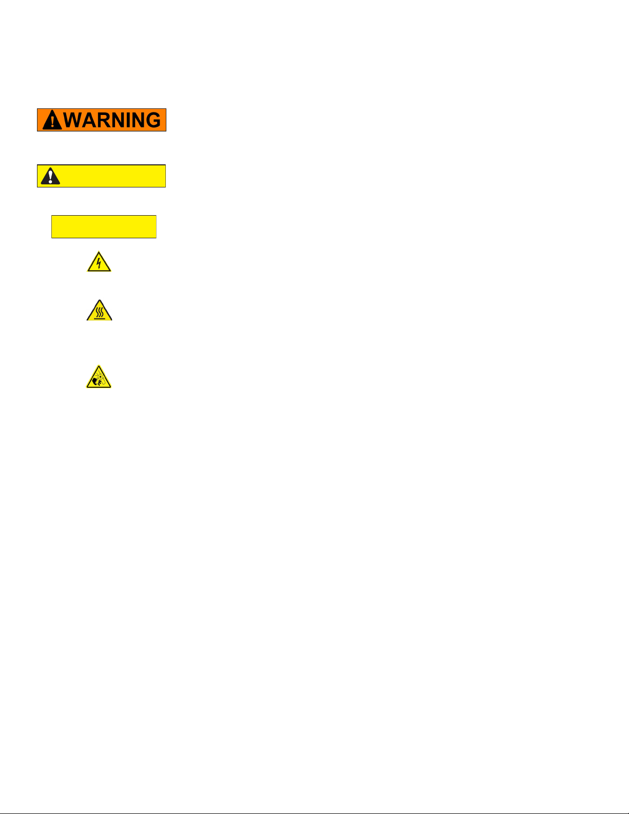
ELECTRICAL SHOCK HAZARD UNIT MUST BE
SAFETY GROUNDED, EARTHED.
DO NOT MODIFY OR DEFEAT ELECTRICAL
CONNECTIONS

11
Installation and Operation of: DUKE TSC3 Proofer Oven with Touch Screen Controls
Figure: Restraining Device Kit (Part # 153586)
HAZARDOUS VOLTAGE RISK OF ELECTRIC SHOCK
DISCONNECTPOWERTOSERVICECOMPARTMENT
THIS RESTRAINING DEVICE MUST ALWAYS
BE CONNECTED WHEN THE APPLIANCE IS IN
SERVICE. DISCONNECT ONLY FOR SERVICING
AND/OR CLEANING,THEN RECONNECTWHEN
THE APPLIANCE HAS BEEN RETURNED TO
ITS NORMAL POSITION.
INSTALLATION
1. This unit can be converted to other mains
supply congurations by Duke Manufacturing
approved service personnel. Call Duke Service
Department for action if electrical rating tag
information is not compatible with the available
mains supply.
2. This unit is supplied with the national
and international specied water supply
interconnection. Back ow prevention
protection is optionally supplied as a factory
installed option or as an add-on kit. Local
regulation variances or additional requirements
must be evaluated prior to installation. New
water supply line interconnection must be used
when installing this unit.
Maximum / minimum supply pressure
specication is 65PSI (448kPa) / 40PSI (275kPa)
for all system plumbing components. See
INSTALLATION OF WATER FILTER section prior
to water supply interconnect.
3. This appliance must be secured to building
structure. A restraining device kit (#153586)
provided with the unit limits the movement of
the appliance without transmitting stress to the
mains supply. Installation instructions are in the
kit.
4. IMPORTANT: A minimum clearance of
6"(152mm) from the top of unit to the ceiling
must be provided. Unit may be installed with
minimal clearance on one side and rear of the
cabinet.
5. Check the swing of the door. The hinge side can
be changed by referring to the Reversing Oven
Door Swing Direction section of this manual.
6. Check the door seal and make sure both doors
close completely. If they do not close and seal
properly, refer to the Door Gasket Adjustment
section of this manual.
INSTALLATION continued
7. Place the wire racks in the oven and proofer.
8. Unit can be mechanically attached to wall using
optional wall-mounting brackets. Optional
wall-mounting brackets are not required for safe
operation of the unit. Refer to Installation of
Wall Brackets section of this manual for the
instructions on Installation of Wall Brackets to
the wall.

12
Installation and Operation of: DUKE TSC3 Proofer Oven with Touch Screen Controls
This equipment is intended to be connected to a
potable water supply system under pressure and is
to be installed with adequate backow protection
to comply with all applicable federal, state, and
local codes.
Water supply pressure for proper operation shall be:
Minimum 40 PSIG(275 kPa)
Maximum 65 PSIG(448 kPa)
measured at water line inlet to the equipment.
If so equipped, regular maintenance is required to
replace the water lter cartridge at least once per
year, and to clean the inlet water screen at least
once per year. Consult state/local codes for any
additional requirements.
INSTALLATION OF WATER FILTER
Install new lter by removing sanitary cap from top
of cartridge, ensure two black O-rings are in place,
then lift up into lter head and rotate cartridge
1/4 turn counter clockwise until it comes to a complete
stop. Flush 2 gallons (7.6 Liters) of water through the
new lter before using proofer to purge air from lter.
Remove hose from bottom of proofer by loosening
the compression nut at the disconnect tting
and pull hose out. Place hose over container and
turn on water. It will take a minute for the lter
to ll before water ows out of hose into container.
once lter is ushed with 2 gallons (7.6 Liters) of water,
turn o water supply again, insert hose into water line
disconnect, tighten compression nut and turn
water supply on again. Check for leaks at
connection ttings.
Patent(s) Pending
TECHNICAL DESCRIPTION AND APPLICATION NOTES FOR TSC PROOFER OVEN BACK FLOW
PREVENTER SYSTEM
Check with your local authority having jurisdiction
regarding approvals for connecting the Duke TSC
Proofer Oven to a potable water supply before
making any plumbing connections. Plumbing code
requirements vary, but European Union (CE) and
other jurisdictions require a back ow prevention
device that is factory-installed or available as a
kit (P/N 600187). The back ow prevention device
used on Duke TSC Proofer Ovens protects water
supply systems by preventing the reverse ow of
non-potable water into the potable domestic water
system. The device consists of two independently
acting check valves, internally force-loaded to a
normally closed position and designed/constructed
to operate under intermittent or continuous
pressure conditions. The two main components of
the Duke back ow preventer system are:
• Dual Check Valve type back ow preventer that
conforms to ANSI/ASSE standard #1024 and is
CSA standard B64.6 certied.
• Inlet water strainer equipped with 100-mesh
screen and installed up stream of the back ow
preventer. The screen is conveniently located
on the rear panel of the proofer, below the back
ow preventer, for easy access during cleaning/
replacement.
INSTALLATION continued

13
Installation and Operation of: DUKE TSC3 Proofer Oven with Touch Screen Controls
INSTALLATION OF WATER FILTER
1. Install new lter by removing sanitary cap from
top of cartridge, insure two black O rings are
in place, then lift up into lter head and rotate
cartridge 1/4 turn counter clockwise until it
comes to a complete stop.
2. Flush 2 gallons (7.5 Liters), of water through the
new lter before using proofer to purge air from
lter. Remove hose from bottom of proofer
by loosening the compression nut at the
disconnect tting and pull hose out. Place hose
over container and turn on water. It will take a
minute for the lter to ll before water ows out
of hose into container.
3. Once lter is ushed with 2 (7.5 Liters), gallons
of water, turn o water supply again, insert hose
into water line disconnect, tighten compression
nut and turn water supply on again. Check for
leaks at connection ttings.
Figure: Water Filter
(Flushing 2 gallons (7.5 Liters), of water)
Water Line Disconnect Fitting
Factory Installed or Kit
Back ow Preventer
Inlet Water Connection
Inlet Water Connection Point
Water Connection if
Back ow Preventer
is Not Required
INSTALLATION OF WALLBRACKETS
NOTE: Verify interconnections and function prior
to installing optional wall brackets
1. Mount the Wall Mounting Brackets with screws
provided with the Proofer Oven.
2. Extend the Wall Mounting Bracket towards the
wall by sliding it through the slot provided but
do not tighten the screws.
3. Mark the Wall and Drill holes for the wall
anchors.
4. Insert the wall anchors into the holes.
5. Position the Wall Mounting Brackets against the
wall.
6. Insert the screws into the Wall Mounting
Bracket.
7. Ensure that the Brackets are rmly against the
wall and tighten the screws securely.
Wall
Wall
Hole drilled in wall
for fixing bracket
Wall Mounting
Bracket
Figure: Wall Mounting Bracket
INSTALLATION continued

14
Installation and Operation of: DUKE TSC3 Proofer Oven with Touch Screen Controls
PROOFER OVEN STARTUP
ELECTRICAL SHOCK HAZARD.
TASKS MUST BE PERFORMED BY A QUALIFIED
SERVICE TECHNICIAN OR ELECTRICIAN.
1. Have a qualied service technician or electrician
connect the Proofer Oven to the power supply.
2. Turn power on to the unit with the power switch
on the left side of the unit. Boot Screen is displayed
and automatically transitions to the Main Screen.
3. Turn the oven and proofer ON by touching the
and buttons located at the left of
the touch screen. The Oven, Proofer and Recipe
Buttons will turn to BLUE background. The
Oven and Proofer lights will turn on and start
preheating.
Figure: Main Screen
4. VerifyHumidicationoftheproofer.Humidication
will begin automatically. Humidity level will be
controlled according to user-selected %RH set
point.
5. Check the door seals and make sure both doors
close completely.
6. If the unit does not power up correctly or if the
doors do not close and seal properly, call Duke
for assistance.
OPERATING INSTRUCTIONS
370 F

15
Installation and Operation of: DUKE TSC3 Proofer Oven with Touch Screen Controls
AUDIBLE ALARMS
The Oven/Proofer has various audible alarms.
1 chirp Keystroke acknowledgement
3 short chirps Oven and Proofer up-to-temperature notication
4 beeps (Continuous until cleared) Oven door open alarm
3 long chirps Proofer stagger load alarm
3 beeps (Continuous until cleared) Proofer end of cycle
2 beeps (Continuous until cleared) Oven end of cycle
1 beep/2 beep pattern (Continuous until cleared) Seasoning Alarm
OPERATING INSTRUCTIONS
Touch Screen Denitions
Main Tool Bar Screen Sleep Button* Info Button
Oven Recipe Information Bar
Recipe
Temp
Recipe
Time
Proofer Recipe Information Bar
Recipe
Humidity
Recipe
Temp
Recipe
Time
Page
Forward
Page Back
Follow instructions on screen.
Touch to start Dry-Out cycle at end
of use for each day.
Recipe
Name
With oven door open, DOOR OPEN
will ash in the Main Tool Bar and
oven icon background is orange.
Door Open
Power Button
or Back
* Screen Sleep Button only available when Oven and Proofer are o
370 F
370 F
370 F

16
Installation and Operation of: DUKE TSC3 Proofer Oven with Touch Screen Controls
1. Turn power on to the unit with the power switch
ontheleftside oftheunit. BootScreenisdisplayed
and automatically transitions to the Main Screen.
2. Turn the Oven and Proofer ON by touching the
and buttons located at the left of
the touch screen. The Oven, Proofer and Recipe
Buttons will turn to BLUE background. The
Oven and Proofer lights will turn on and start
preheating.
3. Check to make sure that the oven and proofer
fans are running.
4. Open the oven door; the oven fan should stop.
5. Close the door; the fan should resume.
6. Allow the oven and proofer to pre-heat for at
least 30 minutes. An audible alarm will sound
(3 short chirps) when the oven and/or proofer
reach the ready state. Your Duke Proofer Oven is
now ready to operate.
If there are any problems refer to the Trouble
Shooting section of this manual.
DAILY OVEN/PROOFER STARTUP
1. Turn the proofer ON by touching the
button or the desired RECIPE button. The
Proofer and Recipe Buttons will turn to BLUE
background. The Proofer lights will turn on and
proofer will start preheating.
PROOFER OPERATING INSTRUCTIONS
Figure: Proofer Main Screen
2. Proofer will preheat for 10 minutes after
reaching set point to ensure proper proong
conditions. An audible alarm will sound (3
short chirps) when the proofer reaches the
ready state.
Figure: Proofer Starting Up Screen
(10 Minute Starting Up Timer)
Figure: Main Screen
Figure: Proofer Starting Up Screen
(If under temperature set point)
OPERATING INSTRUCTIONS continued
370 F

17
Installation and Operation of: DUKE TSC3 Proofer Oven with Touch Screen Controls
4. Watch for a light fog to appear on the interior
door glass; the proofer is ready to be loaded
with dough.
5. Increase humidity, if door glass does not fog as
the humidity is set too low; press button of
the (Relative Humidity). The RH% will
increase on the Proofer Recipe Information Bar.
6. Decrease humidity if water is running down
door glass as the humidity is set too high; press
button of the (Relative Humidity).
The RH% will decrease on the Proofer Recipe
Information Bar.
7. Load the rst proofer section with dough and
touch UPPER, MIDDLE or LOWER Start Timer
, depending on where dough is loaded.
This will prevent over-proong of the dough
remaining in proofer after the rst load has
been moved to the oven. The remaining time
will be displayed in the button area and the
progress bar will change to visually show
elapsed and remaining proof time.
Since the proofer can hold more pans than the
oven can bake, an alarm beeps and LOAD NEXT
TRAY is displayed in the Main Tool Bar 1/3rd of
the time thru the proofer cycle so that loads
can be staggered. Load the next proofer section
with dough and touch Start Timer for the
respective section.
NOTE: You can cancel an active timer with touch
and hold for 2 to 3 seconds on the count down
timer.
Indicates time to add seasoning.
8. When the proof is complete, an alarm for the
respective timer will beep to alert the operator
which level is ready to be moved to the oven.
Touch the Timer to cancel the alarm.
Figure: Proofer Running Screen
Figure: Proofer Complete Alarm Screen
Figure: Proofer Recipe Ready Screen to Start
3. Once a Proofer recipe has been selected (i.e.
60 MINUTES ) and the display has changed to
the Proofer Recipe Ready to start 1/3rd Timers
screen, the proofer's humidity should be
visually veried before loading.
OPERATING INSTRUCTIONS continued
370 F

18
Installation and Operation of: DUKE TSC3 Proofer Oven with Touch Screen Controls
1. Turn the oven ON by touching the
button or the desired RECIPE button. The
oven lights will turn on and the Oven will start
preheating. An audible alarm will sound (3
short chirps) when the oven reaches the ready
state.
OVEN OPERATING INSTRUCTIONS
Figure: Oven Main Screen
Figure: Oven Recipe Preheat Screen
(if under temperature set point):
Figure: Oven Recipe Ready to Start
2. Allow the oven to preheat 20–30 minutes and
keep the oven door closed, except during
loading and unloading.
3. Once an Oven recipe has been selected (i.e.
BREAD ), the display will change to the Oven
Recipe Ready to Start screen (if preheating is
complete).
9. You can add 5 minutes to proong time by touching
the button adjacent to any of the respective
count down timers. This can be done at any time
during the proof or at the end of a proong cycle.
You must add time in 5 minute increments.
10. Adjust the time, if necessary, depending on type of
dough and desired results.
11. Bake bread when dough rises to desired size.
NOTE: Excessive humidity on the door glass is
probably caused by a humidity setting that is too
high or by having the humidity on when there is
no dough loaded in the proofer.
Figure: Oven Count Down Timer
4. Load the oven with dough and touch the start
timer button. The remaining time will be
displayed in the button area and the progress
bar will change to visually show elapsed and
remaining bake time.
NOTE: You can cancel an active timer with press
and hold for 2 to 3 seconds on the count down
timer.
OPERATING INSTRUCTIONS continued
370 F
370 F
370 F
370 F
188 C

19
Installation and Operation of: DUKE TSC3 Proofer Oven with Touch Screen Controls
BAKING TIPS
• Always select the oven recipe and allow preheat
time prior to loading product. Only load when
the Oven Recipe Ready to Start Timers screen
is displayed. Load the oven with six pans of
dough and touch the start button.
• If the bread color is uneven, reduce
temperature and extend bake time in recipe
(see Programming Controls).
• If the bread is too dark, reduce the bake time in
the recipe (see Programming Controls). If the
bake time is reduced and the bread is still too
dark, reduce the temperature by 15° F (10° C)
and bake longer.
• When baking partial loads, center the pans in
the oven and start loading at the bottom shelf
and work up to the top.
• Opening oven door allows heat to escape.
Under normal conditions, quick loading and
unloading will not be a problem. If door is
left open too long, oven performance will be
aected.
NOTE: The Proofer Oven has a "Default" run
mode. This mode is only active when there is a
Touchscreen control communication error and
with power to the balance of the controls. This
mode allows for your Proofer Oven to maintain
approximately 370° F (188° C) in the baking oven
and approximately 105° F (41° C) and 80%RH in
the proofer. When the Proofer Oven is operating
in this mode, you will witness the Proofer and
Oven lights blinking o for approximately 2
seconds every minute. This mode allows you to
continue using your Proofer Oven for baking and
proong until the unit is properly serviced.
The "Default" run mode is disabled with an open
oven door.
5. When the bake is complete, an alarm will beep
to alert the operator. Touch the Timer or
open the oven door to cancel the alarm.
6. You can add 1 minute to baking time by
touching the button adjacent to the count
down timer. This can be done at any time
during the bake or at the end of a baking cycle.
You must add time in 1 minute increments.
7. Adjust the time, if necessary, depending on
type of dough and desired results.
Figure: Oven Bake Complete Alarm
OPERATING INSTRUCTIONS continued
370 F

20
Installation and Operation of: DUKE TSC3 Proofer Oven with Touch Screen Controls
CARE AND CLEANING
PROOFER OVEN INTERIOR AND RACKS ARE VERY HOT
AND COOL SLOWLY.
ALLOW TO COOL BEFORE HANDLING.
ELECTRICAL SHOCK HAZARD:
DO NOT WASH WITH WATER JET OR HOSE.
DO NOT USE OVEN CLEANERS, CAUSTIC CLEANERS, DE GREASERS,
ACIDS, AMMONIA PRODUCTS, ABRASIVE CLEANERS, STEEL WOOL, OR
ABRASIVE PADS CONTAINING IRON. THESE CAN DAMAGE THE STAINLESS
STEEL, DOOR GASKETS AND PLASTIC SURFACES.
DAILY CLEANING INSTRUCTIONS
1. Empty and clean Drip Pan with clean damp
cloth.
2. Clean stainless steel exterior with stainless
steel cleaner or polish, or with hot soapy water
followed by a clean water rinse.
3. Clean oven and proofer doors with a glass
cleaner.
4. Clean oven and proofer interiors with a damp
cloth. If heavy soil areas exist clean with hot
soapy water and follow with clean damp cloth.
5. Run Dry Out cycle. Touch DRY OUT on
the main screen.
• Follow instructions given on screen after
touching DRY OUT . This special function
allows automatic water dry out after daily
proofer use is completed.
• Proofer will turn o when DRY OUT is complete.
NOTE: DRY OUT is a 60 Minute cycle with extra
heat and without water to dry out the Proofer for
cleaning.
Figure: Proofer Main Screen
Figure: Proofer DRY OUT Screen
CAUTION
CAUTION
This manual suits for next models
1
Table of contents
Other Duke Oven manuals
Popular Oven manuals by other brands

Electrolux
Electrolux EOB5440AOX operating instructions

NEFF
NEFF U1524N0GB How to connect

Hotpoint
Hotpoint 6181 Full Instructions for Installing and Operating

NEFF
NEFF B44M42N3GB installation instructions

Kenmore
Kenmore 4100 - Pro 30 in. Electric Single Wall Oven Use & care guide

GE
GE JKS06 owner's manual