5 of 28
INSTALLATION INSTRUCTIONS
A. Qualified Personnel
These installation instructions are for the use of
qualified installation and service personnel only.
Installation or service by other than qualified service
personnel may result in damage to the oven and/or
injury to the operator.
Qualified installation personnel are those individuals,
firms, companies or corporations which either in
person or through an agent are engaged in and
responsible for:
The installation of electrical wiring from the
electric meter, main control box or service
outlet to the electrical appliance. Qualified
installation personnel must be familiar with
all precautions required and have complied
with all requirements of state and local
authorities having jurisdiction.
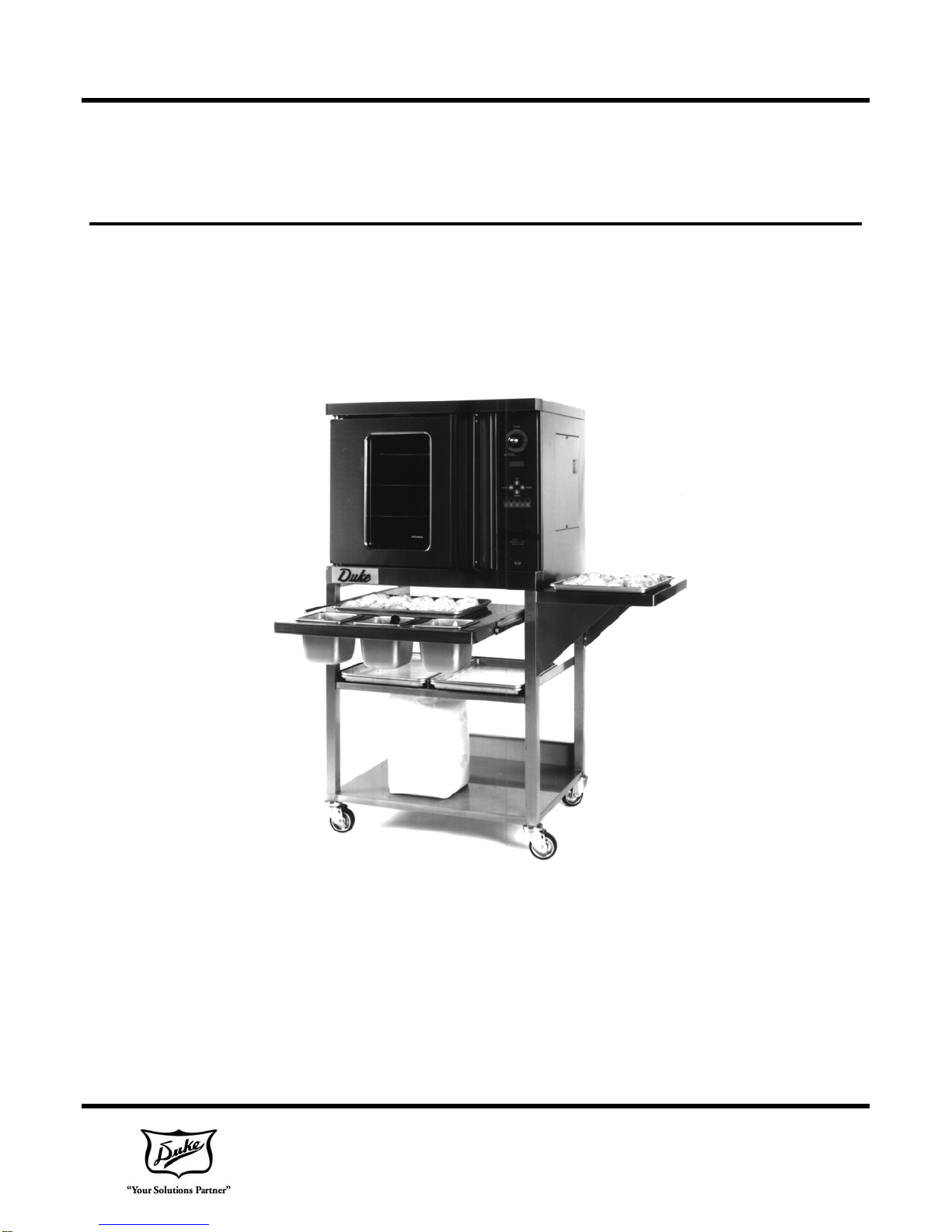
B. Delivery and Inspection
For transport, ovens are strapped down on wooden
skids and surrounded by "tri-wall" cartons to prevent
shipping damage. They have been carefully
inspected before they were packaged and
consigned to the carrier.
Upon Delivery of your Duke oven:
Look over the shipping container carefully
noting any exterior damage on the
delivery receipt.
Uncrate and check for any damage which
was not evident on the outside of the
shipping container. The carrier must be
notified within fifteen (15) days of the
delivery of the oven and the carton, skid
and all packaging materials must be
retained for inspection.
Duke Manufacturing Co. cannot assume liability for
loss or damage suffered in transit. The carrier
assumes full responsibility for the delivery in good
order when the shipment was accepted. If you need
assistance in preparing a freight claim call Duke
Manufacturing Co.
C. Location of the Oven
Proper planning and placement of the oven is
required for the proper function of the oven. Please
do consider the following requirements:
The oven should be placed in an area
which is free from drafts and accessible
for proper operation and servicing.
The area around the oven must be kept
clear of combustible materials. A minimum
of one (1) inch from the left or right side,
three (3) inches from the rear and eight (8)
inches from the floor must be maintained
between the oven and any combustible or
non-combustible surface.
D. Ventilation
It is important not to obstruct the cooling system flow
of the oven. Do not place any objects on top of the
oven. This oven should not be installed on a curb
base or sealed to the wall. Either condition can
prevent proper ventilation of the oven components.
The blower motor has a thermal protection device,
which will trip because of excessive ambient
temperatures at the side of the oven. If the device
trips continually, this condition should be corrected
immediately to avoid damaging the oven
permanently.
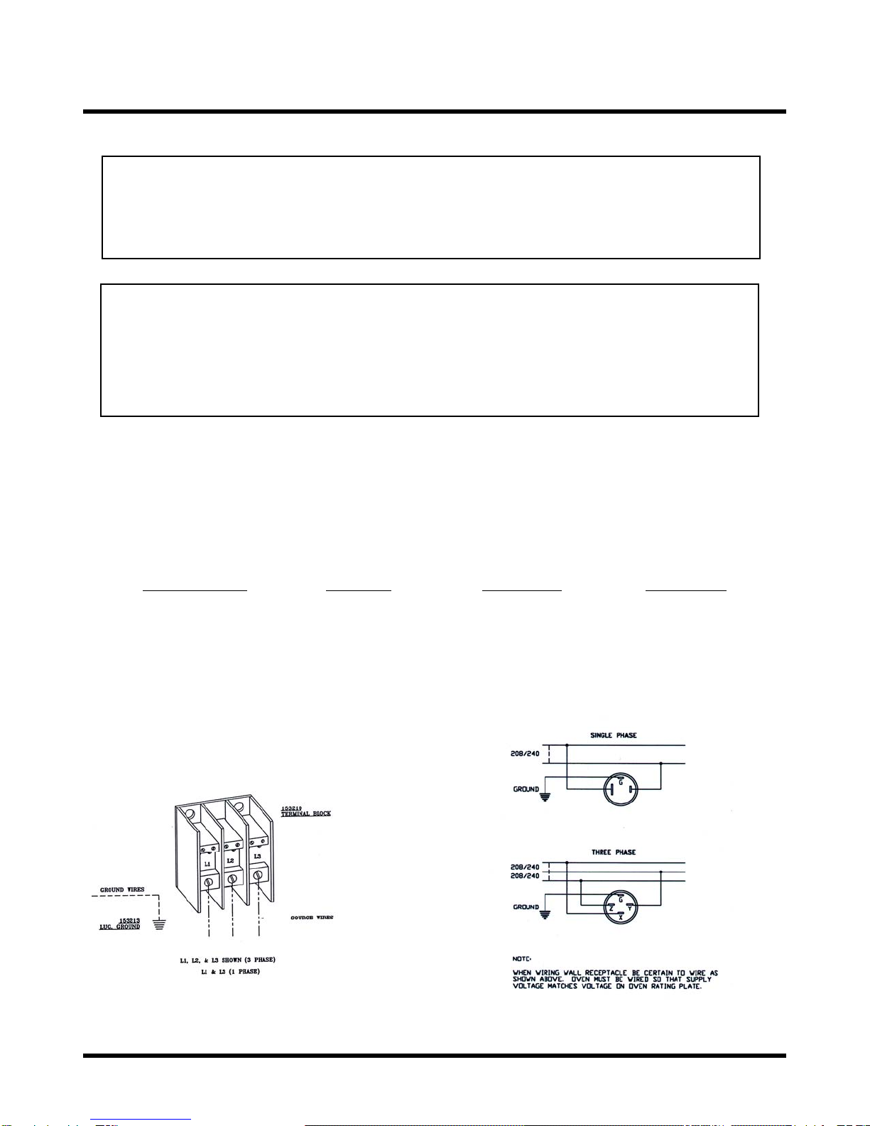
E. Electrical Connections
Verify the rating plate to be sure the oven
specifications concur with the voltage and phase to
be supplied to the oven. The rating plate and serial
number data are located behind the motor access
cover on the right side panel.
The following installation steps should only be
conducted by authorized service personnel or a
qualified electrician.
Your oven is supplied for connection to a 208 or 240
volt, 1-phase or 3-phase grounded circuit.
Before making any connections to these units, check
the rating plate to assure that the voltage and phase
rating of the oven is compatible with the electrical
supply. All ovens must be electrically grounded in
accordance with local codes. In the absence of local
codes, the National Electrical Code, ANSI/NFPA 70-
1990 (in Canada - CSA Std. C22.1) applies.