Duke AHPO User manual

DukeManufacturingCo.
2305 N. Broadway • St. Louis, MO 63102
800.735.3853 • 3.231.1130 • 314.231.5074 Fax
www.dukemfg.com
AHPO/EPO
PROOFEROVEN
OWNER’S MANUAL
IMPORTANT INFORMATION
READ BEFORE USE
PLEASE SAVE THESE INSTRUCTIONS
502821F

DukeManufacturingCo.
2305 N. Broadway • St. Louis, MO 63102
800.735.3853 • 3.231.1130 • 314.231.5074 Fax
www.dukemfg.com
2 of 29
CONTENTS
Manufacturing Introduction 2
Safety Instruction 3
Spec Sheets 4
Main Features 5
InstallationInstructions 6-9
Oven Start-Up 10
Proofer Operating Instructions 10-11
Oven Operating Instructions 12-13
Care and Cleaning 14
Troubleshooting 15-16
Door Adjustments and Gasket Maintenance 17-22
Air-wash door Information and Cleaning Instructions 23
Bulb Mounting Details 24
Parts List and Illustrations 25-27
Wiring Diagrams 28
CustomerAssistance 29
Manufacturers Introduction
TheDukeAHPOorEPOProoferOvenwere developed
in response to Customer’s need for uniform baking
capabilities to provide consistently high, “just baked”
breadquality.
TheDukeProoferOvenutilizesDuke’suniquedirectional
convection airflow technology that provides even heat
distribution and a uniform bake without the need for
turningpans during thebakecycle. Thisenhances the
quality and consistency of the baked products while
reducing food scrap/waste and simplifying operating
procedures.
Thelowprofileovenwon’tblocktheviewof menuboards
and will easily roll through a standard height door.The
oven and proofer doors are field reversible with a drip
channel on the proofer door to prevent water from
drippingonthefloor.
Fullwidthdoors on the ovenandprooferhelptodisplay
andmerchandise fresh baked breadtothecustomer.
Thecontrolsaresimple to operate, therearetwotimers
forindependenttimingoftheprooferandoven.
The full width oven and proofer cavity will accept
standard ½ size or full size sheet pans.
SupplierName: DukeManufacturingCo.
Address: 2305N.Broadway
St. Louis, MO 63102
Model#:
Serial #:
Date
Received:
Date
Installed:
Telephone: (800)735-DUKE(3853)
(314)231-1130
Fax: (314)231-5074
Service
Referral#:
Local
Service
Name:
Local
Service#:
AHPO-6/18-208
AHPO-6/18-230
AHPO-6/18-400
EPO-3/9-208
EPO-3/9-230
EPO-3/9-400
Note:“230V”canbeused
for220-240V
1Ph or 3Ph
3N(3Phw/neutral)
Note:“230V”canbeused
for220-240V
1Ph or 3Ph
3N(3Ph w/neutral)

DukeManufacturingCo.
2305 N. Broadway • St. Louis, MO 63102
800.735.3853 • 3.231.1130 • 314.231.5074 Fax
www.dukemfg.com
3 of 29
IMPORTANT SAFETY INSTRUCTIONS
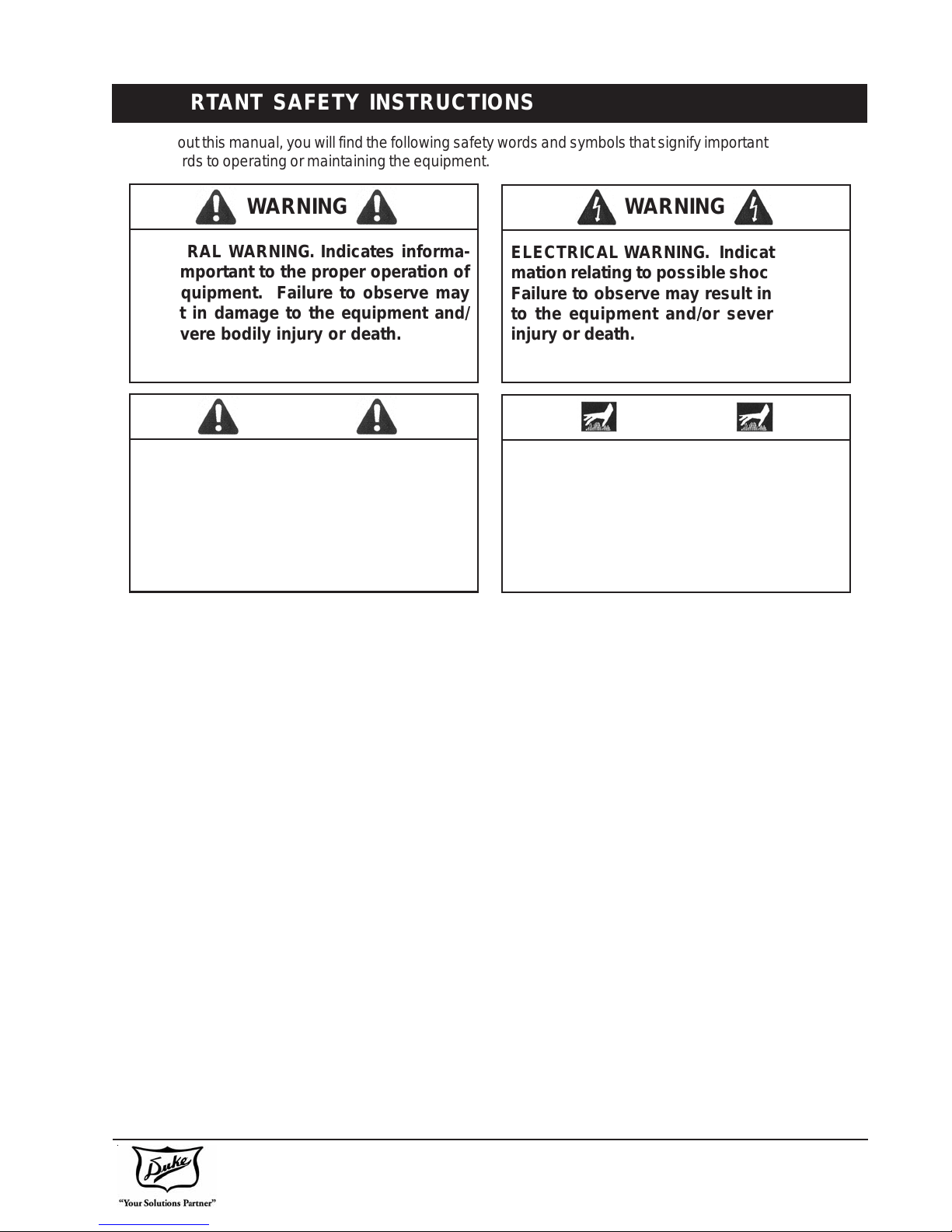
Throughoutthismanual,youwill find the following safetywordsandsymbolsthat signify important safety issues
withregardsto operating ormaintaining the equipment.
GENERAL WARNING. Indicates informa-
tion important to the proper operation of
the equipment. Failure to observe may
result in damage to the equipment and/
or severe bodily injury or death.
WARNING
ELECTRICAL WARNING. Indicates infor-
mation relating to possible shock hazard.
Failure to observe may result in damage
to the equipment and/or severe bodily
injury or death.
WARNING
GENERAL CAUTION. Indicates informa-
tion important to the proper operation of
the equipment. Failure to observe may
result in damage to the equipment.
CAUTION
HOT SURFACE WARNING. Indicates in-
formation important to the handling of
equipment and parts. Failure to observe
caution could result in personal injury.
WARNING
In addition to the warnings and cautions in this manual,
usethefollowingguidelines forsafeoperationoftheunit.
• Readallinstructions before usingequipment.
• For your safety, the equipment must be furnished
with a properly grounded cord connector. Do not
attempttodefeat the groundedconnector.
• Install or locate the equipment only for its intended
use as described in this manual.
• Do not use corrosive chemicals in this equipment.
• Do not operate this equipment if it has a damaged
cord or plug, if it is not working properly, or if it has
beendamagedordropped.
• Thisequipmentshould be servicedby qualified per-
sonnel only. Contact the nearest Duke authorized
servicefacility for adjustment orrepair.
• Do not block any openings on the unit.
• Aminimum clearance of6” (152,4 mm)from the top
of the unit to the ceiling must be provided.
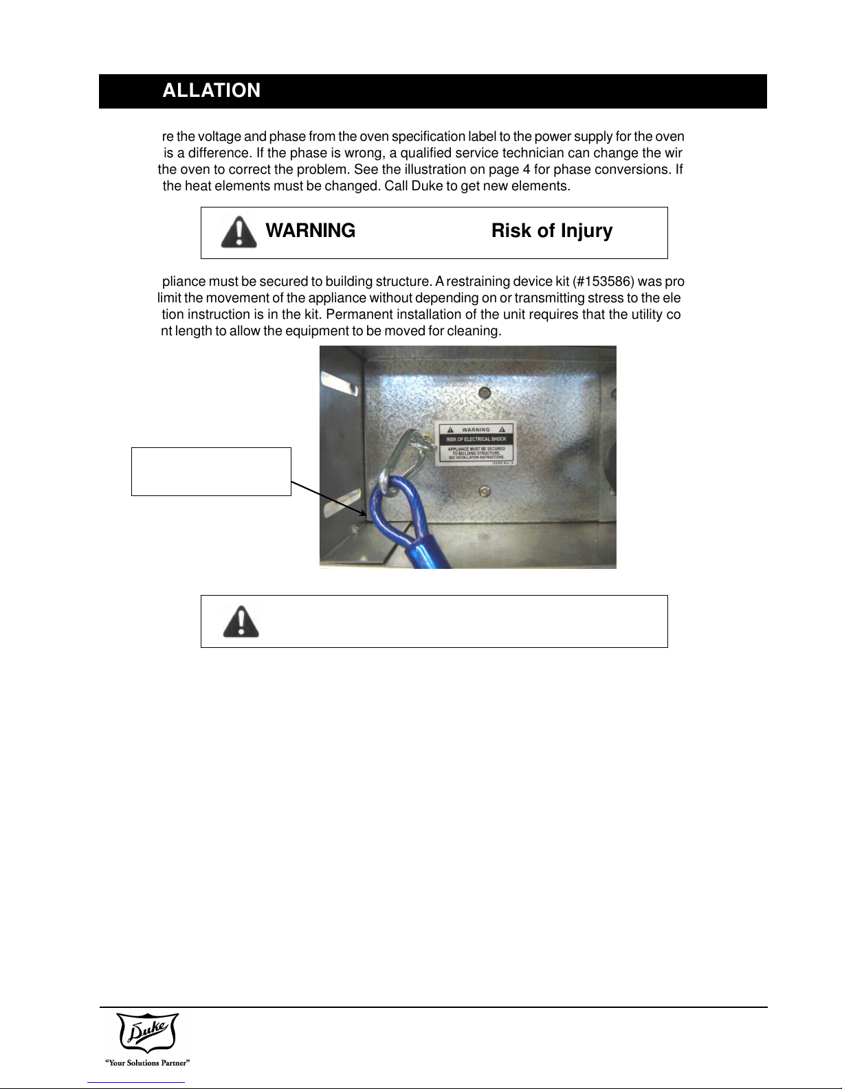
• Thisappliancemustbesecuredtobuildingstructure
(RestrainingDeviceKit).
• Keepcordaway from heatedsurfaces.
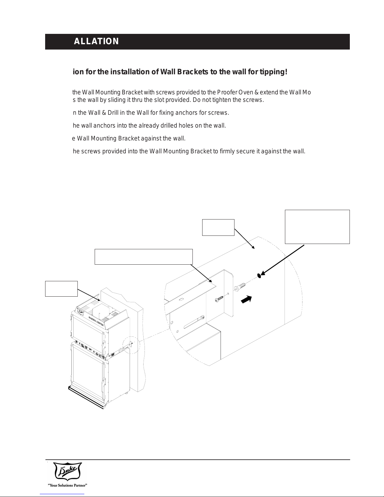
• To prevent tipping, securely attach unit to the wall
usingbracketsprovided.
Thefollowingwarningsandcautionsappearthroughout
thismanualand should be carefullyobserved.
• Turn the unit off, disconnect the power source and
allowunittocooldownbeforeperforminganyservice
ormaintenance onthe unit.
• The procedures in this manual may include the use
of chemical products. You must read the Material
SafetyData Sheets before using anyof these prod-
ucts.
• Theunitshouldbegroundedaccordingtolocalelec-
trical codes to prevent the possibility of electrical
shock. Itrequiresa grounded receptacle withsepa-
rate electrical lines, protected by fuses or circuit
breakeroftheproperrating.
• Allelectricalconnectionsmustbeinaccordancewith
local electrical codes and / or any other applicable
codes.
• Disposal of the unit must be in accordance with lo-
calenvironmentalcodesand/oranyotherapplicable
codes.
SAVE THESE INSTRUCTIONS

DukeManufacturingCo.
2305 N. Broadway • St. Louis, MO 63102
800.735.3853 • 3.231.1130 • 314.231.5074 Fax
www.dukemfg.com
4 of 29
SPEC SHEET
U.S. Patent. Other US and Foreign Patents Pending
Model AHPO or EPO
ShippingWeight:
CartonBox 625lbs/284Kg
ShippingWeight:
WoodenCrate 760lbs/345Kg
Volts Phase Hz Watts Amps
208 1 60 6650 32.0
208 1 50 6650 32.0
230(220-240) 1 60 6650 32.0
230(220-240) 1 50 6650 32.0
230(220-240) 3 60 6650 16.7
230(220-240) 3 50 6650 16.7
400(380-415) 3N 60 6650 16.7
400(380-415) 3N 50 6650 16.7
AHPO /
EPO

DukeManufacturingCo.
2305 N. Broadway • St. Louis, MO 63102
800.735.3853 • 3.231.1130 • 314.231.5074 Fax
www.dukemfg.com
5 of 29
MAIN FEATURES
LOWVOLTAGE
LIGHTINGSYSTEM
12VHALOGENLAMP
CONVECTIONOVEN
CONTROLPANEL
PROOFER
DRIPPAN

DukeManufacturingCo.
2305 N. Broadway • St. Louis, MO 63102
800.735.3853 • 3.231.1130 • 314.231.5074 Fax
www.dukemfg.com
6 of 29
INSTALLATION
Unpacking Unit
• Inspect the shipping carton and/or container, care-
fully noting any exterior damage on the delivery re-
ceipt, which was not evident on the outside of the
shippingcontainer(concealeddamage). Contactthe
carrierimmediatelyandfileadamageclaimwiththem.
Saveallpackingmaterialswhenfilingaclaim. Freight
damageclaimsaretheresponsibilityofthepurchaser
andarenot covered bythe warranty.
• FollowtheinstructionsontheCarton Box forunpack-
ing the unit.
• Inspect unit for damage such as, broken glass, etc.
• Reportanydentsorbreakageto source of purchase
immediately.
•Do not attempt to use unit if damaged.
• Removeallmaterials from unit interior.
• Ifunithas been stored inextremely cold area, waita
fewhoursbeforeconnectingpower.
Unit Placement
• Do not install unit next to source of heat, such as
deepfat fryer, etc.
• Installunitonlevelsurface floor.
• AMinimumClearanceof:
Unit Clearance
RightSide 0”
LeftSide 0”
Rear 0”
Ceiling 6”
Must be maintained between the unit and any
combustibleor non-combustible substance.
Properairflowaround unit cools electricalcomponents.
With restricted airflow, unit may not operate properly
and life of electrical parts is reduced.
To avoid risk of electrical shock or death,
this unit must be grounded or field con-
nection must not be altered.
WARNING
Earthing Instructions
Unit MUST be grounded.
Grounding reduces risk of
electricshockbyprovidingan
escape wire for the electric
current if an electrical short
occurs. When using an ap-
propriate plug it must be
plugged into an outlet that is properly installed and
grounded.
Consult a qualified electrician or servicer if grounding
instructions are not completely understood, or if doubt
existsas to whether the ovenis properly grounded.
Do not use an extension cord. This unit should be
plugged or field connected into a separate circuit with
theelectricalratingasprovided inproductspecifications.
All electrical connections must be in accordance with
localelectricalcodesand/oranyotherapplicablecodes.
External Equipotential
Earthing Terminal
Equipment has secondary earthing terminal.
Terminal provides external earthing connection
used in addition to earthing prong on plug. Located
on outside of oven back, terminal is marked with
thissymbol.

Duke Manufacturing Co.
2305 N. Broadway • St. Louis, MO 63102
800.735.3853 • 3.231.1130 • 314.231.5074 Fax
www.dukemfg.com
7 of 29
INSTALLATION
1. Compare the voltage and phase from the oven specification label to the power supply for the oven and call Duke
if there is a difference. If the phase is wrong, a qualified service technician can change the wire connections
inside the oven to correct the problem. See the illustration on page 4 for phase conversions. If the voltage is
wrong, the heat elements must be changed. Call Duke to get new elements.
WARNING Risk of Injury
2. This appliance must be secured to building structure. A restraining device kit (#153586) was provided with the
unit to limit the movement of the appliance without depending on or transmitting stress to the electrical conduit.
Installation instruction is in the kit. Permanent installation of the unit requires that the utility connection be of
sufficient length to allow the equipment to be moved for cleaning.
RESTRAINING DEVICE
KIT (PART # 153586)
WARNING Risk of Electric Shock
This Restraining Device MUST always be connected when the Appliance is in Service. Disconnect for movement,
servicing and or cleaning, then reconnect when the appliance has been returned to its normal position.
The appliance shall be installed using flexible conduit or equivalent to meet the local electrical codes and shall be
of sufficient length to allow the equipment to be moved for cleaning.
3. IMPORTANT: A minimum clearance of 6” from the top of unit to the ceiling must be provided.
4. TO PREVENT FROM TIPPING: Unit must be permanently attached to wall using wall-mounting brackets. Refer
page 9 for the instructions on Installation of Wall Brackets to the wall.
5. Check the swing of the door. The hinge side can be changed by following the instructions on the following pages.
The door swing direction can be changed in the field after you have a new drip channel for the proofer door. Call
Duke to get the new drip channel for the proofer door.
6. Check the door seal and make sure both doors close completely. If they do not close and seal properly, call
Duke for assistance.
7. Place the wire racks in the oven and proofer.

Duke Manufacturing Co.
2305 N. Broadway • St. Louis, MO 63102
800.735.3853 • 3.231.1130 • 314.231.5074 Fax
www.dukemfg.com
8 of 29
INSTALLATION
Illustration of the Wiring connection for single phase and three phase connections.

DukeManufacturingCo.
2305 N. Broadway • St. Louis, MO 63102
800.735.3853 • 3.231.1130 • 314.231.5074 Fax
www.dukemfg.com
9 of 29
INSTALLATION
Instruction for the installation of Wall Brackets to the wall for tipping!
1. MounttheWallMountingBracketwithscrewsprovidedtotheProoferOven&extendtheWallMountingBracket
towards the wall by sliding it thru the slot provided. Do not tighten the screws.
2. Mark on the Wall & Drill in the Wall for fixing anchors for screws.
3. Insert the wall anchors into the already drilled holes on the wall.
4. Butt the Wall Mounting Bracket against the wall.
5. Insert the screws provided into the Wall Mounting Bracket to firmly secure it against the wall.
6. Please re-ensure that the Bracket is firmly secured to the wall. Tighten the screws into the unit.
WALL
WALLMOUNTINGBRACKET
WALL
HOLEDRILLEDIN
WALLFORFIXING
BRKT

DukeManufacturingCo.
2305 N. Broadway • St. Louis, MO 63102
800.735.3853 • 3.231.1130 • 314.231.5074 Fax
www.dukemfg.com
10 of 29
OVEN START-UP
Have a qualified service technician or electrician connect the oven to the power supply. Check the door seal and
make sure both doors close completely. If they do not close and seal properly, call Duke for assistance
WATER LEVEL
INDICATOR
FIGURE - 1
• Fillthe proofer water panabout half fullof clean water.See FIGURE - 1.
• Turntheoven and prooferpower switches to theON position.
• Settheoventhermostatat 350°F(175°C),theprooferthermostatat105°F(40°C),andtheprooferhumidityat#3.
OVENCONTROLS
PROOFERCONTROLS
• All of the indicator lights should be on.
• Checktomakesurethat the oven and Prooferfansarerunning. Open the oven door.Theovenfanshould stop.
Close the door to continue.
• Set both timers to 20 minutes and check to make sure they time down and the buzzers work.
NOTE: When using timer for less than 10 minutes, you must turn the timer knob past 10 and then set time.
Ifthereareanyproblems,calltheservicedepartmentatDukeforassistancebeforeyoucallaserviceagency.Ifthe
problemis an operator or procedural error you will be liablefor the servicecharges.
Allowthe oven andproofer to pre-heatfor at least 30 minutes.
YourDuke Proofer Ovenisnow ready tooperate.
NOTE: Start-Up Form #502854 is available for you to fill out from our website www.dukemfg.com. Please
print and Fax to Duke at 314-231-2460.
PROOFER OPERATING INSTRUCTIONS

DukeManufacturingCo.
2305 N. Broadway • St. Louis, MO 63102
800.735.3853 • 3.231.1130 • 314.231.5074 Fax
www.dukemfg.com
11 of 29
PROOFER OPERATING INSTRUCTIONS
Makesurethehumiditypanhasfreshcleanwaterinit. Fill it with warmwatertogetthe best performance.Aregular
checkof the water levelis recommended duringoperation.Add water asrequired.
•Turn the proofer powerswitchon and set theprooferheat to thedesiredtemperature.Agoodstartingtempera-
ture is 105°F.
•Thelight above the heat thermostat will be on until the proofer has heatedto the set temperature.
•You may needto adjust thistemperature depending onyour results.Do not turnon the prooferhumidity at this
time.
•After the proofer has been heating for 20 minutes, turn the humidity switch to a setting of #3 or 4.
•You may need to adjust this setting depending on your results.
•When a light fog appears on the door glass the proofer is ready to load with dough.
•The humidity setting is too high if water is running down the door glass.
•If the door glass does not fog then the humidity setting is too low.
•Loadthe prooferwith breaddough andset thetimer for50 -60 minutes.
•You may need to adjust the time depending on the type of dough and your results.
•When it rises to 75 - 80 % of it’s final size, it is ready to bake.
•Sincetheproofercanholdmore pans of bread than theovencanbake,staggerthe loading in increments of the
ovenbaketime.This will prevent over proofingofthebread remaining in the prooferafterthefirst load is moved
totheoven.
•Ifthere is excessivehumidity on thedoor glass itis probably caused by a humidity setting thatis too highor by
havingthe humidity on whenthere is nodough loaded inthe proofer.
•Turntheprooferoffandremovethebottom panel.
•Removeexcess water that has accumulatedin the bottom of theproofer.
DO NOT…
•Run the proofer humidity without a load of dough.
ItisOKto leave the prooferheatonto maintainthetemperature,but turn the humidityoffiftheprooferisempty.
•Let the dough dry out while it is thawing.
Dough that is too dry will not fully rise in the proofer and may crack.
•Over-proof the dough
Excessive proofing will cause the bread to collapse after it has been baked. Make sure to adjust the proofing
timetopreventover-proofing.
•Under-proof the dough
If the bread is under-proofed it will not bake to the proper finished size and will have a dense cell structure.
•Proof frozen dough
Makesure the doughis thawed properlybefore loading it into theproofer.Thedoughshould be softandmoist
withthe center thawed.
DO…
•Watch the proofing process carefully and make adjustments if necessary.

DukeManufacturingCo.
2305 N. Broadway • St. Louis, MO 63102
800.735.3853 • 3.231.1130 • 314.231.5074 Fax
www.dukemfg.com
12 of 29
OVEN OPERATING INSTRUCTIONS
•Turnthe oven on and setthe temperature to 350° F
for bread and for Deli rolls. If this is done right after
theproofer is loadedwith the firstload, the ovenwill
be ready to bake when the first load is ready from
theproofer.
•Theovenpreheat time should befrom 20 to 30min-
utes.Theovendoorshouldbeclosed,exceptduring
loading and unloading. Load the oven quickly to re-
duce heat loss.
•Loadtheovenwith6pansofbread and set the bake
timer. The bake time can be adjusted to get the de-
siredcolor of thebaked bread.
•If the baking results are uneven or too dark, reduce
thetemperature and extend the bake time.
•If the bread is too dark, reduce the bake time. If the
bake time is reduced and the bread is still too dark
then reduce the temperature 15° F (10° C) and try
baking for a longer period of time. The same proce-
dure can be used to bake Deli rolls.
•If you are baking partial loads try to center the pans
inthe oven and startloading the ovenstarting at the
bottom shelf and working up to the top.
•Cookiesarebakedat325°F(163°C)andareloaded
in the oven the same way as bread and deli rolls.
•Keepinmindthatopeningtheovendoorallowsheat
to escape. If the door is left open too long it could
affect the performance of the oven. Under normal
conditionsofloadingthe oven this will notbeaprob-
lem.
OVENCONTROLS

DukeManufacturingCo.
2305 N. Broadway • St. Louis, MO 63102
800.735.3853 • 3.231.1130 • 314.231.5074 Fax
www.dukemfg.com
13 of 29
OVEN AND PROOFER TEMPERATURE CHECK
Ifthe oven orproofer temperature calibration seems tobe wrong, itcan be checked before aservice call is made.
Itis important tofollow the correct procedure toget an accuratereading. If the calibration isoff it is recommended
that you first call Duke Manufacturing Co. and talk to the service department before you schedule a service call.
Calling Duke first can save you time and money by eliminating other problems before a service call is made.
Themostimportantconcernwithtemperaturemeasurement is the accuracy of the thermometerandthelocationin
theoven cavity. Duke recommendsan electronic temperature meterwith a wirethermocouple.
1. Place the thermocouple at the geometric center of
the oven cavity. It can be fastened to the center of
themiddle wire shelf.
2. Start the oven and set the temperature control for
350° follow the oven to pre-heat for at least 45 min-
utes.
3. While watching the heat light on the control panel,
note the maximum and minimum temperatures
throughseveralcycles.
4. Theaveragetemperatureofseveral cyclesisthecali-
brationtemperature.Itisnormalforthistemperature
tohave a variance of +/-10° F.
5. The same steps can be used to check the proofer
temperature.Thetemperature control should beset
for 105° F and the normal variance is +/- 5° F
6. Loosen the small allen set screw on the side of the
knob.Adjustknobtothecalibrationtemperatureread-
ing and tighten setscrew. Use the same procedure
fortheproofer.
THERMOCOUPLEAT
GEOMETRICCENTER
OFOVENCAVITY

Duke Manufacturing Co.
2305 N. Broadway • St. Louis, MO 63102
800.735.3853 • 3.231.1130 • 314.231.5074 Fax
www.dukemfg.com
14 of 29
CARE AND CLEANING
WARNING
Bottom and sides of warmer wells are very hot and cool slowly.
CAUTION
Electrical shock hazard. Do not wash with water jet or hose.
Do not use caustic cleaners, acids, ammonia products, abrasive cleaners, or abrasive
cloths. These can damage the stainless steel and plastic surfaces.
DAILY
CLEANING INSTRUCTIONS
1. Wipe down the interior and exterior of the Proofer Oven with warm water and mild detergent
using a soft cloth.
2. Clean Proofer water pan using mild detergent and warm water. Ensure all soap is rinsed
from the Oven and Proofer surfaces and water pan to avoid flavor transfer to the bread.
3. Open the Proofer door and run the Proofer with the heat on for at least 30 minutes to dry it.
CAUTION
Do not use caustic cleaners, acids, ammonia products or abrasive cleaners or cloths.
These can damage the stainless steel and door gaskets.
MONTHLY
1. Check door handle screws for tightness.
2. Clean the Bottom Area of the Proofer. Turn the Proofer off, wait 30 minutes and/or when the
area is cool to touch, then remove the bottom fan cover panel. Wipe clean all the surfaces
for any particles that have accumulated around this area.
WARNING
QUARTERLY
1. Check the door gasket seal on the Oven and Proofer for leaks. See the section on
Door Adjustments and Gasket Maintenance for directions.

DukeManufacturingCo.
2305 N. Broadway • St. Louis, MO 63102
800.735.3853 • 3.231.1130 • 314.231.5074 Fax
www.dukemfg.com
15 of 29
TROUBLESHOOTING
Problem Yes No
1.Oven does not heat with oven
switch in the ON position and
Oven Temperature not set at
0°.
a.Areovenindicatorlightson?
b.DoesOvenFanwork?
c.Is Oven Door Securely
closed?
d.Is Supply Circuit Breaker
tripped?
e.Is Oven Breaker Switch
tripped?
f. Doesoven work?
2.Proofer does not heat with
Proofer Switch in the ON po-
sition Proofer
a.AreProoferindicatorlightson?
b.DoesProoferFanwork?
c.DoesOvenwork?
d.Is Supply Circuit Breaker
tripped?
e.Is Proofer Breaker Switch
tripped?
f. Doesoven work?
ObserveOvenFan.Goto “b”.
CallDukeService.
CallDukeService.
Reset Circuit Breaker. Try oven
again. Go to “f”.
ResetOvenBreakerSwitch.Goto
“f”.
Troubleshootingcomplete.
Reset Hi-limit Switch
CheckProoferOperation.Goto“d”.
Close Door securely. Go to “f”.
Check Fuses on Control Box. Go
to“f”.
CallDukeService.
CallDukeService.
ObserveProoferFan.Go to “b”.
CallDukeService.
CallServiceTechnician.
ResetCircuitBreaker.TryProofer
again.Go to “f”.
ResetProofer Breaker Switch.go
to“f”.
Troubleshootingcomplete.
CheckOven Operation. Go to “c”.
CheckOven Operation. go to “c”.
CheckSupplyCircuit Breaker. Go
to“d”.
CheckFusesonControlPanel.Go
to“e”.
CallDukesService.
CallDukesService.

DukeManufacturingCo.
2305 N. Broadway • St. Louis, MO 63102
800.735.3853 • 3.231.1130 • 314.231.5074 Fax
www.dukemfg.com
16 of 29
TROUBLESHOOTING
Problem Yes No
3.Oven/Proofer lights not work-
ing.
a.Is more than one light not
working?
b.Istransformerworking?
c.Dolightswork?
4.Proofer Humidity not work-
ing/insufficient with Humidity
Control not set to Off.
a.Doesprooferhumidityappear
tobeworking?
b.Doesprooferhumidityappear
tobeworking?
5.Proofer Humidity too high.
a.Is Proofer Humidity Control
setproperly?
b.Is proofer humidity working
properly?
Replaceinoperativelightbulbsand
recheck. Go to “b”.
Go to “c”.
Endoftroubleshooting.
Checktransformer. Goto “b”.
Replacetransformer. Goto “c”.
CallDukeService.
AdjustHumiditytonexthigherset-
ting. Wait 15 minutes. Go to “b”.
Adjusthumiditytoappropriateset-
ting.Endof troubleshooting.
Adjust humidity to maximum set-
ting. Wait 15 minutes. Go to “b”.
CallDukeService.
Removeprooferfloor and remove
accumulatedwater. Go to “b”.
Endoftroubleshooting.
Adjust humidity control to proper
level.Go to “b”.
CallDukeService.

DukeManufacturingCo.
2305 N. Broadway • St. Louis, MO 63102
800.735.3853 • 3.231.1130 • 314.231.5074 Fax
www.dukemfg.com
17 of 29
DOOR ADJUSTMENTS & GASKET MAINTENANCE
1. Remove cover from hinges to expose the screws that hold the hinge to the front of the oven. See FIG 1.
2. Removethehinge screws anddoor from theoven. See FIG 2.
3. Removethedoor handle screws and flipthe door handleover and replace it onthe door. See FIG 3.
4. Remove the six screws on the front of the oven to expose the hinge screw holes for the other swing direction.
See FIG 4.
5. Use the six screws to fill the unused hinge screw holes on the front of the oven.
6. Remove the latch strike plate from the front of the oven and move it to the other side. Use the screws from the
other side to fill the screw holes that are no longer used. See FIG 5.
7. Positionthedooronthefrontoftheovenandtighten the hinge screws. Make sure the door islevelwiththeoven
body before the screwsare tightenedpermanently. See FIG 6.
8. Adjust the door gasket seal.
Reversing Oven Door Swing Direction:

DukeManufacturingCo.
2305 N. Broadway • St. Louis, MO 63102
800.735.3853 • 3.231.1130 • 314.231.5074 Fax
www.dukemfg.com
18 of 29
DOOR ADJUSTMENTS & GASKET MAINTENANCE
Proofer Drip Channel Reversal:
The proofer door has a sloped drip channel on the bottom that directs any water that drips down the door into the
waterpanbelowthedoor.Whenthe door swing isreversedthis drip channel mustbe replaced with anewchannel
that has the slope in the proper direction. Contact Duke Manufacturing Service for a new drip channel before
changingdoorswingdirection.
LEFTHINGEDRIPCHANNEL
SLOPETOWARDSRIGHT
RIGHTHINGEDRIPCHANNEL
SLOPETOWARDSRIGHT

DukeManufacturingCo.
2305 N. Broadway • St. Louis, MO 63102
800.735.3853 • 3.231.1130 • 314.231.5074 Fax
www.dukemfg.com
19 of 29
DOOR ADJUSTMENTS & GASKET MAINTENANCE
Proofer Drip Channel Reversal:
1. Followthedirectionsforremovingthedoorfrom the previouspage.Whenthedoorisoffyoucanthenreplacethe
dripchannel.
2. Removethescrews that holdthe drip channelon and removethe drip channel.Use the samescrews to fill the
empty holes after the drip channel is off.
3. Locatethenewdrip channel onthe other endof the door. Make surethat the slopeis directed tothe hinge side
ofthe door. See FIGURE - 1.
4. Fastenthedrip channel tothe door with the self-tapping screws provided withthe new drip channel.
5. Followthedirections for mounting thedoor.
DIRECTION
OF SLOPE
NEWPOSITIONOF
THEDRIPCHANNEL
FIGURE - 1

DukeManufacturingCo.
2305 N. Broadway • St. Louis, MO 63102
800.735.3853 • 3.231.1130 • 314.231.5074 Fax
www.dukemfg.com
20 of 29
DOOR ADJUSTMENTS & GASKET MAINTENANCE
Door Gasket Leak Adjustments:
Thedoorsshould be checkedfor leaks every threemonths. The adjustmentcanbe made byfollowing the instruc-
tionsbelow. If the door gasket is damaged, or compressed permanently, it shouldbereplaced.CallDukeManufac-
turingCo. at 800-735-3853 toorder a newgasket before makingadjustments.
2. Adjustthedoor position by movingthe door framein or outto seal anygaps between thegasket and theoven.
Adjustment is made using the screws on the handle and the hinges.
IMPORTANT!!!
Be careful not to compress the gasket too much, or it will not allow the door to be closed.
Gasket is slightly
compressed
Gasket is not
touching
Gasket is not
touching
Gasket is
slightly
compressed
1. Withthedoorclosed,removethehingecoverswithascrewdriverandloosenthesixscrewsthatholdthehinges
tothe door.
This manual suits for next models
1
Table of contents
Other Duke Oven manuals