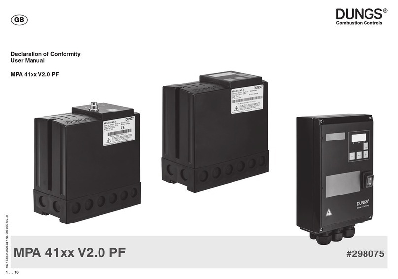
Dungs MPA 41 PF Series User manual

1 … 96
1 … 96
Printed in Germany • Edition 04.18 • Nr. 271 958
Manual
MPA 41xx PF
No. 271 958 - GB
Edition: 04.18 GB

3 … 96
2 … 96
Printed in Germany • Edition 04.18 • Nr. 271 958
EU-Konformitäts-
erklärung
Gebrauchs-
anleitung
EU-Declaration of
conformity
Instructions
Déclaration de
conformité EU
Notice
d’utilisation
Dichiarazione di
conformità EU
Istruzioni
di esercizio e
di montaggio
MPA 41xx PF
Feuerungs-
automat
Automatic Burner Système de com-
mande
automatique des
brûleurs
Sistema automa-
tico per bruciatori
MPA 41xx PF
# 257 539

3 … 96
2 … 96
Printed in Germany • Edition 04.18 • Nr. 271 958
HR SRB BIH SK
EU-Konformitäts-
erklärung
EU Declaration of
conformity
Déclaration de
conformité EU
Dichiarazione di
conformità EU
Produkt / Product
Produit / Prodotto MPA 41xx PF
Feuerungsautomat
Automatic Burner
Système de commande automatique des brûleurs
Sistema automatico per bruciatori
Hersteller / Manufacturer
Fabricant / Produttore Karl Dungs GmbH & Co. KG
Karl-Dungs-Platz 1
D-73660 Urbach, Germany
bescheinigt hiermit, dass die in die-
ser Übersicht genannten Produkte
einer EU-Baumusterprüfung un-
terzogen wurden und die wesentli-
chenSicherheitsanforderungender:
EU-Gasgeräteverordnung
2016/426
EU-Druckgeräterichtlinie
2014/68
in der gültigen Fassung erfüllen.
Bei einer von uns nicht freigegebe-
nen Änderung des Gerätes verliert
diese Erklärung ihre Gültigkeit.
certies herewith that the prod-
ucts named in this overview were
subjected to an EU Prototype
Test and meet the essential safety
requirements:
EU Gas Appliances Regulation
2016/426
EU Pressure Equipment Directive
2014/68
as amended.
In the event of an alteration of the
equipment not approved by us this
declaration loses its validity.
certifie par la présente que le
produit mentionné dans cette vue
d'ensemble a été soumis à un
examen de type de l'UE et qu'il
est conforme aux exigences en
matières de sécurité des dernières
versions en vigueur de :
l'ordonnance de l'UE relative
aux appareils au gaz
2016/426
à la directive UE « Équipements
sous pression »
2014/68
Ce communiqué n'est plus valable
si nous eectuons une modication
libre de l'appareil.
Con la presente si certica che i
prodotti citati in questa panoramica
sono stati sottoposti a una prova di
omologazione UE e che i requisiti
di sicurezza essenziali:
regolamento UE sugli apparecchi
a gas
2016/426
direttiva UE sulle attrezzatture
a pressione
2014/68
sonosoddisfattinellaversionevalida.
In caso di modica dell'apparecchio
nonammessa,questadichiarazione
perde di validità.
Prüfgrundlage der EU-Baumusterprüfung
Specied requirements of the EU Prototype Test
Base d'essai de l'examen de type de l'UE
Criteri di prova dell'omologazione UE
EN 298
EN 13611
EN 61508
Gültigkeitsdauer/Bescheinigung
Term of validity/attestation
Validité/certicat
Durata della validità/Attestazione
2021-05-22
CE0036
2028-04-08
CE-0123CT1090
Notizierte Stelle
Notied Body
Organisme notié
Organismo noticato
2014/68/EU
TÜV SÜD Industrie Service
GmbH
Westendstraße 199
D-80686 München
Germany
Notied Body number: 0036
(EU) 2016/426
TÜVSÜDProductService GmbH
Zertizierstellen
Ridlerstraße 65
D-80339 München
Germany
Notied Body number: 0123
Überwachung des QS-Systems
Monitoring of the QA system
Contrôle du système d'assurance qualité
Monitoraggio del sistema QS
Gewähltes Konformitätsverfahren
Modul B+D
Conformity process adopted: Mo-
dule B+D
Procédure de conformité sélection-
née : module B+D
Procedura di conformità seleziona-
ta: modulo B+D
Dr.-Ing. Karl-Günther Dalsaß,
Geschäftsführer / Chief Operating Ocer
Directeur / Amministratore
Urbach, 2018-04-21

5 … 96
4 … 96
Printed in Germany • Edition 04.18 • Nr. 271 958

5 … 96
4 … 96
Printed in Germany • Edition 04.18 • Nr. 271 958

7 … 96
6 … 96
Table of contents
Target group/warnings ........................................................................................................................................ 7-8
Data sheet .......................................................................................................................................................... 9-12
Approval overview .................................................................................................................................................13
System description/Variants/Accessories ..........................................................................................................14
General technical data ..........................................................................................................................................15
Connection diagram ..............................................................................................................................................16
Technical data outputs/inputs ........................................................................................................................ 17-19
Flame detection/Flame detector connection ......................................................................................................20
Installation/Dimensions MPA 412x ................................................................................................................. 21-23
Description of the functions
Unlocking function
Extended unlocking
Access level ...........................................................................................................................................................24
Description of the functions
Gas valves
Flame detector
Air pressure switch
HT signal, gas pressure switch or proof-of-closure contact
Parameterisation mode (manual operation)
Automatic/Parameterisation mode function switch ..........................................................................................25
Flow Chart ........................................................................................................................................................ 26-27
Description of the states ................................................................................................................................ 28-31
Parameters/Parameter change ............................................................................................................................32
Parameters/Parameter description ................................................................................................................ 33-41
Parameters/Factory setting ............................................................................................................................ 42-43
Status information ........................................................................................................................................... 44-45
MPA 41x2/Version with display ............................................................................................................................46
MPA 41x2/Overview of the display modes ..........................................................................................................47
MPA 41x2/On-screen display ...............................................................................................................................48
MPA 41x2/Operation display ................................................................................................................................49
MPA 41x2/Operation display additional information .........................................................................................50
MPA 41x2/Operation display parameterisation and service box .....................................................................51
MPA 41x2/Info display ...........................................................................................................................................52
MPA 41x2/Error display ........................................................................................................................................53
MPA 41x2/Error memory display .........................................................................................................................54
MPA 41x2/Parameterisation display .............................................................................................................. 55-61
MPA 41x2/Reset display ................................................................................................................................. 62-63
MPA 41xx errors without error ID ........................................................................................................................64
MPA 41xx errors from the basic system ....................................................................................................... 65-66
MPA 41xx errors from the extension system ......................................................................................................67
Errors from the application ..................................................................................................................................68
Annex ......................................................................................................................................................................69
Setting the bus address, bus termination .................................................................................................... 70-71
Probus ............................................................................................................................................................ 72-76
Modbus ............................................................................................................................................................. 77-84
Probus/Modbus Line lengths, baud rates, bus termination, pin assignment ...............................................85
Flame detector ................................................................................................................................................. 86-87
UV 41 (HE). ....................................................................................................................................................... 88-89
Ignition transformers ...................................................................................................................................... 90-92
VisionBox ...............................................................................................................................................................93
Printed in Germany • Edition 04.18 • Nr. 271 958

7 … 96
6 … 96
Printed in Germany • Edition 04.18 • Nr. 271 958
The target group of this manual is quali ed personnel of
the gas safety and regulating technology, skilled per-
sonnel or the persons instructed by them.
Due to their specialist training, knowledge and experience
and knowledge of standard regulations, they are capable
of evaluating the work assigned to them and recognising
possible dangers. Only they are permitted to carry out as-
sembly, commissioning, settings and maintenance on the
devices in compliance with the recognised rules for occupa-
tional safety.
Instruction manual
MPA 41xx PF
2. Warnings
Never carry out work as long as gas
pressure or voltage is applied. Avoid
open re. Please observe public regula-
tions.
The device must be protected from
vibrations and
mechanical impacts.
All adjustments and settings should
only be performed in accordance with
the instruction manuals of the connect-
ed machines.
The recognised occupational safety
rules and accident prevention regula-
tions must be observed and, if neces-
sary, personal protective measures
must be taken.
Connected line systems must be free
from dirt and contamination.
Hang this instruction manual in a readily visible place
inside the installation room! Do not carry out any
work until you have read the safety instructions of this
instruction manual.
The device may only be operated in
compliance with the operating condi-
tions stated on the type plate.
Prior to assembly, the device must be
inspected for transport damage.
The device must not be used in areas
with increased seismic risk.
Protection from environmental impacts
and weather conditions (corrosion, rain,
snow, icing, humidity (e.g. by conden-
sation), mould, UV radiation, harmful
insects, poisonous, corrosive solutions/
liquids (e.g. cutting and cooling uids),
must be guaranteed. Depending on the
installation site, it may be necessary to
take protective measures.
The device must not be exposed to
open re. Protection against lightning
strikes must be guaranteed.
2.1 General warnings
1. Target group
Explanation of the symbols
1, 2, 3,... = Order of
action
• = Instruction
GB

9 … 96
8 … 96
Printed in Germany • Edition 04.18 • Nr. 271 958
2.2 Designated use
The device is used in accordance with its designated use if
the following instructions are observed:
• Use only in compliance with the operating conditions
stated on the type plate.
• Use in perfect condition only.
2.3 Risks in case of misuse
• If used in accordance with their designated use, the
devices are safe to operate.
• Non-observance of the regulations may result in personal
injury or material damage, nancial damage or environ-
mental damage.
• Operator errors or misuse present risks to life and limb of
the operators and also to the device and other material
property.
• Malfunctions and faults must be eliminated immediately.
• Use only in observance of the instructions given in this
instruction manual and of national regulations.

9 … 96
8 … 96
µP Automatic burner
control system
MPA 41xx PF
Automatic burner control system for
high-speed burners with fast On/O
switching (pulse ring)
Description
Microprocessor-controlled automatic
burner control system for the intermittent
operation of high-speed burners with fast
On/O switching (pulse ring).
The program sequence and times can
be customised by setting software pa-
rameters.
Versions
• MPA 4112 PF with integrated display
• MPA 4122 PF
with metal housing
and integrated display
Application
For high-speed burners with fast On/O
switching (pulse ring). In particular for
industrial thermoprocessing equipment
to EN 746-2.
Approvals
EC type-examination certicate accord-
ing to the EC gas appliances directive:
MPA 41xx CE-0085BU 0487
EC type-examination certicate accord-
ing to the EC Pressure Equipment Direc-
tive:
MPA 41xx CE0036
Suitable for applications up to SIL 3.
Meets the requirement according to IEC
61508 (2nd Ed. 2011)
Certied by TÜV Süd
CSA certied product according to CSA
22.2 (MPA 4112 PF)
UL Recognized Component per UL 372,
UL 1998 (MPA 4112 PF).
Printed in Germany • Edition 04.18 • Nr. 271 958
• Automatic burner control system
for pulse ring applications
• Fast On/O switching
• High number of switching cycles
possible
• High temperature operation pos-
sible
• Congurable

11 … 96
10 … 96
The MPA 41xx PF is suitable for use with
high-speed burners with fast On/O
switching (pulse ring).
Flamemonitoringiscarriedoutbymeans
of an ionisation input.
• MPA 41xx PF can be congured via
display without laptop/PC
• High temperature operation can be
activated using an external switching
signal
• Extension module for Probus and
Modbus communication
• Air purge function (via bus)
ConnectiondiagramMPA4112PF
123456 7 89
10 11 12 13 14 15 16 17 18 19 20
P
N
G
P
6.3A T (10A F)
L1
N
PE
G
L1 NPE
G
L1
5A T
Ionisation
Not used
Supply
Ventilation
Safety chain
Operation
Fault
Ignition
transformer
High temperature NC
High temperature NO
Air pressure switch
Heat request
Reset
V1
V2
Not used
Flame detector
supply
* The connection cables used must be suitable for an ambient temperature of at least 75 °C (167 °F).
Connection diagram
MPA 4122 PF
1
LL 23456 7 89
10 11 12 13 14 15 16 17 18 19 20
L1
N
PE
G
q
P
N
G
q
P
L1 NPE
G
L1
5A T
6.3A T (10A F)
* The connection cables used must be suitable for an ambient temperature of at least 75 °C (167 °F).
Ionisation
Not used
Supply
Ventilation
Safety chain
Operation
Fault
Ignition
transformer
High temperature NC
High temperature NO
Air pressure switch
Heat request
Reset
V1
V2
Not used
Flame detector
supply
Printed in Germany • Edition 04.18 • Nr. 271 958

11 … 96
10 … 96
Display modes
Operation display
• Display of the current
operating state
• Display of the program state
• Display of bus address
Info display
• Display of ame quality
• Display of resettable counters for
start-up, operating hours and switch-
ing cycles
Error display
Display of the error memory
• Automatic activation of
error messages
• Additional information about faults
• Query of the ten last errors
Parameterisation display
• Password-protected functional lev-
els for service and OEM parameter
settings
• Setting important parameters such
as: Pre-venting time
Safety time for start-up
Post-venting time
Behaviour after ame
failure
Accessories
UV 41 (HE)
UV ame detector for high mechani-
cal load; metallic version. Suitable for
intermittent operation.
Communication
MPA 41xx extension module EM2/4
Additional circuit board and connector
set for Probus DP and Modbus com-
munication.
Parameter setting and service
MPA 41xx parameterisation and
service box
Universal support for device checking in
the eld; for producing small and medium
series.
MPA Vision Box
As addition to MPA41xx parameterisa-
tion and service box for setting param-
eters via a PC/laptop.
The program sequence and times can
be modied on the mounted display to
match each application.
A laptop or PC is not required for the
modication.
The automatic systems are protected by
passwords against unauthorised access.
All settings for the MPA 41xx PF auto-
matic burner control system can also be
made by means of a laptop/PC via MPA
Vision Box.
Printed in Germany • Edition 04.18 • Nr. 271 958
13 … 96
12 … 96
Subject to technical modication in the interest of technical progress.
µP-Automatic burner control system
MPA 41xx PF
Automatic burner control system for
one-stage and modulating gas burn-
ers
Technical data
Rated voltage 115 VAC -15 % ... +10 %
(depending on the model) 230 VAC -15 % ... +10 %
Frequency 50 Hz...60 Hz
Power consumption max. 10 VA
Fuse max. 6.3 A slow-blow or 10 A fast-blow
Operating signal max. 1 A
Interfering signal max. 1 A
Gas valves max. 2 A
Fan max. 1 A
Ignition max. 1 A
Flame detector supply 230 VAC / 10 mA
Flame detector lonisation
lonisation current/operation 10 - 20 µA
Shutdown sensitivity 1.2 µA
Short circuit current limiting approx. 280 µA
Unlocking due to fault Pushbuttons and remote unlocking
Protection type
MPA 4112 / IP 54
MPA 4122 / IP 65
Ambient temperature -40 °C - +70 °C
-20 °C - +60 °C (UL approval)
Ordering data
MPA 4112 PF/230 VAC Article no. 270 520
MPA 4112 PF/115 VAC Article no. 270 528
MPA 4122 PF/230 VAC Article no. 273 323
MPA 4122 PF/115 VAC Article no. 273 324
Extension module on request
EM2/4 MPA 41x
Probus DP,
Modbus
Flame detector
UV 41 Article no. 256 692
UV 41 HE Article no. 260 575
Company address
Karl Dungs GmbH & Co. KG
Siemensstraße 6-10
D-73660 Urbach, Germany
Phone +49 (0)7181-804-0
Fax +49 (0)7181-804-166
Postal address
Karl Dungs GmbH & Co. KG
Postfach 12 29
D-73602 Schorndorf, Germany
e-mail info@dungs.com
Internet: www.dungs.com
152.5
77
151.5
Dimensions [mm]
MPA 4112 PF
MPA 4122 PF
240 80
160
Printed in Germany • Edition 04.18 • Nr. 271 958

13 … 96
12 … 96
MPA41xx PF UV41 (HE) Components SIL SFF PFH
XIonisation input 399.48 % 1,80E-09
XInput HT 399.39 % 1,80E-09
X X UV41 + ionisation input 296.91 % 1,50E-07
Printed in Germany • Edition 04.18 • Nr. 271 958
Overview of approvals Article
number
CE FM UL
recog-
nized
UL
listed
CSA
C22.2
EAC AGA
MPA 4112 PF / AC 230 V 270520 x x x x
MPA 4112 PF / AC 115 V 270528 x x x x x
MPA 4122 PF / AC 230 V 273323 x
MPA 4122 PF / AC 115 V 273324 x
Extension module
EM2/4 MPA 411x 257960 xxx xx(x)*
EM2/4 MPA 412x 257961 x
Flame detector
UV41 256692 xxx xxx
UV41 HE 260575 xxx xx(x)*
Ignition transformers
DEZ 1xx all x(x)* x
DEZ 2xx all x(x)* x
Overview of approvals
Safety Integrity Level (SIL)
* on request

15 … 96
14 … 96
Printed in Germany • Edition 04.18 • Nr. 271 958
1 MPA 41xx PF system description
The MPA 41xx PF is suitable for use with
high-speed burners with fast On/O
switching (pulse ring).
Flamemonitoringiscarriedoutbymeans
of an ionisation input. High temperature
operation can be activated using an
external switching signal.
The MPA 41xx parameterisation and
service box is available for the produc-
tion of small series and for checking
the system when service is required.
For operation in burner networks, a
Probus/Modbus communication over
the extension module EM2/4 is pos-
sible.
Designation Article no. Voltage Display
MPA 4112 PF 270520 230 VAC 3-digit
7-segment display
MPA 4112 PF 270528 115 VAC 3-digit
7-segment display
MPA 4122 PF 273323 230 VAC 3-digit
7-segment display
MPA 4122 PF 273324 115 VAC 3-digit
7-segment display
System variants
Accessories
Ignition transformers:
- DEZ xxx
- Mains connection line
- Ignition line
Flame detector:
- UV: UV 41, UV 41 HE
Extension module EM
- EM 2/4: Probus DP, Modbus

15 … 96
14 … 96
Printed in Germany • Edition 04.18 • Nr. 271 958
General MPA 41xx PF
Protection type
MPA 4112 PF IP 54 / NEMA 12
Schutzart Metallgehäuse
MPA 4122 PF IP 65 (Attention: use suitable cable screw connections only!)
Ambient temperature
MPA
41xx PF
-40 °C ... +70 °C
Storage and transport -40 °C ... +80 °C
Humidity DIN 60730-1, no dewing admissible
Altitude Suitable for use up to 2000 m above the base height level
Lifetime
Switching outputs
At least 2.5 million switching operations depending on the contact load
Mounting position as desired
Dimensions
MPA 4112 PF
in mm
MPA 4112 (L x H x D): approx. 152.5 x 151.5 x 77 mm
Dimensions
MPA 4122 PF
in mm
MPA 4122 (L x H x D): approx. 160 x 240 x 80 mm
(excluding cable screw connection)
Weight MPA 4112 PF 0,82 kg
Weight MPA 4122 PF 2,2 kg
Technical data
Electrical data
Rated voltage 230 VAC -15 % ... +10 % or
115 VAC -15 % ... +10 %, depending on the version
Frequency 50 Hz / 60 Hz
Fuse 6.3 A slow-blow or 10 A fast-blow, integrated, 5 A slow-blow in the fuse holder, replaceable
Isolation No galvanic isolation between mains and 24 VDC or 5 VDC
Electrical connection Correct (!) phase connection and protective earth conductor according to the wiring
diagram
The contact protection for the UV sensor must be guaranteed by mounting it in the oper-
ating equipment
Power consumption
(own consumption)
Maximum 10 W
Typically 115 V 230 V
Standby 2.7 W 3.6 W
Operation 3.4 W 6.1 W
With extension card EM2/4:
Standby 4.0 W ... 4.7 W
Operation 4.6 W ... 7.4 W
Short-circuit current ION
against N
280 µA

17 … 96
16 … 96
123456 7 89
10 11 12 13 14 15 16 17 18 19 20
P
N
G
P
6.3A T (10A F)
L1
N
PE
G
L1 NPE
G
L1
5A T
Ionisation
Not used
Supply
Ventilation
Safety chain
Operation
Fault
Ignition
transformer
High temperature NC
High temperature NO
Air pressure switch
Heat request
Reset
V1
V2
Not used
Flame detector
supply
* The connection cables used must be suitable for an ambient temperature of at least 75 °C (167 °F)
Connection diagram
MPA 4122 PF
1
LL 23456 7 89
10 11 12 13 14 15 16 17 18 19 20
L1
N
PE
G
q
P
N
G
q
P
L1 NPE
G
L1
5A T
6.3A T (10A F)
* The connection cables used must be suitable for an ambient temperature of at least 75 °C (167 °F).
Ionisation
Not used
Supply
Ventilation
Safety chain
Operation
Fault
Ignition
transformer
High temperature NC
High temperature NO
Air pressure switch
Heat request
Reset
V1
V2
Not used
Flame detector
supply
Printed in Germany • Edition 04.18 • Nr. 271 958
Connection diagram
MPA 4112 PF
Attention:
After having removed the hood, you
might get in contact with the elec-
trical connections in the terminal
socket.Risk of fatal electric shocks!
Therefore, you must interrupt the
power supply before removing the
hood.
Do not remove the jumper between
terminals 1 and 2, which was
mounted in the factory. It is required
for the intended use of the automat-
ic burner control system.

17 … 96
16 … 96
Printed in Germany • Edition 04.18 • Nr. 271 958
Outputs
Designation Connec-
tion X
Safety-
related
Type of output Line length Electrical data
V1
Safety valve
13 xRelay contact Max. 100 m For 250000 switching cycles:
115/230 VAC / 2 A cos ϕ = 1
For 2.5 million switching cycles:
115/230 VAC / 1 A cos ϕ = 1
Minimum load 0.5 W
V2 congurable 14 xRelay contact Max. 100 m For 250000 switching cycles:
115/230 VAC / 2 A cos ϕ = 1
For 2.5 million switching cycles:
115/230 VAC / 1 A cos ϕ = 1
Minimum load 0.5 W
Ignition 15 xRelay contact Max. 100 m For 250000 switching cycles:
115/230 VAC / 1 A cos ϕ = 0,4
corresp.
115/230 VAC / 2.5 A cos ϕ = 1
For 2.5 million switching cycles:
115/230 VAC / 1 A cos ϕ = 1
Minimum load 0.5 W
Ventilation 8 - Relay contact Max. 100 m For 250000 switching cycles:
115/230 VAC / 1 A cos ϕ = 0,4
corresp.
115/230 VAC / 2.5 A cos ϕ = 1
For 2.5 million switching cycles:
115/230 VAC / 1 A cos ϕ = 1
HT function or
AUX out
Multifunction out-
put congurable
11 -Relay contact Max. 100 m 115/230 VAC / 1 A
cos ϕ = 1
Fault
Alarm
12 -Relay contact Max. 100 m 115/230 VAC / 1 A
cos ϕ = 1
FLW power 7-For UV41 (HE) Max. 100 m 230 VAC / 10 mA *1
Technical data
*1: The ame detector is always supplied with 230 VAC, even the 115 VAC version, via the "Flame detector supply" connection 7.
The sum of the currents of all safety-related consumers must not exceed 5 A (observe the value of the fuse)
The sum of the currents of all consumers must not exceed 6.3 A (10 A).

19 … 96
18 … 96
Printed in Germany • Edition 04.18 • Nr. 271 958
*1 Safety-relevant in the ame operation, not safety-relevant in the HT mode (ame detection o).
*2 For special applications, ionisation cable lengths of up to 50m are possible upon request.
*3 The Remote unlock function is safety-relevant.
Inputs
Designation Connec-
tion X
Safety-
related
Type of output Line length Electrical data
L1 1Contact
N3Contact
PE/Earth 4Contact
Input safety chain
(from L1, se-
cured via fuse in
fuse holder)
10 xContact Max. 100 m 115/230 VAC / max. 5 A
Flame detector
Ionisation*1
5 x Ionisation for
one or two-probe
operation
Max. 10 m*2 Threshold value: approx. 1.2 μA
Temperature
signal NO
16 xSwitching contact Max. 100 m 115/230 VAC "normally open"
Temperature sig-
nal NC or Proof
of closure or gas
pressure switch
min.
17 xSwitching contact Max. 100 m 115/230 VAC "normally closed"
Heat request 19 Switching contact Max. 100m 115/230 VAC
Air pressure
switch
18 XSwitching contact Max. 100m 115/230 VAC
Remote unlock-
ing*3
20 Switching contact Max. 100m 115/230 VAC

19 … 96
18 … 96
Printed in Germany • Edition 04.18 • Nr. 271 958
General information
Designation Type of input Electrical data
L1 connection over exchangeable
backup fuse
6.3 A slow-blow or 10 A fast-blow
Safety chain connection via exchangeable
backup fuse in the fuse holder
5 A slow-blow
TWI interface TWI Connection only for VisionBox and param-
eter setting box
NOT galvanically isolated!
Switch for parameterisation mode Bistable switch Selector switch inside the MPA (may only
be switched after having removed MPA from
the base)
"Display" unit Inside the housing for inte-
grated display
3x7 segment + 4 keys
Spark generator connection
The MPA 41xx PF does not have a built-
in ignition transformer.
For suitable ignition transformers,
see accessory list.
Attention: A special spark generator
is required depending on the electrode
arrangement (e.g. operation with one
electrode)
Technical data

21 … 96
20 … 96
Printed in Germany • Edition 04.18 • Nr. 271 958
One-electrode operation ionisation
*When using a DUNGS DEZ 1xx SEO ignition transformer for single-electrode operation,
the green/yellow cable must be connected to terminal 5.
Two-electrode operation ionisation
Flame detector UV41 (HE)
Flame monitoring and ignition
Flame detector connection
Flame
MPA connection
15: Ignition
3: N
4: PE
5: ION
7: FLW power
Flame
MPA connection
15: Ignition
3: N
4: PE
5: ION
7: FLW power
Flame
UV41 (HE)
MPA connection
15: Ignition
3: N
4: PE
5: ION*
7: FLW power
This manual suits for next models
2
Table of contents
Other Dungs Control System manuals
Popular Control System manuals by other brands

Siemens
Siemens LMV 5 Series user manual

Skydroid
Skydroid S1 Pro user manual

Lippert Components
Lippert Components OneControl HVAC Control 2.0 owner's manual

Entity
Entity STARGATE Series user manual

Mitsubishi Electric
Mitsubishi Electric PAR-CT01MAA-SB Instruction book

Graco
Graco Horizon Fluid Management Systems instructions

Nice
Nice MORX installation instructions

kozy heat
kozy heat SIT Proflame II System Overview & Troubleshooting Guide

LK Systems
LK Systems Wired Room Control NC Assembly instructions

CYBELEC
CYBELEC CybTouch 12 user manual

oventrop
oventrop Regumat F-130 Installation and operating instructions

REAC
REAC RCB11 user manual