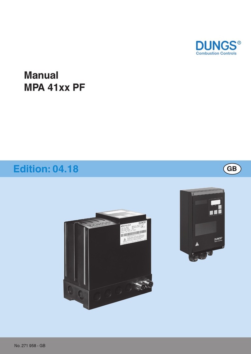
Dungs MPA 41 V2.0 PF Series User manual

MC • Edition 2023.04 • No. 298 075 Rev. -0
1 … 16 1 … 16
Declaration of Conformity
User Manual
MPA 41xx V2.0 PF
MPA 41xx V2.0 PF #298075
J

MC • Edition 2023.04 • No. 298 075 Rev. -0
2 … 16 3 … 16
Table of contents
1. Declaration of Conformity Page 3
2. Intentionally free Page 4
3. Target group Page 5
4. Warnings
4.1 General warnings Page 5
4.2
Intended use
Page
6
4.3 Risks in case of misuse Page 6
5. MPA 41xx V2.0 PF
5.1 Approvals Page 6
5.2 Versions Page 6
6. Technical data
Page
7
7. Electrical data
Page
7
8. Inputs / Outputs
Page
7
9. Assembly and eletrical installation
Page
8
10. Special functions
Page
9
11. Versions
Page
10
12. Settings
Page
10
13. Program sequence
Page
10
14. Connection diagram Page 10
15. Flame sensor: ionisation electrode Page 11
16. Approved ame detectors Page 11
17. Display options Page 12
18. Overview of the display modes MPA 4112 V2.0 PF, MPA 4122 V2.0 PF AM 41 Page 13
18.1 Operating mode display Page 13
18.2 Operating information: info display Page 14
19. Start up Page 14
20. Behavior in the case of faults Page 14
21. Error overview - minimal display (MPA 4114 V2.0 PF) Page 15
22. Error overview - display (MPA 41x2 V2.0 PF and display AM 41) Page 15
23. Replacement of MPA 41xx V1.1 V2.0 PF with MPA 41xx V2.0 V2.0 PF Page 15

MC • Edition 2023.04 • No. 298 075 Rev. -0
2 … 16 3 … 16
Product MPA 41xx V2.0 PF Automatic Burner Control System
Manufacturer Karl Dungs GmbH & Co. KG ▪Karl-Dungs-Platz 1 ▪73660 Urbach / Germany
hereby certies that the products listed in this overview have been subjected to an EU type-examination (production type) and meet the essential safety requirements of:
• EU Gas Appliances Regulation (EU) 2016/426
• EU Pressure Equipment Directive 2014/68/EU
• EMC Directive 2014/30/EU
• Low-Voltage Directive 2014/35/EU
in the valid version.
All of the components certied according to the Pressure Equipment Directive are equipment parts with safety function.
Any unauthorised modication to the device will render this declaration invalid.
The object of the declaration described above conforms with the relevant Union harmonisation legislation.
This Declaration of Conformity is issued under the sole responsibility of the manufacturer.
Specied requirements of the EU type-examination (production type)
EN 298
EN 13611
EN 50156-2
EN 61508-Part 1 to 3
Term of validity / attestation 2033-03-05
CE0036
2033-03-08
CE-0123DL1090
Notied body
2014/68/EU
TÜV SÜD Industrie Service GmbH
Westendstraße 199
D-80686 Munich
Germany
Notied Body number: 0036
(EU) 2016/426
TÜV SÜD Product Service GmbH Zertizierstellen
Ridlerstraße 65
D-80339 Munich
Germany
Notied Body number: 0123
Monitoring of the QA system Conformity process adopted: Module B+D
B. Sc. MBA Simon P. Dungs,
Managing Director
Urbach, 2023-03-21
1. EU declaration of conformity
J

MC • Edition 2023.04 • No. 298 075 Rev. -0
4 … 16 5 … 16
Intentionally free

MC • Edition 2023.04 • No. 298 075 Rev. -0
4 … 16 5 … 16
The target group of this manual is spe-
cialised gas safety and control technol-
ogy personnel, qualied persons or the
persons instructed by them. They are
capable of assessing the work assigned
to them as well as potential hazards on the
basis of their technical training, knowledge
and experience, as well as knowledge of
the relevant regulations. Only they are per-
mitted to install, start up, adjust and service
the equipment under compliance with the
accepted rules of industrial safety.
Place this user manual in an easily
viewable location in the installation
room. Perform work only after reading
the safety instructions in this user man-
ual.
3. Target group 4. Warnings
Never perform work when gas
pressure or voltage is pres-
ent. Avoid open re. Comply
with government regulations.
Carry out all settings and set-
ting values only in accordance
with the user manual of the
connected machine.
The device may be operated
only in accordance with the
operating conditions speci-
ed on the rating plate.
The device must be examined
for transport damage prior to
installation.
The device must not be ex-
posed to an open ame. Pro-
tection against lightning must
be provided.
4.1 General warnings
The accepted rules of industri-
al safety and the accident pre-
vention regulations must be
followed, if necessary taking
safety measures to ensure the
protection of persons.
The device must be protected
against vibrations and me-
chanical impacts.
The device must be secured
in areas with heightened risk
of earthquakes in accordance
with local regulations.
Protection must be ensured
against environmental and
climatic inuences (corro-
sion, snow, icing,
moisture
(e.g. due to condensation),
mould, UV radiation, harmful
insects and toxic, corrosive
solutions / liquids (e.g. cut-
ting / cooling uids)). Subject
to the installation site, safe-
ty measures must be taken
when necessary.
Liability for safety-relevant
systems, devices or compo-
nents.
No liability on the part of
DUNGS applies in the cases
of safety-related components,
equipment and systems. Both
the product liability for conse-
quential damages of any kind
and the liability for material
defects if these safety-relat-
ed components, equipment
and systems are overridden,
modied or repaired by un-
authorised technical sta or
when using replacement parts
not specically permitted for
the application.
Radiation heat is a source
of heat that can result in an
ambient temperature above
the permitted temperature.
Provide proper shielding to
protect against radiant heat.
Attached accessories must
be suitable and approved for
the medium.
After work has been complet-
ed, carry out a function test.
Safety
first
O.K.

MC • Edition 2023.04 • No. 298 075 Rev. -0
6 … 16 7 … 16
4.2 Intended use
The device is considered to be used as
intended if the following instructions are
followed:
• Use in heating systems and industrial
thermal process systems.
• Use only in accordance with the oper-
ating conditions specied on the rating
plate.
• Use only with the ame monitoring
equipment specied in the approval.
• Use only in good order and condition.
• Malfunctions must be rectied immedi-
ately by authorised specialist sta and
resolved prior to any further use.
• Use only when following the instruc-
tions in this user manual and the
national regulations.
4.3 Risks in case of misuse
• The equipment is reliable in operation
when used normally.
• Personal or consequential material
damage, nancial damage or environ-
mental damage is possible in the event
of non-observance of the instructions.
• Misuse or misapplication pose a risk
to the life and limb of the operator, the
device and other material assets.
5. MPA 41xx V2.0 PF
Microprocessor-controlled automatic burn-
er control system for continuous operation
of gas burners when using monitoring with
ionisation ame monitors or for intermittent
operation when using UV ame monitoring.
5.1 Approvals
EC type-examination certicate according to:
• EC Gas Appliances Regulation
• EC Pressure Equipment Directive
Suitable for applications up to SIL 3.
Meets the requirements of IEC 61508
5.2 Versions
The conformity / user manual relates to the following
MPA 41xx V2.0 PF versions:
Version Operating voltage Material number
MPA 4112 V2.0 PF 115 VAC 297424
MPA 4112 V2.0 PF 230 VAC 297421
MPA 4114 V2.0 PF 115 VAC 297430
MPA 4114 V2.0 PF 230 VAC 297427
MPA 4122 V2.0 PF 115 VAC 297436
MPA 4122 V2.0 PF 230 VAC 297433
AM 41 V2.0 (Display) internal 297004
These MPA41xx versions are already parameterised
and can be used immediately.
Changes to program procedures and functions may be
made by qualied users.
A password is required to change the parameter set-
tings.
All settings can be found in the MPA 41xx V2.0 PF
product manual:
www.dungs.com / .....

MC • Edition 2023.04 • No. 298 075 Rev. -0
6 … 16 7 … 16
6. Technical data
Protection class
MPA 4112 V2.0 PF, MPA 4114 V2.0 PF
IP 54
External display IP 54 front / IP 20 rear
Protection class MPA 4122 V2.0 PF IP 65
Ambient temperature -40 °C...+70 °C
Storage and transport -40 °C...+80 °C
Humidity DIN 60730-1, no dewing admissible
Operating altitude Suitable for use up to 2 000 metres above
mean sea level
Service life of switching outputs At least 250 000 switching operations
2.5 million cycles at max. 1 A/output
Installation position Any
Dimensions MPA 411x V2.0 PF in mm MPA 4112 / 4114 (L x H x D): approx.
152.5 x 165 x 77 mm
Weight MPA 411x V2.0 PF 0.82 kg
Dimensions MPA 411x V2.0 PF in mm
MPA 4122 (L x H x D): approx. 160 x 240 x
100 mm
Weight MPA 411x V2.0 PF 2.2 kg
7. Electrical data
Rated voltage 230 VAC -15% ... +10% or 115 VAC -15%
... +10%
Frequency 50 Hz ... 60 Hz
Fuse 6.3 A delayed or 10 A fast-acting,
integrated, replaceable
Isolation No galvanic isolation between grid and
24 VDC or 5 VDC
Electrical connection In-phase connection and protective earth
connection according to connection
diagram
The touch protection for the UV sensor
must be ensured through installation in
the operating equipment
Power consumption (own consumption) Maximum 10 W
Short-circuit current ION against N 115 / 230 VAC 280 µA
Outputs
Designation
Safety-
relevant
Output type Line
length
Electrical data
V1 / V2
Gas valves •Relay contact 100 m
115 / 230 VAC / 2 A cos φ = 1 / minimum load
0.5 W
Ignition •Electr. relay 100 m 115 / 230 VAC / 2 A cos φ = 1*
Fan Relay contact 100 m 115 / 230 VAC / 1 A cos φ = 0.4 corresponds
to 115 / 230VAC / 2.5 A cos φ = 1
Operation / fault Relay contact 100 m 115 / 230 VAC / 1 A cos φ = 1
Supply
Flame detector
100 m 230 VAC / 10 mA (also version MPA 115 VAC)
*1 With a pre-ignition time > 100 s or a duty cycle (DC) > 80 % of the ignition output, the maximum permissible
output current is reduced to 1.5 A.
The total currents of all safety-related consumers must not exceed 5 A (note the safety value)
The total currents of all consumers must not exceed 6.3 A (10 A).
Inputs
Designation Input type Line length Electrical data
Safety chain Potential-free contact 100 m 115 / 230 VAC / max. 5 A
Flame detector 1 (ionisation) Ionisation 10 m Threshold: approx. 1.2 μA
X 16 to X 20
e.g. remote unlocking, air pressure
monitor, heat request, ame detector 2
Switching contact 100 m 115 / 230 VAC
AM 41 display connetion - 10 m internal
Use ame detector 2 for line lengths > 10 m.
For special applications, ionisation line lengths of up to 50 m are possible on request.
Dierent functions can be parameterised for inputs X 16 to X 20.
The safety devices must be wired between the pre-wired fuse and Pin 10
Safety devices in the safety chain must have potential-free normally open or normally closed contacts suitable
for mains voltage and at least 10 A current load.
The connection lines must be suitable for an ambient temperature of at least 75 °C.
8. Inputs / outputs

MC • Edition 2023.04 • No. 298 075 Rev. -0
8 … 16 9 … 16
The installation regulations applicable at the installation site must be observed.
• The data specied on the rating plate must be observed to ensure safe operation
• Before opening the housing, switch o the power to the system and secure it against being switched back
on.
• Observe the maximum switching power of the outputs.
• Version MPA 4122 V2.0 PF: Voltage is also present in the housing when the power switch is
switched o.
• The switch in the MPA4122 housing is not an disconnector within the meaning of DIN EN 60730. That is,
even if the switch is deactivated, mains voltage is still present within the housing – risk of fatal electric
shocks! As a result, the power supply must be interrupted before opening the housing.
• Version MPA 4114V2.0 PF: The connection to the AM 41 display may be established or disconnected only
in a voltage-free state.
For inductive loads, pay attention to the inrush current!
The cross-section of the connection lines must be observed.
The connection lines used must be suitable for an ambient temperature of at least 75 °C (167 °F).
A suitable high-voltage line must be provided for ignition and ionisation lines. Only use interference-suppressed
connector plugs for the ignition electrode (1 kOhm)
All components must be provided with a protective earth at the connection points intended for this purpose.
Only use suitable cable ttings – observe IP protection.
The MPA is supplied with continuous voltage; the heat requirement is not used for the power supply.
All protective conductor connections must be professionally executed; the MPA can be destroyed if they are not,
especially in single electrode operation.
In addition to the protective conductor connections on the MPA, also check the protective conductor connection
of the burner.
Ionisation ame monitoring is possible only in earthed networks.
An isolating transformer is required for non-earthed networks.
Max. cross-section of line: 2.5 mm² / PE 6 mm²
EMC-compliant version
The ignition line must be laid separately to the other current-carrying lines.
Do not route in metallic pipes or bundled with other lines.
Create all earth connections professionally and ensure low transition resistance.
Use interference-suppressed ignition plugs or suitable high-voltage lines with corresponding line resistance.
Installation of MPA 4122 V2.0 PF
4x screw M4, length min. 20 mm
The housing is not earthed using the mounting screws.
The protective earth must be provided via the connection (screw M4 x 6).
9. Assembly and electrical installation

MC • Edition 2023.04 • No. 298 075 Rev. -0
8 … 16 9 … 16
Installation of MPA 4112 V2.0 PF and MPA 4114 V2.0 PF
Installation on DIN rail or
Installation with 2x screw M4, length min. 20 mm
Drill mounting holes with 4.5 mm drill
Place a sealing washer or O-ring underneath to obtain the protection class IP 54.
10. Special functions
Unlock function
Pressing the unlock button allows the MPA to be unlocked when in a locked state.
Actuation time > 0.5 s < 5 s. The device can be unlocked a maximum of ve times in 15 minutes.
Further unlocking is possible only after a waiting period of three minutes.
Enhanced unlock (only using the unlock button in the device)
Resetting the unlock block:
Hold the unlock button > 5 s < 10 s until the display starts ashing, then release the unlock key and press
again.
The “Enhanced unlock” function is active in all operating states of the MPA.
Pressing it during operation results in a safety shutdown and subsequent restart.
Parameterisation switch
Attention: For a factory-set MPA, the switch must be set to the “Auto” position.
For additional information, refer to the product manual
MPA 4112 V2.0 PF and
MPA 4114 V2.0 PF
MPA 4122 V2.0 PF
Installation of display AM 41
For installation, create a 68 x 68 mm cut-out at the installation location.
The maximum permissible material thickness of the installation surface is 5 mm.
Use connection line AM 41 # 298790, (max. 10 m) to connect the display.
PIN12345678
Colour White Brown Green Yellow Grey Pink Blue Red
AM 41 plug assignment
Pin 1

MC • Edition 2023.04 • No. 298 075 Rev. -0
10 … 16 11 … 16
Version Voltage Display Housing design IP
MPA 4112 V2.0 PF 115 Integrated Luranyl 54
MPA 4112 V2.0 PF 230 Integrated Luranyl 54
MPA 4114 V2.0 PF 115 External Luranyl 54
MPA 4114 V2.0 PF 230 External Luranyl 54
MPA 4122 V2.0 PF 115 Integrated Aluminium 65
MPA 4122 V2.0 PF 230 Integrated Aluminium 65
Settings Seconds (s)
Pre-purge time 0
Ignition time 1
Safety time 3
Safety time operation 1 1
Post-purge time 0
Terminal
Failure
Watchdog phase
Check air sw off
Wait for heat request
Check improper flame
Air on, wait for air sw
Safety time, TFI
Flame sense
Stabilize
Operate
Flame disappearance
Restart delay
State Number 0 5 6 7 8 9 12 13 14 19 22 23
State Display Info Fxx 01 A4 A0 A1 A1 A1 A1 A2 A3 A4 A4
Safety Chain 10
Heat Request 19
Flame 1 5
Air Sw In 18
Remote Reset 20
V1 Out 13
Operation 11
Ignition Out 15
Air Out 8
Alarm Out 12
Output on Input on
Input ignored
P
11. Versions
12. Settings
13. Program sequence
14. Connection diagram
MPA 4112 V2.0 PF and MPA 4114 V2.0 PF
MPA 4122 V2.0 PF
5A T
12345678910 11 12 13 14 15 16 17 18 19 20
q
P
N
6.3A T (10A F)
L1
N
PE
NPE
1LL2
345678910 11 12 13 14 15 16 17 18 19 20
N
6.3A T (10A F)
NPE
L1
N
PE
q
P
5A T

MC • Edition 2023.04 • No. 298 075 Rev. -0
10 … 16 11 … 16
*When using a DUNGS DEZ 1xx SEO ignition transformer for single electrode operation,
the green / yellow line must be connected to terminal 5.
Two electrode operation, ionisation
Single electrode operation, ionisation
MPA connector
15: Ignition
3: N
4: PE
5: ION
7: FLW power
16: FLW2 NO
Flame
15. Flame sensor: ionisation electrode
MPA connector
15: Ignition
3: N
4: PE
5: ION*
7: FLW power
16: FLW2 NO
Flame
Manufac-
turer
Designation Type
Output
signal
Safety
time
Flame
detector
Total reacti-
on time after
ame lift-o
Inter-
mit-
tent
Continuous
operation
–Ionisation
electrode
Ionisation Ionisation 0 s P41 Yes No
DUNGS UV41 (HE)
UV tube Ionisation 0,125 s
(= 2/16 s)
P41 + 0,125 s
Yes
No
DUNGS UV42
UV tube Switching
output
230 VAC
0,125 s
(= 2/16 s)
P44 + 0,125 s
Yes
No
DUNGS FLW 41I
Ionisation Switching
output
230 VAC
0,19 s
(= 3/16 s)
P44 + 0,19 s
Yes
No
BST
Solutions
FLW 20
(KLC 1000)
UV tube Ionisation 0,5 s P41 + 0,5 s Yes No
KLC 10/230
KLC 1000/230
FLW 20 UV
KLC 10/230 RA
KLC 1000/230
RA
FLW 10 IR V2.1
BST
Solutions
KLC 2002
FLW 10 IR
Flicker
detection
with
frequency
monitoring
Ionisation 0,5 s P41 + 0,5 s Yes NoKLC 2002
FLW 10 IR V2.1
KLC 20/230
When using ame detectors, the reation times must be observed and adjusted by correctly setting the
corresponding parameters.
16. Approved ame detectors

MC • Edition 2023.04 • No. 298 075 Rev. -0
12 … 16 13 … 16
The MPA 4114 V2.0 PF version features a minimal display of two LEDs that display the device status.
LED yellow
• Display of operating state
LED red
• Display of a fault
• Flashing signal for error code
• Display pause status during parameterisation
RESET button
• Unlocking
• Enhanced unlock
• Conrmation of change of access level
Information – LED yellow
LED o: fault present
LED permanently on
Waiting for heat request until second safety time ame detection
Flashing LED (0,5 Hz): operating indicator
LED ashing rapidly (2 Hz):
Waiting for gas pressure in the case of gas shortage and safety chain open.
Information – LED red
Fault
The most important error codes are displayed using dierent ashing patterns
The remaining error codes are displayed using a permanently on LED.
Information – both LEDs: password input expected. Both LEDs ash alternately (refer also to the product manual)
LED yellow LED red
17. Display options
MPA 4114 V2.0 PF
minimal display
MPA 41xx V2.0 PF display
Valid for internal and external display AM xx
Display 3 x 7 segment
LED:
Blue: heat request
Yellow: ame quality (ashes in the case of a
bad ame)
Red: fault
Release button
RESET function and conrmation of input
Back
Plus
Increase the indicated value
Minus
Reduce the indicated value
Note the appearance on a 7-segment
display
1. Digits
6 =
8 =
0 =
2. Letters
B or b =
D or d =
O or o =

MC • Edition 2023.04 • No. 298 075 Rev. -0
12 … 16 13 … 16
Mode
Operating mode display
Error display
Information display
Error memory display
Resetting display
Flashing display
Active
in normal operating conditions, if there is no fault.
if the unit is subject to a malfunction interlock.
From the operating- or error display by pressing the key combination
and
From the operating- or error display by pressing the key combination
and
From the operating- or error display by pressing the key combination
and
Depending on display mode:
1. Prompt to conrm the switch of access level
2. To intentionally reboot the MPA, press and hold the unlock button for
more than 5 seconds (“Enhanced unlock”)
3. Processor 2 error, see error list
4. New password after password change
5. Unit restart, all segments and LEDs ash
18. Overview of the display modes MPA 4112, MPA 4122 AM 41 18.1 Operating mode display
The display can show dierent information
depending on the operating status of the
automatic burner control system:
Waiting for heat request
Warten auf Sicherheitskette
bei oener Sicherheitskette
Warten auf Gasdruck
bei Gasmangel
Ruhestandskontrolle LDW
Warten auf
Wärmeanforderung
Fremdlichtkontrolle Sicher-
heitszeit
Flammenerkennung
Stabilisierzeit
Betrieb
Wiedereinschaltverzögerung

MC • Edition 2023.04 • No. 298 075 Rev. -0
14 … 16 15 … 16
20. Behaviour in the case of faults
If an error occurs, the MPA displays the detected error using coded information.
Attention: The cause of the detected error must be established.
If no impairment of function can be determined on connected equipment parts, the automatic burner control
system must be replaced.
19. Startup
The system must be in inspected by qualied personnel prior to initial startup or after modications have been made.
- Power supply
- Gas supply
- Gas leak-tightness
The MPA is supplied with continuous voltage; the program starts when mains voltage is provided to the heat
request input.
When “3” is shown in the display, the unit in operating mode.
Errors are displayed with F xx
The info display can be called up from the operating mode by pressing the + and Enter buttons.
The information display can be used to access information about the ame quality, the resettable operating
hours counter, the resettable start-up counter and the switching cycle counter.
This mode is exited again after 60 seconds if no further keys are pressed during this time.
18.2 Operating information: info display
Display of
ame quality in μA
Display of
resettable runtime
meter
Tens of thousands
digit
Display of
resettable runtime
meter
Hundreads digit
Display of
resettable runtime
meter
digit
Display of resettable
start counter
Tens of thousands
digit
from each info display state
Back to operation display
Display of
resettable start
counter
Hundreads digit
Display of
resettable start
counter
digit
Display of
switching cycle
counter V2
Tens of thousands
digit
Display of
switching cycle
counter V2
Hundreads digit
Display of switching
cycle
counter V2
digit
Back to operation display
Inside temperature
MPA in °C
At minus-
temperatures
A is substituted by
„-“
Software Version-
Index
Processor 1
Software Version-
Index
Processor 2
Software Version-
Index
Processor EM/x
Status FLW2 NO

MC • Edition 2023.04 • No. 298 075 Rev. -0
14 … 16 15 … 16
Flashing code Error code Error description
1 x ash F A2 Safety chain interrupted
2 x F 60 Parameter change not enabled
3 x F A7 No ame during rst safety period
3 x F bC No ame during second safety period
3 x F A9 Flame failure during stabilisation time
4 x F A8 Flame failure during operation
5 x F AA Idle state control for air pressure monitor
5 x F AB No air pressure
6 x F A6 Extraneous light detected
7 x F 18 Error due to expansion module
8 x F 16 Undervoltage or TWI communication
Error code Error description
F 03 ERROR_WD_HARDWARE
Ambient temperature too high, overvoltage
F 04 ERROR_UNLOCKING_DENIED
Unlocks in the last 15 minutes; wait or use enhanced unlock
F 11 ERROR_UNDERVOLTAGE
Lower voltage limit reached; check power supply
F 12 ERROR_POWERFAILURE
Voltage interrupted during startup, operation or shutdown
F 1d ERROR_PROCESSORFAILURE
MPA is subject to strong EMC interference
F A2 ERROR_SAFETY_CHAIN_OPEN
Safety chain opened; check limiters, breakers and wiring
F A4 ERROR_FEEDBACK_V1_INCORRECT
Faulty output, external voltage present at output; check wiring, EMC eect on valve line
F A5 ERROR_FEEDBACK_V2_INCORRECT
Faulty output, external voltage present at output; check wiring, EMC eect on valve line
F A6 ERROR_EXTERNAL_LIGHT
Ground fault on ionisation electrode, fuel is owing out and burning (check valves), UV tube
defective
F A7 ERROR_NO FLAME_DURING_FIRST SAFETY TIME
Ionisation electrode in incorrect position, ignition electrode in incorrect position, no
fuel present, electrical grid connection for MPA is switched, re monitor defective, line
interrupted.
F A8 ERROR_FLAME_GONE_OUT_DURING_OPERATION
Burner, ame detector, ionisation electrode defective. Check wiring and mixture setting.
F A9 ERROR_FLAME_GONE_OUT_DURING_STABILISATION
See F A7 and F A8
F AA ERROR_IDLE STATE CONTROL_LDW
Air pressure monitor defective, air pressure signal during idle state control, incorrect setting
of air pressure monitor.
F Ab ERROR_NO_AIR_PRESSURE
Air pressure monitor defective, air pressure signal during idle state control, incorrect setting
of air pressure monitor.
F AC ERROR_FEEDBACK_IGNITION_INCORRECT
Faulty output, external voltage present at output, check wiring, EMC eect on ignition
transformer line
F Ad ERROR_LACKOFGAS_GDWMIN
No fuel, gas pressure monitor defective, incorrect adjustment or wiring of gas pressure
monitor
F b3 ERROR_GASVALVEFEEDBACK_FALSE
See F AC
F b6 ERROR_LIMIT SWITCH_V1 (POC)
F bA ERROR_FALSEFLAME_START
Extraneous light > 1 min after heat request
F bC ERROR_NO FLAME_DURING_SECOND SAFETY TIME
F bD ERROR_FLAME DETECTOR_NOT SWITCHED_INVERSE
F bF ERROR_SAFETY_CHAIN_NOT_POTENTIAL-FREE
For a detailed description, see the MPA 41xx V2.0 PF product manual
The V2.0 automatic burner control systems are backward compatible.
Prior to replacement, check that the program sequence and parameter values are set correctly.
For further information, see the MPA 41xx product manual.
21. Error overview – minimal display (MPA 4114 V2.0 PF)
22. Error overview display (MPA 41x2 V2.0 PF and display AM 41)
23. Replacement of MPA 41xx V1.1 with MPA 41xx V2.0 PF

MC • Edition 2023.04 • No. 298 075 Rev. -0
16 … 16 16 … 16
J
Safety-relevant components Design-related service life Standard
Permanent storage temperature
Cycle number Years
Valve proving systems 250 000 10 EN 1643
0…45 °C
32…113 °F
Gas pressure sensing device 50 000 10 EN 1854
Air pressure sensing device o 250 000 10 EN 1854
Gas failure switch N / A 10 EN 1854
Automatic burner control system 250 000 10 EN 298
EN 230
UV ame sensor 1N / A 10 000 h³---
Gas pressure regulators 1N / A 15 EN 88-1
EN 88-2
Gas valve with valve proving system 2after error detected EN 1643
Gas valve without valve proving system 2DN ≤ 25 200 000
25 < DN ≤ 80 100 000
80 < DN ≤ 150 50 000
10 EN 161
Gas / air ratio control systems
N / A 10 EN 88-1
EN 12067-2
1 Decreasing performance on account of ageing
2 Gas families II, III
3 Operating hours
N / A not applicable
Storage periods
Lagerzeiten ≤ 1 Jahr verkürzen nicht die konstruktionsbedingte Lebensdauer / Storage time ≤ 1 year does not reduce the designed lifetime /
DUNGS recommends a maximum storage period of 3 years
The Pressure Equipment Directive (PED) and the Directive on the energy performance
of buildings (EPBD) require a regular inspection of heat generators to guarantee a high
degree of long-term eciency and thus minimal environmental impact.
There is a need to replace safety-related components after they reach the end of
their useful life:
Karl Dungs GmbH & Co. KG
Karl-Dungs-Platz 1
D-73660 Urbach, Germany
Telephone +49 7181-804-0
Fax +49 7181-804-166
info@dungs.com
www.dungs.com
This manual suits for next models
3
Table of contents
Other Dungs Control System manuals
Popular Control System manuals by other brands

Coelbo
Coelbo SWITCHMATIC 1 Advanced Settings

BlueCarve
BlueCarve Spark Plasma Setup

Carel
Carel FLSTDMAHUE user manual

TeeJet Technologies
TeeJet Technologies Dynajet FLEX 7140 INSTALLATION, SETUP AND USER GUIDE

Intesis Software
Intesis Software IntesisHome Configuration guide

Russound
Russound A-BUS brochure