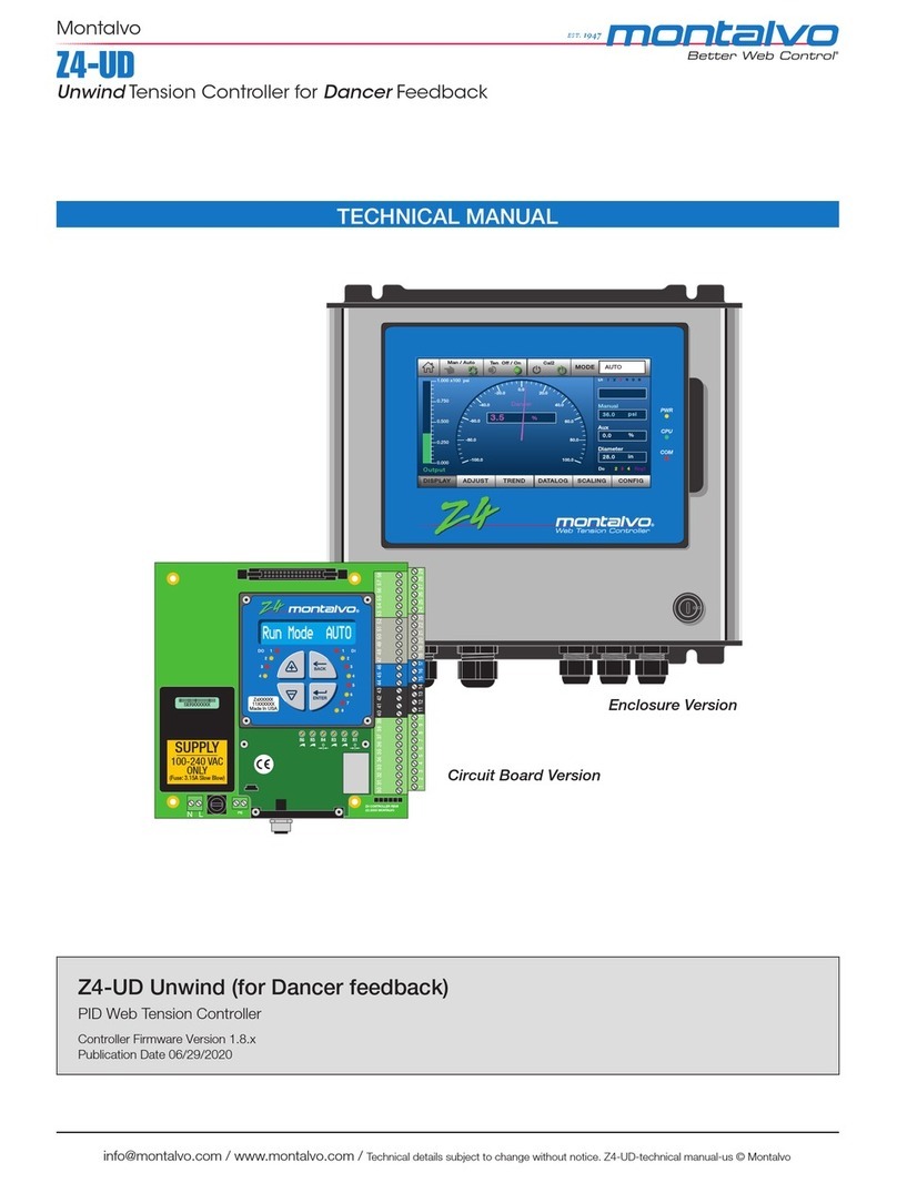
AuCom EMX4i User manual

EMX4i Soft Starter
USER MANUAL

CONTENTS
710-14888-00C EMX4i User Manual 1
Contents
1. About This Manual.....................................3
1.1 Disclaimer ......................................................3
2. Caution Statements ..................................4
2.1 Electrical shock risk......................................4
2.2 Unexpected Operation ..................................5
2.3 Avertissements à l'attention des clients
canadiens........................................................6
3. System Design ...........................................8
3.1 Feature List ....................................................8
3.2 Model Code.....................................................9
3.3 Model Selection .............................................9
3.4 Current Ratings .......................................... 10
3.5 Dimensions and Weights .......................... 13
3.6 Physical Installation................................... 14
3.7 Accessories ................................................. 14
3.8 Main Contactor ........................................... 15
3.9 Circuit Breaker ........................................... 15
3.10 Power Factor Correction........................... 16
3.11 Short Circuit Protection Devices (SCPD) 16
3.12 IEC Coordination with Short Circuit
Protection Devices ..................................... 17
3.13 UL Coordination with Short Circuit
Protection Devices ..................................... 18
3.14 Fuse Selection for Type 2 Coordination .. 21
3.15 Specifications.............................................. 22
3.16 Disposal Instructions................................. 23
4. Installation ...............................................24
4.1 Command Source ...................................... 24
4.2 Setup Procedure Overview ....................... 24
4.3 Inputs............................................................ 25
4.4 Outputs......................................................... 27
4.5 Control Voltage ........................................... 28
4.6 Power Terminations .................................. 28
4.7 Typical Installation ..................................... 31
4.8 Quick Setup ................................................. 33
5. Setup Tools ..............................................34
5.1 Set Date and Time...................................... 34
5.2 Command Source ...................................... 34
5.3 Commissioning........................................... 34
5.4 Run simulation............................................ 35
5.5 Load/Save Settings .................................... 36
5.6 USB Save & Load........................................ 36
5.7 Auto-Start/Stop........................................... 38
5.8 Network Address........................................ 38
5.9 Digital I/O State ........................................... 39
5.10 Analog I/O State .......................................... 39
5.11 Serial Number & Rating............................ 39
5.12 Software Versions....................................... 40
5.13 Thermistor Reset........................................ 40
5.14 Reset Thermal Model.................................40
6. Logs.......................................................... 41
6.1 Event Log ..................................................... 41
6.2 Counters....................................................... 41
6.3 QR Code........................................................ 41
7. Keypad and Feedback ............................. 42
7.1 The Keypad .................................................. 42
7.2 Remote Keypad........................................... 43
7.3 Lighten/Darken the Display ...................... 43
7.4 Starter status LEDs.................................... 44
7.5 Displays........................................................ 44
8. Operation ................................................. 46
8.1 Start, Stop and Reset Commands............ 46
8.2 Command Override.................................... 46
8.3 Auto-Start/Stop........................................... 46
8.4 PowerThrough ............................................ 47
8.5 Emergency Mode........................................ 48
8.6 Auxiliary Trip................................................ 48
8.7 Typical Control Methods............................ 49
8.8 Soft Start Methods...................................... 50
8.9 Stop Methods .............................................. 53
8.10 Pump Clean................................................. 57
8.11 Reverse Direction Operation..................... 57
8.12 Jog Operation.............................................. 58
8.13 Inside Delta Operation ............................... 59
8.14 Secondary Motor Set.................................. 60
9. Programmable Parameters .................. 61
9.1 Main Menu ................................................... 61
9.2 Altering Parameter Values ....................... 61
9.3 Adjustment Lock......................................... 61
9.4 Parameter List............................................ 62
9.5 1 Motor Details............................................ 70
9.6 2 Motor Start/Stop...................................... 71

CONTENTS
2EMX4i User Manual 710-14888-00C
9.7 3 Motor Start/Stop-2.................................. 74
9.8 4 Auto-Start/Stop ....................................... 77
9.9 5 Protection Levels..................................... 80
9.10 6 Protection Action..................................... 82
9.11 7 Inputs......................................................... 86
9.12 8 Relay Outputs........................................... 89
9.13 9 Analog Output .......................................... 91
9.14 10 Display..................................................... 92
9.15 11 Pump Clean............................................ 95
9.16 12 Communications Card ......................... 96
9.17 20 Advanced ................................................ 99
9.18 30 Pump Input Configuration ................. 100
9.19 31 Flow Protection ................................... 102
9.20 32 Pressure Protection ........................... 103
9.21 33 Pressure Control................................. 104
9.22 34 Depth Protection ................................. 105
9.23 35 Thermal Protection............................. 105
9.24 36 Pump Trip Action................................. 106
10. Application Examples............................108
10.1 Smart Card - Pump Control and
Protection .................................................. 108
10.2 Smart Card - Level Controlled Pump
Activation ................................................... 110
11. Troubleshooting ....................................112
11.1 Protection Responses.............................. 112
11.2 Trip Messages........................................... 112
11.3 General Faults .......................................... 121

ABOUT THIS MANUAL
710-14888-00C EMX4i User Manual 3
1. About This Manual
WARNING
Indicates a hazard that may cause personal injury or death.
CAUTION
Indicates a hazard that may damage the equipment or installation.
NOTE
Provides helpful information.
1.1 Disclaimer
The examples and diagrams in this manual are included solely for illustrative
purposes.
The information contained in this manual is subject to change at any time and
without prior notice. In no event will responsibility or liability be accepted for direct,
indirect or consequential damages resulting from the use or application of this
equipment.
© 2018 AuCom Electronics Ltd. All Rights Reserved.
As AuCom is continuously im
proving its products it reserves the right to modify or change the specification
of its products at any time without notice
. The
text, diagrams, images and any other literary or artistic works
appearing in this document are protected by copyright. Users may copy some of the material for their
personal reference but may not copy or use material for any other purpose without the prior consent of
AuCom Electronics Ltd. AuCom endeavours to ensure that the information contained in this document
including images is correct but does not accept any liability for error, omission or differences with the
finished product.

CAUTION STATEMENTS
4EMX4i User Manual 710-14888-00C
2. Caution Statements
Caution Statements cannot cover every potential cause of equipment damage but
can highlight common causes of damage. It is the installer's responsibility to read
and understand all instructions in this manual prior to installing, operating or
maintaining the equipment, to follow good electrical practice including applying
appropriate personal protective equipment and to seek advice before operating this
equipment in a manner other than as described in this manual.
NOTE
The EMX4i is not user serviceable. The unit should only be serviced by
authorised service personnel. Unauthorised tampering with the unit will
void the product warranty.
FOR YOUR SAFETY
•The STOP function of the soft starter does not isolate dangerous voltages
from the output of the starter. The soft starter must be disconnected by
an approved electrical isolation device before accessing electrical
connections.
•Soft starter protection features apply to motor protection only. It is the
user’s responsibility to ensure safety of personnel operating machinery.
•The soft starter is a component designed for integration within an
electrical system; it is therefore the responsibility of the system
designer/user to ensure the system is safe and designed to comply with
relevant local safety standards.
2.1 Electrical shock risk
WARNING – ELECTRICAL SHOCK RISK
The voltages present in the following locations can cause severe electric
shock and may be lethal:
•AC supply cables and connections
•Output cables and connections
•Many internal parts of the starter
SHORT CIRCUIT
The EMX4i is not short circuit proof. After severe overload or short circuit,
the operation of the EMX4i should be fully tested by an authorised service
agent.

CAUTION STATEMENTS
710-14888-00C EMX4i User Manual 5
GROUNDING AND BRANCH CIRCUIT PROTECTION
It is the responsibility of the user or person installing the EMX4i to provide
proper grounding and branch circuit protection according to local electrical
safety codes.
2.2 Unexpected Operation
WARNING – ACCIDENTAL STARTS
In some installations, accidental starts may pose an increased risk to safety
of personnel or damage to the machines being driven. In such cases, it is
recommended that the power supply to the soft starter is fitted with an
isolating switch and a circuit-breaking device (eg power contactor)
controllable through an external safety system (eg emergency stop, fault
detector).
WARNING – STARTER MAY START OR STOP UNEXPECTEDLY
The EMX4i will respond to control commands from various sources, and
could start or stop unexpectedly. Always disconnect the soft starter from
mains voltage before accessing the starter or load.
WARNING – DISCONNECT MAINS BEFORE ACCESSING STARTER OR
LOAD
The soft starter has built-in protections which can trip the starter in the
event of faults and thus stop the motor. Voltage fluctuations, power cuts and
motor jams may also cause the motor to trip.
The motor could restart after the causes of shutdown are rectified, which
may be dangerous for personnel. Always disconnect the soft starter from
mains voltage before accessing the starter or load.
CAUTION – MECHANICAL DAMAGE FROM UNEXPECTED RESTART
The motor could restart after the causes of shutdown are rectified, which
may be dangerous for certain machines or installations. In such cases, it is
essential that appropriate arrangements are made against restarting after
unscheduled stops of the motor.

CAUTION STATEMENTS
6EMX4i User Manual 710-14888-00C
2.3 Avertissements à l'attention des clients canadiens
AVERTISSEMENT
L'icône AVERTISSEMENT ci-contre signale les informations concernant des
risques pouvant entraîner des blessures graves, voire mortelles. Pour votre
sécurité, veuillez consulter les avertissements sur cette page ou demander
une copie du présent manuel en français auprès de votre distributeur local.
AVERTISSEMENT – RISQUE DE CHOC ÉLECTRIQUE
Les zones suivantes sont soumises à des tensions pouvant provoquer des
risques de chocs électriques graves, voire mortels :
•Raccordement et câbles d'alimentation AC
•Câbles et raccordements de sortie
•De nombreuses pièces internes du démarreur
PAR SÉCURITÉ
•La fonction STOP du démarreur progressif n'isole pas des tensions
dangereuses de la sortie du démarreur. Le démarreur progressif doit
être déconnecté par un dispositif d'isolement électrique approprié avant
d'accéder aux connexions électriques.
•Les fonctions de protection du démarreur progressif ne concernent que
la protection du moteur. Il relève de la responsabilité de l'utilisateur
d'assurer la sécurité des personnes travaillant sur les machines.
•Le démarreur progressif est un appareil conçu pour s'intégrer dans un
système électrique ; il relève donc de la responsabilité du concepteur ou
de l'utilisateur de veiller à ce que ce système soit sûr et conçu selon les
normes de sécurité locales en vigueur.
AVERTISSEMENT – DÉMARRAGES ACCIDENTELS
Dans certaines installations, des démarrages accidentels peuvent
provoquer un risque supplémentaire pour la sécurité des personnes ou
endommager les machines contrôlées. Dans de tels cas, il est
recommandé de doter l'alimentation du démarreur progressif d'un
interrupteur d'isolement et d'un coupe-circuit (par exemple, un disjoncteur)
contrôlable à partir d'un système de sécurité externe (par exemple, un arrêt
d'urgence, un détecteur de défaut).

CAUTION STATEMENTS
710-14888-00C EMX4i User Manual 7
AVERTISSEMENT – LE DÉMARREUR PEUT DÉMARRER OU S'ARRÊTER À
TOUT MOMENT
L’EMX4i répond aux commandes de contrôle de différentes origines et peut
par conséquent démarrer ou s'arrêter à tout moment. Toujours
déconnecter le démarreur de la tension secteur avant d'accéder au
démarreur ou à la charge.
AVERTISSEMENT – DÉCONNECTER L'ALIMENTATION PRINCIPALE
AVANT D'ACCÉDER AU DÉMARREUR OU À LA CHARGE
Le démarreur progressif comporte des protections intégrées qui peuvent
déclencher des mises en sécurité dans l'éventualité de défauts et ainsi
arrêter le moteur. Des fluctuations de tension, des coupures d'alimentation
et des blocages du moteur peuvent produire des mises en sécurité de
celui-ci.
Le moteur pourrait redémarrer une fois que les causes de l'arrêt ont été
résolues, ce qui pourrait mettre en danger le personnel. Toujours
déconnecter le démarreur de la tension secteur avant d'accéder au
démarreur ou à la charge.
AVERTISSEMENT
Ne pas appliquer la tension du secteur au démarreur tant que tout le
câblage n'est pas terminé.
AVERTISSEMENT
Toujours appliquer la tension de commande avant (ou en même temps que)
la tension secteur.
AVERTISSEMENT
Lors du raccordement de l’EMX4i en connexion 6 fils, toujours installer un
contacteur principal ou un disjoncteur magnéto-thermique à bobine de
déclenchement.
AVERTISSEMENT
Si l'entrée de démarrage est fermée lorsque la tension de commande est
appliquée, le démarreur tentera d'effectuer un démarrage.
Vérifier que l'entrée de démarrage/arrêt est ouverte avant d'appliquer la
tension de commande.

SYSTEM DESIGN
8EMX4i User Manual 710-14888-00C
3. System Design
3.1 Feature List
Streamlined setup process
•Configuration profiles for common
applications
•Built-in metering and inputs/outputs
Easy to understand interface
•Multi-language menus and displays
•Descriptive option names and feedback
messages
•Real-time performance graphs
Supports energy efficiency
•IE3 compatible
•99% energy efficient when running
•Internal bypass
•Soft start technology avoids harmonic
distortion
Extensive range of models
•24 A~580 A (nominal)
•200~525 VAC
•380~690 VAC
•Inside delta installation
Extensive input and output options
•Remote control inputs
(2 x fixed, 2 x programmable)
•Relay outputs
(1 x fixed, 2 x programmable)
•Analog output
Versatile starting and stopping
options
•Scheduled start/stop
•Adaptive Control
•Constant Current
•Current Ramp
•Kickstart
•Pump Clean
•Timed voltage ramp start/stop
•Coast To Stop
•DC Brake
•Soft Brake
•Reverse Direction
Customisable protection
•Motor overload
•Excess Start Time
•Undercurrent/Overcurrent
•Underpower/Overpower
•Undervoltage/Overvoltage
•Current imbalance
•Input Trip
•Motor thermistor
Optional features for advanced
applications
•Smart cards
•Communication options:
DeviceNet, Ethernet/IP, Modbus
RTU, Modbus TCP, Profibus,
Profinet

SYSTEM DESIGN
710-14888-00C EMX4i User Manual 9
3.2 Model Code
EMX4i- 0 0 6 9
–
–
Control voltage
C1 = 110~120 VAC or 220~240 VAC
C2 = 24 VAC/VDC
Mains voltage
V5 = 200~525 VAC
V7 = 380~690 VAC
Bypass
B = internally bypassed
Nominal current rating
3.3 Model Selection
Starter sizing
The soft starter must be the correct size for the motor and the application.
Select a soft starter that has a current rating at least equal to the motor's full load
current (nameplate) rating, at the start duty.
The soft starter's current rating determines the maximum motor size it can be used
with. The soft starter's rating depends on the number of starts per hour, the length
and current level of the start, and the amount of time the soft starter will be off (not
passing current) between starts.
The soft starter's current rating is only valid when used in the conditions specified in
the AC53b code - the soft starter may have a higher or lower current rating in
different operating conditions.

SYSTEM DESIGN
10 EMX4i User Manual 710-14888-00C
3.4 Current Ratings
For operating conditions not covered by these ratings charts, download AuCom's
free WinStart selection application, or contact your local supplier.
IEC ratings
•AC53b format
80 A
:
AC-53b
3.5
-
15
:
345
Off time (seconds)
Start time (seconds)
Start current
(multiple of motor full load current)
Starter current rating (amperes)
•Ratings
All ratings are calculated at altitude of 1000 metres and ambient temperature of 40 ºC.
In-line installation
3.0-10:350
3.5-15:345
4.0-10:350
4.0-20:340
5.0-5:355
EMX4i-0024B 24 20 19 16 17
EMX4i-0042B 42 34 34 27 32
EMX4i-0052B 52 42 39 35 34
3.0-10:590
3.5-15:585
4.0-10:590
4.0-20:580
5.0-5:595
EMX4i-0064B
64
63
60
51
54
EMX4i-0069B 69 69 69 62 65
EMX4i-0105B 105 86 84 69 77
EMX4i-0115B 115 108 105 86 95
EMX4i-0135B 135 129 126 103 115
EMX4i-0184B 184 144 139 116 127
EMX4i-0200B
200
171
165
138
150
EMX4i-0229B
229
194
187
157
170
EMX4i-0250B 250 244 230 200 202
EMX4i-0352B 352 287 277 234 258
EMX4i-0397B 397 323 311 263 289
EMX4i-0410B 410 410 410 380 400
EMX4i-0550B 550 527 506 427 464
EMX4i-0580B
580
579
555
470
508

SYSTEM DESIGN
710-14888-00C EMX4i User Manual 11
Inside delta installation
3.0-10:350
3.5-15:345
4.0-10:350
4.0-20:340
5.0-5:355
EMX4i-0024B 36 30 28 24 25
EMX4i-0042B 63 51 51 40 48
EMX4i-0052B 78 63 58 52 51
3.0-10:590
3.5-15:585
4.0-10:590
4.0-20:580
5.0-5:595
EMX4i-0064B
96
94
90
76
81
EMX4i-0069B
103
103
103
93
97
EMX4i-0105B 157 129 126 103 115
EMX4i-0115B 172 162 157 129 142
EMX4i-0135B 202 193 189 154 172
EMX4i-0184B 276 216 208 174 190
EMX4i-0200B
300
256
247
207
225
EMX4i-0229B
343
291
280
235
255
EMX4i-0250B 375 366 345 300 303
EMX4i-0352B 528 430 415 351 387
EMX4i-0397B 595 484 466 394 433
EMX4i-0410B 615 615 615 570 600
EMX4i-0550B 825 790 759 640 696
EMX4i-0580B
870
868
832
705
762

SYSTEM DESIGN
12 EMX4i User Manual 710-14888-00C
NEMA motor ratings
All ratings are calculated at altitude of 1000 metres and ambient temperature of 50 ºC.
Light
300%, 10 s,
6 starts per hour
Normal
350%, 30 s,
4 starts per hour
Heavy
450%, 30 s,
4 starts per hour
A
HP
@230
VAC
HP
@460
VAC
HP
@575
VAC
A
HP
@230
VAC
HP
@460
VAC
HP
@575
VAC
A
HP
@230
VAC
HP
@460
VAC
HP
@575
VAC
EMX4i-0024B 24 7.5 15 20 17 5 10 15 14 3 10 10
EMX4i-0042B 42 15 30 40 28 10 20 25 22 7.5 15 20
EMX4i-0052B 52 15 30 50 35 10 25 30 28 10 20 25
EMX4i-0064B
64
20
50
60
52
15
30
40
40
10
25
30
EMX4i-0069B
69
25
50
60
59
20
40
50
46
15
30
40
EMX4i-0105B 100 30 75 100 77 25 50 60 52 15 40 50
EMX4i-0115B 115 40 75 100 81 30 60 75 65 20 50 60
EMX4i-0135B 135 50 100 125 99 30 75 100 77 25 60 75
EMX4i-0184B 164 60 125 150 124 40 75 100 96 30 60 75
EMX4i-0200B 200 75 150 200 131 50 100 125 104 40 75 100
EMX4i-0229B
229
75
150
200
156
60
125
150
124
40
100
100
EMX4i-0250B
250
100
200
250
195
75
150
200
156
60
125
150
EMX4i-0352B 341 125 250 350 240 75 150 200 180 60 150 150
EMX4i-0397B 389 150 300 400 261 100 200 250 203 75 150 200
EMX4i-0410B 410 150 300 450 377 150 300 350 302 100 250 300
EMX4i-0550B 550 200 450 500 414 150 350 450 321 125 250 300
EMX4i-0580B 580 200 500 500 477 200 400 500 361 150 300 350

SYSTEM DESIGN
710-14888-00C EMX4i User Manual 13
3.5 Dimensions and Weights
A
B
CD
E
A
B
CD
E
17043.B
Width
mm (inch)
Height
mm (inch)
Depth
mm (inch)
Weight
kg (lb)
A
B
C
D
E
EMX4i-0024B
4.8
EMX4i-0042B
(10.7)
EMX4i-0052B
4.9
EMX4i-0064B 152 92 336 307 231 (10.9)
EMX4i-0069B
(6.0)
(3.6)
(13.2)
(12.1)
(9.1)
EMX4i-0105B
5.5
EMX4i-0115B
(12.1)
EMX4i-0135B
EMX4i-0184B
EMX4i-0200B
495
12.7
EMX4i-0229B 216 180 (19.5) 450 243 (28.0)
EMX4i-0250B
(8.5)
(7.1)
(17.7)
(9.6)
EMX4i-0352B
15.5
EMX4i-0397B
523
(34.2)
EMX4i-0410B
(20.6)
EMX4i-0550B
19.0
EMX4i-0580B
(41.9)

SYSTEM DESIGN
14 EMX4i User Manual 710-14888-00C
3.6 Physical Installation
DD
17044.B
C
C
B
A
Between starters
Solid surfaces
A
B
C
D
> 100 mm (3.9 inch) > 10 mm (0.4 inch) > 100 mm (3.9 inch) > 10 mm (0.4 inch)
3.7 Accessories
Expansion Cards
The EMX4i offers expansion cards for users requiring additional inputs and outputs
or advanced functionality. Each EMX4i can support a maximum of one expansion
card.
•Smart Card
The smart card has been designed to support integration with pumping applications
and provides the following additional inputs and outputs:
•3 x digital inputs
•3 x 4-20 mA transducer inputs
•1 x RTD input
•1 x USB-B port
•Remote keypad connector
•Communication Expansion Cards
The EMX4i supports network communication via easy-to-install communications
expansion cards. Each communications card includes a remote keypad connector
port.
Available protocols:
DeviceNet, Ethernet/IP, Modbus RTU, Modbus TCP, Profibus, Profinet.

SYSTEM DESIGN
710-14888-00C EMX4i User Manual 15
Remote Keypad
EMX4 starters can be used with a remote keypad, mounted up to 3 metres away
from the starter. Each expansion card includes a keypad connection port, or a
dedicated keypad connector card is available.
Finger Guard Kit
Finger guards may be specified for personnel safety. Finger guards fit over the soft
starter terminals to prevent accidental contact with live terminals. Finger guards
provide IP20 protection when used with cable of diameter 22 mm or greater.
Finger guards are compatible with models EMX4i-0184B ~ EMX4i-0580B.
Soft Starter Management Software
PC software can provide real-time or offline management of soft starters.
•For real-time management in a network of up to 254 starters, the
software must connect to the soft starter via a Modbus TCP or Modbus
RTU card. The software can monitor, control and program the starter
across the network.
•The software can be used to program the starter via the USB port on the
pumping smart card.
•For offline management, a configuration file generated in the software
can be loaded into the starter via the USB port.
3.8 Main Contactor
A main contactor is recommended to protect the soft starter from voltage
disturbances on the network, while stopped. Select a contactor with an AC3 rating
greater than or equal to the full load current rating of the connected motor.
Use the main contactor output (33, 34) to control the contactor.
WARNING
When connecting the EMX4i in inside delta configuration, always install a
main contactor or shunt trip circuit breaker.
3.9 Circuit Breaker
A shunt trip circuit breaker may be used instead of a main contactor to isolate the
motor circuit in the event of a soft starter trip. The shunt trip mechanism must be
powered from the supply side of the circuit breaker or from a separate control
supply.

SYSTEM DESIGN
16 EMX4i User Manual 710-14888-00C
3.10 Power Factor Correction
If power factor correction is used, a dedicated contactor should be used to switch in
the capacitors.
To use the EMX4i to control power factor correction, connect the PFC contactor to a
programmable relay set to Run. When the motor reaches full speed, the relay will
close and power factor correction will be switched in. Do not use the soft starter
relay output to directly switch in power factor correction.
K1 K1
1
2
4
3
20234.A
1
Soft starter
2 Programmable output (set = Run)
3 Power factor correction contactor
4 Power factor correction
CAUTION
Power factor correction capacitors must be connected to the input side of
the soft starter. Connecting power factor correction capacitors to the output
side will damage the soft starter.
3.11 Short Circuit Protection Devices (SCPD)
Fuses may be installed to protect the soft starter or the installation.
Type 1 Coordination
Type 1 coordination requires that, in the event of a short circuit on the output side of
a soft starter, the fault must be cleared without risk of injury to personnel. There is
no requirement that the soft starter must remain operational after the fault.
HRC fuses (such as Ferraz/Mersen AJT fuses) can be used for Type 1 coordination
according to IEC 60947-4-2 standard.
Type 2 Coordination
Type 2 coordination requires that in the event of a short circuit on the output side of
a soft starter, the fault must be cleared without risk of injury to personnel or
damage to the soft starter.
Semiconductor fuses for Type 2 circuit protection are additional to HRC fuses or
MCCBs that form part of the motor branch circuit protection.

SYSTEM DESIGN
710-14888-00C EMX4i User Manual 17
CAUTION
DC Brake: A high brake torque setting can result in peak currents up to
motor DOL being drawn while the motor is stopping. Ensure protection
fuses installed in the motor branch circuit are selected appropriately.
CAUTION
Integral solid state short circuit protection does not provide branch circuit
protection. Branch circuit protection must be provided in accordance with
the National Electrical Code and any additional local codes.
3.12 IEC Coordination with Short Circuit Protection Devices
These fuses were selected based on start current of 300% FLC for 10 seconds.
Nominal Rating
(A)
SCR I2t (A2s)
Type 1
coordination
480 VAC, 65 kA
Bussmann NH
fuse links
Type 2
coordination
690 VAC, 65 kA
Bussmann
DIN 43 653
EMX4i-0024B 24 1150 40NHG000B 170M3010
EMX4i-0042B
42
7200
63NHG000B
170M3013
EMX4i-0052B
52
80NHG000B
EMX4i-0064B 64 15000 100NHG000B 170M3014
EMX4i-0069B 69
EMX4i-0105B 105 80000
170M3015
EMX4i-0115B 115
160NHG00B
EMX4i-0135B 135 125000
170M3016
EMX4i-0184B
184
250NHG2B
EMX4i-0200B
200
320000
170M3020
EMX4i-0229B 229
315NHG2B
EMX4i-0250B 250
170M3021
EMX4i-0352B 352 202000 355NHG2B 170M6009
EMX4i-0397B 397
400NHG2B
EMX4i-0410B 410 320000 425NHG2B 170M6010
EMX4i-0550B
550
781000
630NHG3B
170M6012
EMX4i-0580B
580

SYSTEM DESIGN
18 EMX4i User Manual 710-14888-00C
3.13 UL Coordination with Short Circuit Protection Devices
Standard Fault Short Circuit Current Ratings
Suitable for use on a circuit capable of delivering not more than the stated level of
amperes (symmetrical rms, refer ##1 in table), 600 VAC maximum.
•Maximum fuse rating (A) – Standard fault short circuit current
Model
Nominal Rating (A)
3 cycle short cct rating
@600 VAC ##1 †
EMX4i-0024B 24 5 kA
EMX4i-0042B 42
EMX4i-0052B 52
EMX4i-0064B 64
EMX4i-0069B
69
10 kA
EMX4i-0105B
105
EMX4i-0115B 120
EMX4i-0135B 135
EMX4i-0184B 184
EMX4i-0200B 225
EMX4i-0229B 229 18 kA
EMX4i-0250B
250
EMX4i-0352B
352
EMX4i-0397B 397
EMX4i-0410B 410
EMX4i-0550B 550 30 kA
EMX4i-0580B 580
† Suitable for use in a circuit with the prospective current noted, when protected by
any Listed fuses or Listed circuit breakers sized according to the NEC.

SYSTEM DESIGN
710-14888-00C EMX4i User Manual 19
High Fault Short Circuit Current Ratings
•Maximum fuse rating (A) – High fault short circuit current
Suitable for use on a circuit capable of delivering not more than 65,000 rms
symmetrical amperes, 480 VAC maximum, when protected by fuses of the stated
class and rating (refer ##2 and ##3 in table).
Model
Nominal
Rating (A)
Short Circuit
Rating @ 480 VAC
max.
Listed fuse rating
(A)
##3
Fuse class
##2
EMX4i-0024B 24 30
Any
(J, T, K-1, RK1,
RK5)
EMX4i-0042B
42
50
EMX4i-0052B
52
60
EMX4i-0064B 64 80
EMX4i-0069B 69 80
EMX4i-0105B 105 125
EMX4i-0115B 120 65 kA 125 J, T, K-1, RK1
EMX4i-0135B
135
150
EMX4i-0184B
184
200
EMX4i-0200B
225
225
J, T
EMX4i-0229B 229 250
EMX4i-0250B 250 300
EMX4i-0352B 352 400
Any
(J, T, K-1, RK1,
RK5)
EMX4i-0397B 397 450
EMX4i-0410B
410
450
EMX4i-0550B
550
600
EMX4i-0580B
580
600
Table of contents
Other AuCom Controllers manuals

AuCom
AuCom MVE series User manual
AuCom
AuCom Modbus RTU Card User manual
AuCom
AuCom MVSxxxx-V03 User manual
AuCom
AuCom CSX-007 User manual
AuCom
AuCom MVS User manual
AuCom
AuCom CSXI-007 User manual
AuCom
AuCom CSX-007 User manual
AuCom
AuCom EMX3 User manual
AuCom
AuCom EMX3-1600C User manual

AuCom
AuCom EMXAe User manual
