manuals.online logo
Brands
  1. Home
  2. •
  3. Brands
  4. •
  5. Controlli
  6. •
  7. Controllers
  8. •
  9. Controlli MVT5 Series User manual

Controlli MVT5 Series User manual

ISO 9001
CONTROLLI S.p.A.
16010 SANT’OLCESE Genova - Italy
Tel.: +39 01073061 Fax: +39 0107306870/871
E-mail: [email protected] Web: www.controlli.eu
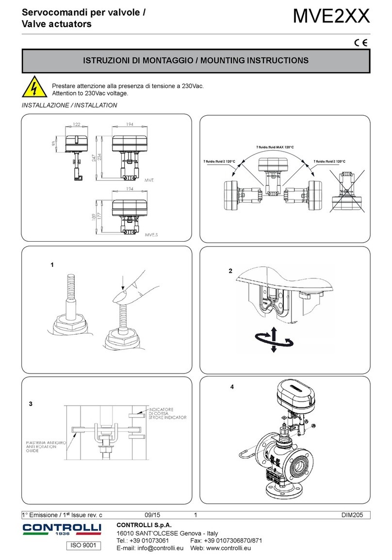
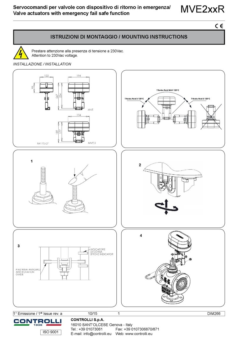
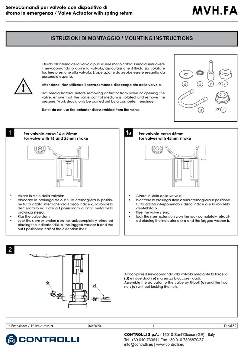
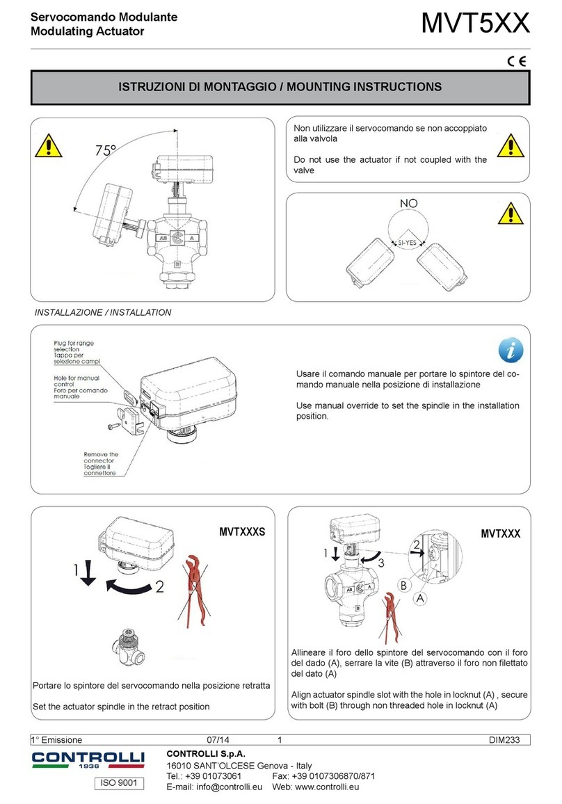
ISTRUZIONI DI MONTAGGIO / MOUNTING INSTRUCTIONS
Servocomando Modulante
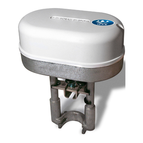
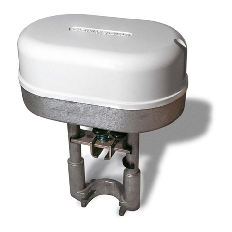
Modulating Actuator MVT5XX
Non utilizzare il servocomando se non accoppiato
alla valvola
Do not use the actuator if not coupled with the
valve
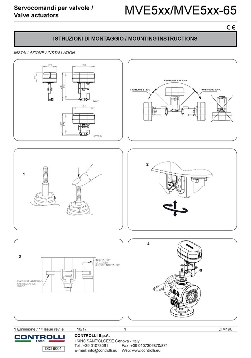
INSTALLAZIONE / INSTALLATION
Portare lo spintore del servocomando nella posizione retratta
Set the actuator spindle in the retract position
Allineare il foro dello spintore del servocomando con il foro
del dado (A), serrare la vite (B) attraverso il foro non lettato
del dato (A)
Align actuator spindle slot with the hole in locknut (A) , se-
cure with bolt (B) through non threaded hole in locknut (A)
MVTXXXS MVTXXX
Usare il comando manuale per portare lo spintore del co-
mando manuale nella posizione di installazione
Use manual override to set the spindle in the installation
position.
1aEmissione / 1st Issue rev. a 09/17 1 DIM233
ISO 9001
Sistemi di regolazione automatica per:
condizionamento/riscaldamento/processo termico industriale.
Le caratteristiche contenute in questa pubblicazione possono essere modifi cate senza preavviso
Automatic control systems for:
air conditioning/heating/industrial thermal process.
The performances stated in this sheet can be modifi ed without any prior notice
DIP OFF (DEFAULT) ON
1Azione DIRETTA / Direct
Action
Azione INVERSA / Rever-
se Action
2 Range 0-10V / 0-5V Range 2-10 / 6-10
3 No sequenza / No sequence Sequenza / Sequence
4 Corsa auto / Auto Stroke Corsa Fissa / Fixed Stroke
5Campi in Tensione / Voltage
range
Campi in Corrente /
4-20mA range
6Funzionamento Normale /
Normal running Apprendimento / Learning
SELEZIONE DIP SWITCH / DIP SWITCHES SELECTION
DESCRIZIONE DEI LEDS / LEDs DESCRIPTION
Selezine DIP attuatori a corsa ssa /
xed stroke actuators DIP selection
DIP 1 DIP 6
CORSA FISSA /
FIXED STROKE
[mm]
OFF OFF 5
OFF ON 5,5
ON OFF 2,5
ON ON 3,5
VALIDO SOLO PER DIP 4 IN ON
VALID ONLY IF DIP 4 IN ON
SCHEMI DI COLLEGAMENTO / WIRING DIAGRAMS
LED
FASE DI
APPRENDIMENTO
POSIZIONAMENTO
INIZIALE
POSIZIONAMENTO
UP
FINE CORSA UP
POSIZIONAMENTO
DOWN
FINE CORSA
DOWN
SERVOCOMANDO
FERMO
STALLO INATTESO
TENSIONE DI
ALIMENTAZIONE
BASSA
SERVOCOMANDO
SPENTO O
SOTTO RESET
(TENSIONE DI
ALIMENTAZIONE
BASSA)
FUNZIONE
LIMITE CORSA
MASSIMA
GIALLO ON ON ON ON ON ON ON ON LAMPEGGIANTE
1Hz OFF ON
ROSSO ALTERNATO
5Hz
ALTERNATO
1Hz
OFF OFF LAMPEGGIANTE
1Hz ON OFF CONTEMPORANEO
5Hz
OFF OFF ON
VERDE LAMPEGGIANTE
1Hz ON OFF OFF OFF OFF OFF ON
LEDs
CALIBRATION
PHASE
INITIAL
POSITIONING
UP
POSITIONING
END STROKE
UP
DOWN
POSITIONING
END STROLE
DOWN
ACTUATOR
STOP
UNEXPECTED
STALL
LOW SUPPLY
VOLTAGE
ACTUATOR
OFF OR
UNDER RESET
(SUPPLY
VOLTAGE LOW)
MAX STROKE
LIMIT PHASE
YELLOW ON ON ON ON ON ON ON ON BLINKING
1Hz OFF ON
RED ALTERNATING
5Hz
ALTERNATING
1Hz
OFF OFF BLINKING 1Hz ON OFF SIMULTANEOUS
5Hz
OFF OFF ON
GREEN BLINKING 1Hz ON OFF OFF OFF OFF OFF ON
Unire i cavi bianco e verde del nuovo servocomando e collegarli al
posto del cavo bianco del servocomando MVT56/57, il nuovo blu
al posto del vecchio verde e il nuovo rosso al posto del vecchio
marrone. Se ritenuto utile, è possibile usufruire del segnale di feed
back, non presente sul vecchio servocomando. Non eseguire i col-
legamenti elettrici, né effettuare eventuali interventi di modica degli
stessi in presenza di tensione.
Connect together the white and the green cable; then connect
the white cable of the new actuator in place of the white cable of
MVT56/57, the new blue cable in place of the old green cable and
the new red cable in place of the old brown cable..
If you need you can make use of the feedback signal, not available
on the old models of actuator. Do not make electrical connection or
changing operation in case actuators are powered.
SOSTITUZIONE VECCHI MVT PROPORZIONALI /
REPLACEMENT OF THE OLD PROPORTIONAL MVT
1aEmissione / 1st Issue rev. a 09/17 2 DIM233
This manual suits for next models

1

Other Controlli Controllers manuals

Controlli MDL46 User manual

Controlli

Controlli MDL46 User manual

Controlli MVE204S User manual

Controlli

Controlli MVE204S User manual

Controlli MVE5 R Series User manual

Controlli

Controlli MVE5 R Series User manual

Controlli NC7311 User manual

Controlli

Controlli NC7311 User manual

Controlli MVE522 User manual

Controlli

Controlli MVE522 User manual

Controlli MVC503R User manual

Controlli

Controlli MVC503R User manual

Controlli MVE5 R Series User manual

Controlli

Controlli MVE5 R Series User manual

Controlli MVC503 User manual

Controlli

Controlli MVC503 User manual

Controlli MVE2 Series User manual

Controlli

Controlli MVE2 Series User manual

Controlli MDL Series User manual

Controlli

Controlli MDL Series User manual

Controlli MVB User manual

Controlli

Controlli MVB User manual

Controlli MVE5 Series User manual

Controlli

Controlli MVE5 Series User manual

Controlli W554C User manual

Controlli

Controlli W554C User manual

Controlli MVE5 Series User manual

Controlli

Controlli MVE5 Series User manual

Controlli MVHFA User manual

Controlli

Controlli MVHFA User manual

Controlli MVE5-65 Series User manual

Controlli

Controlli MVE5-65 Series User manual

Controlli MVH56EA User manual

Controlli

Controlli MVH56EA User manual

Controlli Energon NR9001 User manual

Controlli

Controlli Energon NR9001 User manual

Controlli MVT203 User manual

Controlli

Controlli MVT203 User manual

Controlli MVE2 R Series User manual

Controlli

Controlli MVE2 R Series User manual

Controlli NR9000 User manual

Controlli

Controlli NR9000 User manual

Controlli MVE2XX User manual

Controlli

Controlli MVE2XX User manual

Controlli Energon User manual

Controlli

Controlli Energon User manual

Controlli MVH56EX User manual

Controlli

Controlli MVH56EX User manual

Popular Controllers manuals by other brands

LSIS XGL-EFMT user manual

LSIS

LSIS XGL-EFMT user manual

THOMSON TSC 80 - V2.2 Service manual

THOMSON

THOMSON TSC 80 - V2.2 Service manual

MSA 10033170 manual

MSA

MSA 10033170 manual

DALLEE ELECTRONICS LocoMatic 755 Installation and operating instructions

DALLEE ELECTRONICS

DALLEE ELECTRONICS LocoMatic 755 Installation and operating instructions

Mains MV4k/1 instructions

Mains

Mains MV4k/1 instructions

Kystar KLS4 manual

Kystar

Kystar KLS4 manual

Baldor VS1MD user manual

Baldor

Baldor VS1MD user manual

involight LEDCONTROL DMX512 user manual

involight

involight LEDCONTROL DMX512 user manual

Emerson HVAC Drive H300 Installation and commissioning guide

Emerson

Emerson HVAC Drive H300 Installation and commissioning guide

Auber Instruments EZboil DSPR120 instruction manual

Auber Instruments

Auber Instruments EZboil DSPR120 instruction manual

PPM Technology SPC-1 Operation manual

PPM Technology

PPM Technology SPC-1 Operation manual

Tamiya TEU-302BK quick start guide

Tamiya

Tamiya TEU-302BK quick start guide

YASKAWA GPD515C Technical manual

YASKAWA

YASKAWA GPD515C Technical manual

Midea KJR-120C/TF-E Installation & owner's manual

Midea

Midea KJR-120C/TF-E Installation & owner's manual

Comelit PAC 512 DCi instructions

Comelit

Comelit PAC 512 DCi instructions

Omron SGE Series manual

Omron

Omron SGE Series manual

MultiTrode MultiSmart Installation & operation manual

MultiTrode

MultiTrode MultiSmart Installation & operation manual

Murphy Selectronic Micro-Controller Series 1500 Specifications

Murphy

Murphy Selectronic Micro-Controller Series 1500 Specifications

manuals.online logo
manuals.online logoBrands
  • About & Mission
  • Contact us
  • Privacy Policy
  • Terms and Conditions

Copyright 2025 Manuals.Online. All Rights Reserved.