Duomo BX308 XP User manual

BX308XPGasDetectionController
t: 01905 797989
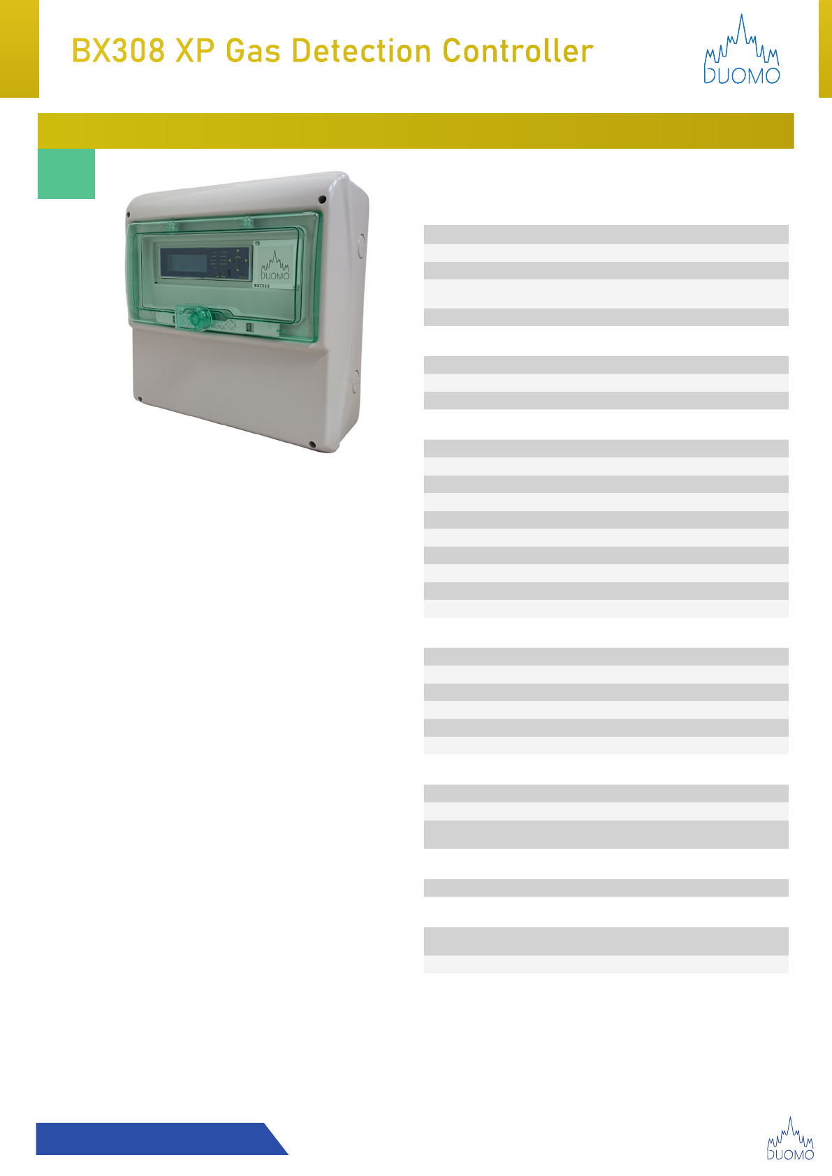
BX308 XP 8 Sensor Gas Detection Controller
FEATURES
■Eight sensors
■Datalogging Facility
■Wall mounted
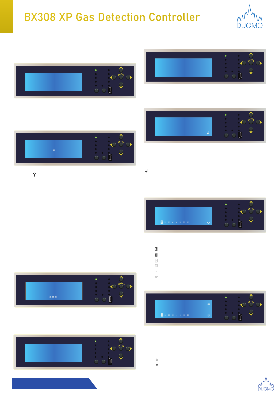
■Illuminated digital display
■Detection of Toxic 0-300ppm / Explosive Gas(es)
0-20%LEL
■4-20mA signal sensor input
■2 alarm stages - Pre-alarm and main alarm
■IP65 protective rating
■CE certied and approved to EN 50194 EN 50291 EMC
EN50270
■3 years guarantee
OVERVIEW
The control unit BX308 XP has been designed and built to meet
the current requirements of the Market and in compliance with
European Standard for checking gas presence in a versatile and
innovative using conventional sensors.
Up to 8 remote sensors from 4-20mA can be connected in
conventional mode for a single area. Gas concentration measured
by each sensor is sequentially shown on display, with a location
description.
When one of the connected sensors exceeds pre-alarm or main
alarm setpoints, the control unit activates the internal audible alarm,
depending on the concentration of gas measured, and shows on the
display the number of the sensor the amount of gas measured and
its origin; the alarm triggered is saved in a memory (Datalogger).
The data stored can be printed (up to maximum 50 events). The
control unit features two levels of alarm: 1st level, pre-alarm. This
data is variable. The technician can modify pre-alarm intervention
for every sensor according to the type of plant to be controlled.
The level can be selected from 5% to 9% of L.E.L. or from 75 to 135
ppm. Main alarm is set from 10-20 % of L.E.L. or 150-300ppm. The
control unit is equipped with a main alarm relay which can be set
with or without Positive Safety Switch to enable further independent
control of a solenoid valve. Finally, the control unit allows the user to
control the actual operation of the sensors coupled.
SPECIFICATION
Power
Power Supply 230V (enclosure) 12VDC module
Secondary Battery (Not supplied) 12VDC ± 10% Max 2.2Ah
Battery Charger Charger Capacity 2.2Ah
Power Consumption 12V - 25W Maximum
230V - 30W Maximum
Relay Contact Range 10A resistive 230VAC, 5A 30VDC resistive
Alarm Settings
Pre-Alarm No.1 Can be set from 5% LEL (75ppm) to 9% LEL (135ppm)
Main Alarm 10-20% LEL / 150-300ppm
Sensor Fault Short circuit, interruption, sensor deterioration
Technical Specication
Dimensions Width 360mm |Height 320mm |Depth 135mm
Weight 260 grams
Display Illuminated digital display
Mounting Wall & Panel mounted
Input Signal 4-20mA
Device Precision 1% FS
Reaction Time <2 seconds
Working Temperature -10°C to 45°C
Start-up Self-Diagnostic Delay 90 seconds
Protective Rating IP65
Conguration
Positive Safety Yes (General functions menu)
Main Alarm Relay Actuation Yes (General functions menu)
Gas Type Selection Yes (Sensors menu)
Timed Sensor Test Facility Yes
Emergency Stop Connections Yes
O2Compatibility as Standard Yes (Sensors menu) - Increase/Depletion
Perhipheral Specication
No. of Remote sensors 8 sensors
Maximum Sensor distance 100m
Cable Diameter for sensors 1mm2CSA
(Screened and earthed at the controller end)
Compatibility
Sensor Compatibility All Duomo Sensors (Explosive, toxic gas and oxygen)
Approvals, Certications and Guarantee
Approvals EN 61010-1, EN 50270, EN 50271, EN 45544-3,
EN 60079-29-1, EN 50104
Guarantee 3 years as standard
8
Sensor
Conventional
8888
Illuminated
Digital Display
4-20mA
IP65

BX308XPGasDetectionController BX308XPGasDetectionController
t: 01905 797989
1. This device can be set for For transverse sensitivities refer to the remote sensor user manual.
2. Response time T90: 1 second *
3. Temperature operating range: -10° C ÷ + 60° C
4. Humidity operating range: 0 ÷ 90% RH not condensed
5. Pressure operating range: 800 ÷ 1100 hPa
6. Power supply: 15 VDC
7. Absorption: 15W
8. Variable pre-alarm range: for explosive gases set for each probe between 5% and 9% of the LEL for Toxic gases
set from 75 to 135ppm
9. Variable alarm range 1: for explosive gases set for each probe between 10% and 20% of the LEL for toxic gases
alarms varying from 150 to 300 ppm
10. Variable alarm range 2: for explosive gases set for each probe between 10% and 50% of the LEL for toxic gases
alarms varying from 150 to 300 ppm
11. ATEX protection: this device must be installed in NON-CLASSIFIED ATEX areas.

BX308XPGasDetectionController
t: 01905 797989
TEST RESET
Pre Alarm
Main Alarm
Exit Alarm
Siren Status
Made in Italy
Power
Battery
OL Probes
OL Battery
Fault
4 5321 6 87
4 53210v 0v6 87
21 43 65
4 532 8 9761 10 11
BX308
TEST RESET
Pre Alarm
Main Alarm
Exit Alarm
Siren Status
Made in Italy
Power
Battery
OL Probes
OL Battery
Fault
4 5321 6 8721 43 65
4 532 8 9761 10 11
Dimensions

BX308XPGasDetectionController
t: 01905 797989
Overview
The BX308xp is a control unit capable to control the concentration of gas up to 8 input channels, each of which can
be connected via a 4-20 mA communication to a toxic, explosive or oxygen gas detection sensor. The control unit is
built with the following I/O interfaces.
- Power supply 110/240 VAC
- Controls up to 8 remote sensors,
- Manages explosive and toxic gases.
- Manges up to 8 remote expansion cards: relay card
- Manual alarm managed by remote button
- Various possibilities of parameter conguration
- Status indications with LED
- Output signals in alarm supplied via 4 relays.
- Fault output signals supplied via 1 relay
- Output signals in fault supplied via 1 relay
- Output signals for the external siren supplied via 1 relay
- Wall support 9 DIN modules.
- Conforms to the operating regulations EN60079-29-1
BX308xp status conditions
Depending on the input signal of the remote sensors, the control unit can be found in the following working conditions:
NORMAL MODE: Controller is receiving signal from the sensors corresponding to a gas level of 0-9% of LEL (explosive
gases) and 0-300 ppm (toxic gases). Buzzer and Relays are off and no alarm or fault LEDs illuminated.
PRE-ALARM: Controller is receiving signal from the sensors corresponding to an explosive gas level of 5-9% of LEL
(explosive gases) for toxic gases set from 75 to 135ppm (toxic gases). The relays switch and the red pre-alarm LED is
illuminated. The buzzer sounds and the display shows the % of gas detected.
1st ALARM: the control unit receives a signal from the sensors corresponding to an explosive gas level set for each probe
between 10% and 20% of the LEL; for toxic gases set from 150 to 300 ppm. The relays switch and the red general alarm
LED lights up. The buzzer sounds and the display shows the % of gas detected.
2nd ALARM: the control unit receives a signal from the sensors corresponding to an explosive gas level set for each probe
between 10% and 50% of the LEL; for toxic gases set from 150 to 300 ppm. The relays switch and the red general alarm
LED lights up. The buzzer sounds and the display shows the % of gas detected.
MAIN ALARM: the control unit receives a signal from the sensors corresponding to a gas level higher than 20% LEL for
explosive gases and greater than 300 ppm for toxic gases. The main alarm relay also changes state and the red "20/300"
LED also lights up, the "General alarm" LED flashes. The general alarm relay is energized. The buzzer is on (high frequency).
OVER / UNDER RANGE: the control unit receives an under / over range signal. This condition is signaled by two different
flashing frequencies of the explosive gas LEDs. The relays are off and no alarm or fault LED lights up. The buzzer is off.

BX308XPGasDetectionController
t: 01905 797989
Precautions
TERMS & EXPECTATIONS: The installation, service and removal at the end of its functional life of the
BX308xp guaranteed by the manufacturer, must be carried out by authorised and capable personnel.
Be sure to disconnect the controller from the power supply before making changes to the connections. After making
all the connections and configurations, the system can be powered up
Check the integrity of the sensor after having removed it from the box.
Check that the power supply to be supplied to the appliance is compatible with the limits illustrated above. When doing
the electrical connections, follow the drawing closely.
Any use of the detector for purposes other than the intended one is considered improper, and as a result of which
Duomo (UK) therefore disclaims any responsibility for possible damages caused to people, animals or objects.
IMPORTANT: Function testing should be carried out with calibrated test gas to ensure sucient and safe gas
concentration to activate the main alarm.
WARNING!
• This control unit is NOT built for installation in ATEX classified areas
• To meet the requirements as a control unit according to the standard EN 60079-29-1: 2016
• Duomo (UK) has relied on programming and functions via a microprocessor with a numeric alpha display
• All the wiring of the remote sensors must be made using wires with a minimum section of 1.5 mm2 and no
longer than 100m. Do not use the same conduit for signal and power cables.
• If strong EMC disturbances are present the use of shielded cables is strongly recommended. The screen must
be connected to the 'Gnd' terminal of the interested area only on the side of the control unit.
• The appliance must be connected to the power supply by means of a switch capable of disconnecting the poles
in compliance with current safety standards and with a contact.
• separation of at least 3 mm in all poles.
• The installation and electrical connections of this appliance must be carried out by qualified personnel.
• technicians and in compliance with the current technical and safety standards.
• Be sure to turn off the power before wiring the device.
• Safety depends on the installer (whose responsibility is to set up a detection system in compliance with existing
standards, both European and national) to choose the correct type of loads to be connected to the control unit
and the correct configuration of the system parameters.
• In case of doubt, please contact the distributor.
Keep in mind the following precautions to keep the BX308xp in good working order
• Do not allow it to become wet.
• The control unit is not waterproof if immersed in water or exposed to high humidity, it can be seriously damaged.
• Do not drop it.
• Heavy knocks or falls during transportation or installation can damage the appliance.
• Avoid abrupt temperature uctuations.
• Sudden temperature variations can cause condensation and the probe could work poorly.
• Never clean the device with chemical products. If necessary, wash with a moist cloth.

BX308XPGasDetectionController
t: 01905 797989
Interface
1. MAINS Illuminated when BX308xp is powered by mains voltage.
2. Battery Illuminated when BX308xp is powered by battery, Flashes when battery voltage is less than 10.8 V
3. PROBE OVER LOAD Illuminates when short circuit or a high absorption of current by the sensor and the relative
connection cables. Check the battery and the connection cables.
4. BATTERY OVER LOAD Illuminated when battery is connected incorrectly or there is an abnormal current
absorption. Check the battery and the connection cables.
5. FAULT Illuminated and ashes when a connected sensor is faulty, the connection cables are interrupted, or there
is a connection error. When this LED is on, the device is no longer able to detect and activates all the relays, both
on the 1st threshold and on the 2nd threshold. To restore the operation, sensor must be repaired or removed using
the setting program and the RESET button must be pressed. This signal is type "autoreset"
6. PRE-ALARM LED (PRE-ALARM) Illuminated when the gas concentration level has reached the pre-alarm
threshold, which can be modied by the user (see Status conditions).
7. MAIN ALARM (GENERAL ALARM) Illuminated when the concentration level of the gas has reached the main
alarm threshold, which can be modied by the user (see Status conditions).
8. EXIT ALARM Illuminated when you press the remote alarm button, at the same time the word "BTN" appears on
the display
9. EXTERNAL SIREN LED for activating the EXTERNAL SIREN. Illuminates RED when external siren is
disconnected. (Access to this function requires password).
10. TEST button Pressing and holding this button simulates a gas leak.
11. RESET button Press this button to reset all memories.
12. Printer USB port Connection to print the data stored in the memory.
13. Restart button It is used to Reset the control unit without having to remove primary voltage.
14. Expansion card connection Quick-t socket for inserting expansion cards. cod. CARD-RLS4 Relay expansion
card, cod. CARD-BMS16 conversion board from current to voltage
External manual alarm button.
The control unit is designed to be connected to a manual alarm button. Pressing the button the control unit will go
directly into alarm even when it is in the programming state or warm up, closing all the auxiliaries connected to it.
When pressed on the message "alarm activated by external button" is displayed on LCD.
TEST RESET
Pre Alarm
Main Alarm
Exit Alarm
Siren Status
Made in Italy
Power
Battery
OL Probes
OL Battery
Fault
4 5321 6 87
4 53210v 0v6 87
21 43 65
4 532 8 9761 10 11
1
abc
fgh
i
de
2
3
4
14
5
6
7
8
12
9
10 11
13
Connections & Interface

BX308XPGasDetectionController
t: 01905 797989
(a) Main power supply (1 positive, 2 negative)
(b) Backup power supply (3 positive, 4 negative)
(c) Sensor power supply (5 positive, 6 negative)
Warning: Optional battery charged directly from
controller
(d)
Terminal 1: Sensor 1 return signal
Terminal 2: Sensor 2 return signal
Terminal 3: Sensor 3 return signal
Terminal 4: Sensor 4 return signal
Terminal 5: Sensor 5 return signal
Terminal 6: Sensor 6 return signal
Terminal 7: Sensor 7 return signal
Terminal 8: Sensor 8 return signal
Warning:
• 8 sensors can be connected across 1 zone
• Sensors must conform to 4-20mA current loop
system
(f)
Terminal 1,2,3: Main alarm
Terminal 4,5: Pre Alarm
(g)
Terminal 6,7: Fault
Terminal 8,9: External Siren
(h)
Knock o button connection
Connections
Sensor Connections
Relay Connections
Expansion Cards
21 43 65
+ - + - + -
Power supply
12-15v
Battery
12-15v
Sensor Power
Supply
a
b
c
4 5321 6 87
d
Sensor 1 to 8 Return voltage
3 2 1 3 2 1 3 2 1 3 2 1 3 2 1 3 2 1 3 2 1 3 2 1
Sensor
1
Sensor
2
Sensor
3
Sensor
4
Sensor
5
Sensor
6
Sensor
7
Sensor
8
4 5321
f
C C
NC
Main Alarm Pre Alarm
NC
NO NO
f
C
Fault
NC
NO
Siren
NC
NO
C
8 976
g
10 11
h
(Up to 8 expansion cards can be connected (relay
card CARD-RLS4), having 4 relays each.
The relays can be associated with the desired probe
Each relay can be associated with the following
functions: Pre-Alarm, Alarm, Fault or not used
See 14 on previous 'Connections and Interface' page

BX308XPGasDetectionController
t: 01905 797989
Pre Alarm
Main Alarm
Exit Alarm
Siren Status
Power
Battery
OL Probes
OL Battery
Fault
Time Settings
General Functions
Exit
Input Settings
Pre Alarm
Main Alarm
Exit Alarm
Siren Status
Power
Battery
OL Probes
OL Battery
Fault
Date Time
23/Au /22 14 : 36
g
Pre Alarm
Main Alarm
Exit Alarm
Siren Status
Power
Battery
OL Probes
OL Battery
Fault
Sensor Configuration
1 2 3 4 5 6 7 8
Pre Alarm
Main Alarm
Exit Alarm
Siren Status
Power
Battery
OL Probes
OL Battery
Fault
Insert Password
0 1 2 3 4 5 6 7 8 9
Probe settings
1 2 3 4 5 6 7 8
Memory ON
1 2 3 4 5 6 7 8
▼▲ - Choose menu option
ENTER - Select option
Main Menu
Input Settings
◄► - Select (Day/Month/Year or Hour/Minute) option
ENTER - Increment selected date or time
ENTER (HOLD) - Cycle through available options much
quicker
Select to return to MAIN MENU
◄► - Select Sensor
ENTER - Select Memory ON/OFF
(OFF for toxic sensors only)
ON - Controller requires manual reset (RESET button)
OFF - Controller Auto resets (<50ppm)
Return to Probe Settings
Continue to Pre Alarm
◄► - Select Sensor
ENTER - Change selected sensor between
Explosive
Toxic
Oxygen
CO2 sensor
No connected sensor
Continue to Memory
Time Settings
Sensor Settings
Memory Settings
Controls & Navigation
Pre Alarm
Main Alarm
Exit Alarm
Siren Status
Power
Battery
OL Probes
OL Battery
Fault
SN 00084 23/Au /22
State 11:44
Exp 020%Sensor 01
00.0%LEL __________
g
Pre Alarm
Main Alarm
Exit Alarm
Siren Status
Power
Battery
OL Probes
OL Battery
Fault
Duomo SN 000846
23/Au /22 10:45
v.4.2 ==== BX308XP
Countdown: 90
g
Pre Alarm
Main Alarm
Exit Alarm
Siren Status
Power
Battery
OL Probes
OL Battery
Fault
Insert Password
0 1 2 3 4 5 6 7 8 9
◄► - Choose password digits (Default password is 1234)
ENTER - Select digits
Successful password input displays MAIN MENU.
This display appears when BX308xp is powered up with a 90
second warmup countdown, Main Screen is then displayed.
Initial Screen
Warmup
ENTER - Sensor display lock ON/OFF
: Locked sensor display
- : Cycles active sensors every 8 seconds
ENTER (HOLD 5 seconds) - Access MAIN MENU
◄► - Accelerate current sensor being displayed
On Display
• Display has Registration number
• Date & Time
• Work State
• Currently monitored sensor
• Target gas
• Explosive or Toxic sensor
• L.E.L or ppm sensor value
• Bar graph of gas level
ENTER Password
Pre Alarm
Main Alarm
Exit Alarm
Siren Status
Power
Battery
OL Probes
OL Battery
Fault
Time Settings
General Functions
Exit
Input Settings

BX308XPGasDetectionController
t: 01905 797989
ENTER - Select to return to MAIN SCREEN
Exit
Pre Alarm
Main Alarm
Exit Alarm
Siren Status
Power
Battery
OL Probes
OL Battery
Fault
Alarm 20%LEL-20
1 2 3 4 5 6 7 8
Prealarm 09%LEL
1 2 3 4 5 6 7 8
Pre Alarm
Main Alarm
Exit Alarm
Siren Status
Power
Battery
OL Probes
OL Battery
Fault
Alarm 20%LEL-20
1 2 3 4 5 6 7 8
Pre Alarm
Main Alarm
Exit Alarm
Siren Status
Power
Battery
OL Probes
OL Battery
Fault
Op Range 20%LIE
1 2 3 4 5 6 7 8
◄► - Select Sensor
ENTER - Choose Pre alarm settings for selected sensor
Return to Memory Settings
Continue to Alarm
◄► - Select Sensor
ENTER - Choose Alarm settings for selected sensor
Return to Pre Alarm
Continue to OP Range
◄► - Select Sensor
ENTER - Choose Alarm settings for selected sensor
Note: Oxygen sensors operating range is factory set to 20%
Given the importance of this operation a confimation screen
will appear. Select between YES/NO with ENTER
The operating range will change from 20% to 100% of LEL.
Remember to change Sensor too.
Return to Alarm
Select to return to MAIN MENU
Pre-alarm Settings
Alarm Settings
OP Range Settings
General Settings
Pre Alarm
Main Alarm
Exit Alarm
Siren Status
Power
Battery
OL Probes
OL Battery
Fault
Relay: Continuous
Siren: ON
Buzzer: ON
Positive Safety: ON
▼▲ - Choose menu option
ENTER - Choose settings
Relay: CONTINUOUS/PULSED
Continuous: Relay remains closed for entire duration
of alarm condition (If memory is selected, the relay
will remain switched until RESET button is pressed)
Pulsed: The relay reamins closed for 20 seconds, after
which it is de-energised
Positive Safety: ON/OFF
Depending on the type of system, there may be a need to
select Positive Safety. In this mode the operation of the two
manual alarm relays is reversed.
Selection
Use the ▼▲ keys to select the Sic message. Positive Safety.
Each time the "ENTER" button is pressed, the ON / OFF
message will change.
In the "ON" position, the Positive Safety function is activated.
In the "OFF" position, the Positive Safety function is
deactivated.
Once chosen, move with the ▼▲ buttons on the next
selection.
Siren: ON/OFF
Select the word Siren with the ▼▲ keys
Each time the "ENTER" button is pressed, the ON / OFF
message will change.
In the "ON" position the Siren is enabled; The LED on the
panel goes out.
In the "OFF" position the Siren is silenced; The LED on the
panel lights up.
Buzzer: ON/OFF
Select the word Buzzer with the ▼▲ keys
Each time the "ENTER" button is pressed, the ON / OFF
message will change.
In the "OFF" position the Buzzer is silenced.
In the "ON" position the Buzzer is enabled.
Continue to Advanced Settings

BX308XPGasDetectionController
t: 01905 797989
Advanced Functions
▼▲ - Choose menu option
ENTER - Choose advanced functions
Move with the ◄► buttons over the desired number
and press "ENTER", each time the number selected will
light up. Proceed with the insertion until all four numbers
are turned on.
Once entered, the word "CONFIRMED" lights up.
Memorize your password and don't forget it! If you forget
your password you can find the "PUK" number written on
the warranty sheet.
From this moment, to access the ECU programming, the
new Password must be entered. After the change the
program switches to the next function. "Data logger”
Move with the ▼▲ buttons using either x1 or x10 to
advance through events.
All security and general fault events are stored in the data
logger, including network blackouts, battery operation or
discharge, etc.
All data is stored with codes, each code corresponds to an
event. See table below for error code event types:
Process to functional control the gas detection sensors.
Conventional probes transmit the signal to the control unit in
current from 4 to 20 mA values.
4 mA - No gas
20 mA - Gas alarm level threshold.
In the start-up phase the cursor positions itself on sensor 1.
Voltage and the current detected by the sensor is displayed.
Move to desired sensor with the ◄► buttons
This ensures that gas flow is not interrupted during
maintenance operations and inhibits the external siren.
The interruption period is managed directly by the technician
based on the size of the installation. Position yourself above
the word: "maintenance: 00"
Press "ENTER" button to adjust the maintenence time period
(15 - 30 - 45 - 60 minutes)
N.B. At the end of the countdown the device returns to
normal operating status. During the maintenance period "in
Maintenance" and remaining minutes are displayed.
Maintenance interruption
If the job ends before the set time, pressing the "RESET"
button exits the maintenance cycle.
Functional test
A function test should be carried out every 6 months
minimum. Using calibration gas of the target gas over the
level of the alarm threshold the sensor can be tested. This
teset the sensor is reacting and the the correct functions are
activated by the controller.
At least once a year A more accurate check must be
carried out by a specialised technician who must issue the
verification certificate with the Duomo TS1007 tester.
The decommissioning of the system must be carried out by
a specialised technician.
Pre Alarm
Main Alarm
Exit Alarm
Siren Status
Power
Battery
OL Probes
OL Battery
Fault
Advanced Functions
Pre Alarm
Main Alarm
Exit Alarm
Siren Status
Power
Battery
OL Probes
OL Battery
Fault
Change password
Print
Test probes
Datalogger
Pre Alarm
Main Alarm
Exit Alarm
Siren Status
Power
Battery
OL Probes
OL Battery
Fault
V=00.6V I=04.0mA
12345678
Change password
Datalogger
Test Probes (Sensors)
Maintenence Program
Type of Event Code
1 Pre-alarm E00-S01
2 Alarm E01-S01
3 Generic Fault Sensor E02-S01
4 Black Out E03-C00
5 Voltage Recovery E04-C00
6 Low Battery E05-C00
10 Sensor off E09-S01
11 Device Reset E10-C00
12 Clock Battery E11-C00

BX308XPGasDetectionController
t: 01905 797989
Up to a maximum of 16 CARD-RLS4 Relay Expansion cards
can be connected to the control unit.
On each board there are 4 auxiliary relays, to be associated
with the desired probe. With a maximum of 64 relays.
The functions related to: Pre-Alarm, Alarm, Fault or not used
can be associated to each selected relay
Each selected relay can be associated with a specific range
of probes from 1 to 16.
CARD-RLS4- Indicates the address set in the card in reading.
Each time the ENTER button is pressed, the
CARD-RLS4 card to be set is selected.
Relay - Each press of "ENTER" chooses the Relay (from 1 to
4) to which you want to associate a function.
Func. With each press of "ENTER" choose the function to
associate: not used-pre-alarm-alarm-failure
PROBE. Each press of "ENTER" chooses the interval of the
sensors to which I must associate the function of the relay
Pre Alarm
Main Alarm
Exit Alarm
Siren Status
Power
Battery
OL Probes
OL Battery
Fault
Advanced Functions
Relay Expansion cards
Warning! Factoy reset erases all user-entered data.
Select “Factory reset”, Pressing “ENTER” the writing
starts to flash.
Hold down “ENTER” for 4 seconds, a grid appears with
10 empty rectangles that gradually fill up, at the end of
which the BX308xp is totally reset, and starts a new 90
second warm up countdown.
Factory Reset

BX308XPGasDetectionController
t: 01905 797989
Sensor positioning
The BX308xp is a safety device designed to give audible
alarms and automatically provide latched electrical isolation
of associated gas safety shut o valves in the event of a gas
leak or build up of toxic gases.
The sensors can be located up to 100m from the gas detector.
Cable size should be 1mm2CSA. If the sensor cables are
run separately in specic conduit it is not essential to use
screened cable but if the cables are routed through conduit
or trunking containing other wiring the use of screened cable
is advisable. The wiring should be performed by a qualied
person in accordance with current regulations. The plug-in
terminal rail makes installation easy and quick. Do not mount
close to any heat source or in an area where moisture is
likely to eect operation. The IP rating of this unit is IP44.
Sensors should be positioned as shown below.
If you require any guidance on this please call Duomo
technical support on +44 1905 797989.
Sensor Sensor type IP Rating Zone suitability Target gas Working range Output Accuracy Auto
Calibration
Relay
SG500 Catalytic IP30 Safe Area CH4 / LPG 0-100% LEL 4-20mA +/- 5% No No
SG544 Catalytic IP44 Safe Area CH4 / LPG 0-100% LEL 4-20mA +/- 5% No No
SGM595 Catalytic IP55 Safe Area See catalist 0-100% LEL 4-20mA +/- 5% Yes No
SGM595/A Catalytic IP66 Zone 2 NE See catalist 0-100% LEL 4-20mA +/- 5% Yes No
SGM533 Catalytic IP55 Safe Area See catalist 0-100% LEL 4-20mA +/- 5% Yes Yes
SG800 Catalytic IP66 Zone 2 NE See catalist 0-100% LEL 4-20mA +/- 5% Yes Yes
SG870 Optical Flur. IP64 Zone 2 NE Oxygen In % 4-20mA +/- 5% Yes Yes
SG880 Infrared IP66 Zone 2 NE CO2 0-100% LEL 4-20mA +/- 5% Yes Yes
HCF100 Semiconductor IP55 Safe Area Freon/Ammonia 0-300 ppm 4-20mA +/- 5% No Yes
SG895 Catalytic ATEX Hazardous Area See catalist 0-100% LEL 4-20mA +/- 5% Yes No
SG580 Catalytic IP66 Zone 2 NE See catalist 0-100% LEL 4-20mA +/- 5% No No
SGF100 Catalytic IP64 Zone 2 NE CH4 0-100% LEL 4-20mA +/- 5% Yes Yes
SGF102 Catalytic IP64 Safe Area CH4 / LPG 0-100% LEL 4-20mA +/- 5% Yes Yes
SGF104 Optical Flur. IP64 Safe Area CH4 / LPG 0-100% LEL 4-20mA +/- 5% Yes Yes
SGF106 Semiconductor IP64 Safe Area CH4 / LPG 0-300 ppm 4-20mA +/- 5% Yes Yes
SGF108 Electrochemical IP64 Safe Area CH4 / LPG 0-300 ppm 4-20mA +/- 5% Yes Yes
SGF110 Electrochemical IP64 Safe Area CH4 / LPG 0-300 ppm 4-20mA +/- 5% Yes Yes
SGF112 Catalytic IP64 Safe Area CH4 / LPG 0-100% LEL 4-20mA +/- 5% Yes Yes
CO100r Electrochemical IP55 Safe Area CO 0-300 ppm 4-20mA +/- 5% Yes Yes
CO100Ar Electrochemical IP66 Zone 2 NE CO 0-300 ppm 4-20mA +/- 5% Yes Yes
SG800 Duct Catalytic IP66 Zone 2 NE CH4 / LPG 0-100% LEL 4-20mA +/- 5% Yes Yes
SG800 Electrochemical IP66 Zone 2 NE CO 0-300 ppm 4-20mA +/- 5% Yes Yes
Compatible Sensors

Troubleshooting
The Problem The Solution
If the device does not start up. Check that the power supply is correctly connected. If powered by the battery, check that the
is power is
correctly connected.
If the Fault LED lights up, the system reports
an error status.
Possible cause: The input current loop is interrupted or the sensor is not powered.
Solution: Check the connections between the sensor and the control unit for interruption. Also
check presence of a voltage around 12 VDC between the "+ V" and "GND" terminals of the
reference input.
If the Over Load Probe LED lights up. Check that the power polarity has not been inverted, that no short-circuit is present, that the
sensors were not damaged during installation, that no excessive current absorption is present.
If the Over Load Battery LED lights up. Check that the connection cables are not short-circuited, that the polarity has not been
inverted, or that the battery is not damaged.
If the control unit is repeatedly issuing an
alarm.
Check that there are no gas leaks.
If the alarm signal and the FAULT indicator light turn on together, check the sensors.
If the control unit is issuing an alarm and
does not shut o the devices connected to
it.
Check that the wiring is correct and that the jumper that carries power to the relay has
been set properly. All relays must be free from electrical power. Check the drawing of the
connections.
If a 12Vdc solenoid valve is connected to the
BX308/xp, which does not work well
Direct connection of 12Vdc solenoid valves or sirens to the BX308xp is not permitted.
An external power unit must always be used. The BX308xp gives a max current of 200mA.
In case of alarm
Extinguish any naked ames.
Do not switch lights or electrical devices on or o.
Open all windows and door to increase ventalation.
• If the ALARM LED is o the levels of gas have dropped. A responsible, qualied person is now safe to nd the cause of the alarm.
• If the alarm sound reamins constant and the cause is not evident or not possible to eliminate turn o the emergency isolation valaves to the area
and contact your gas provider emergency line. They will advise accordingly.

www.duomo.co.uk
sales@duomo.co.uk
01905 797989
5 The Furlong, Berry Hill Industrial Estate, Droitwich, Worcestershire, WR9 9AH
GAS SAFETY CONTROLS
@DuomoUK
linkedin.com/company duomo-uk
BX308xp 02102023 rev5
This document is protected by copyright ©
No changes by others are permitted without prior authorisation by Duomo (UK) Ltd.
Duomo (UK) Ltd reserve the right to modify and revise this datasheet without notication.
Table of contents
Other Duomo Controllers manuals