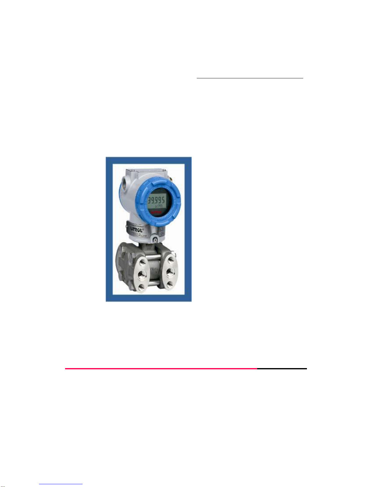
APT3700N Smart Pressure Transmitter for Nuclear Service Operation Manual M3700N-K01E
6
Table of Contents
1. Introduction ...............................................................................................................8
1.1. Overview … ………………………………………………………………….……..8
1.2. Smart Pressure Transmitter ………………………………………………………8
2. Installation …………………………………………………………………………………11
2.1. Overview …………………………………………………………………………….11
2.2. General Consideration ……………………………………………………………..11
2.3. Mechanical Consideration ………………………………………………………….11
2.3.1. Process Connection …………………………………………………………12
2.3.2. Conduit ……………………………………………………………………….13
2.4. Electric Consideration ………………………………………………………………14
2.4.1. Power Supply and Load Resistance ………………………………………17
2.5. Install Consideration ………………………………………………………………..18
2.5.1. Mechanical …………………………………………………………………...18
2.5.2. Electronic ……………………………………………………………………..18
3. Calibration ………………………………………………………………………………….21
3.1. Overview ……………………………………………………………………………..21
3.2. ZERO …………………………………………………………………………………21
3.3. ZERO Adjustment …………………………………………………………………..22
3.4. ZERO Trim …………………………………………………………………………..23
3.5. SPAN …………………………………………………………………………………23
3.6. Damping Adjustment ……………………………………………………………….24
3.7. Button Function ……………………………………………………………………..25
4. OPERATION ………………………………………………………………………………31
4.1. Overview …………………………………………………………………………….31
4.2. Transmitter Operation & Sensor ………………………………………………….32
4.3. Transmitter's Max Electricity ………………………………………………………33
4.4. Safety of Inserting in Reverse Direction ………………………………………….33
4.5. Installation Place ……………………………………………………………………34
4.6. Conditions after Installation ………………………………………………………..34
4.7. Connecting to Pressure …………………………………………………………….34
4.8. Wireless Transmitter's Limitations ………………………………………………...35