Duplo INSTRUCTION MANUAL User manual

INSTRUCTION MANUAL
SYSTEM5000
Dynamic Booklet Maker
DBM-500
[ for 120 V ]
Be sure to read this manual prior to use.
Please leave this manual at the site of use for easy reference.

Applicable to the 120 V machine
This equipment has been tested and found to comply with the limits for a Class A digital device, pursuant to Part 15 of the FCC
Rules.
These limits are designed to provide reasonable protection against harmful interference when the equipment is operated in a
commercial environment.
This equipment generates, uses, and can radiate radio frequency energy and, if not installed and used in accordance with the
instruction manual, may cause harmful interference to radio communications.
Operation of this equipment in a residential area is likely to cause harmful interference in which case the user will be required
to correct the interference at his own expense.

1
1. SAFETY PRECAUTIONS................................ 2
2. USAGE PRECAUTIONS ................................. 5
2-1. Power Supply ..................................................5
2-2. Operating Environment ................................... 5
2-3. Storage Conditions ......................................... 5
3. NAMES AND FUNCTIONS ............................. 6
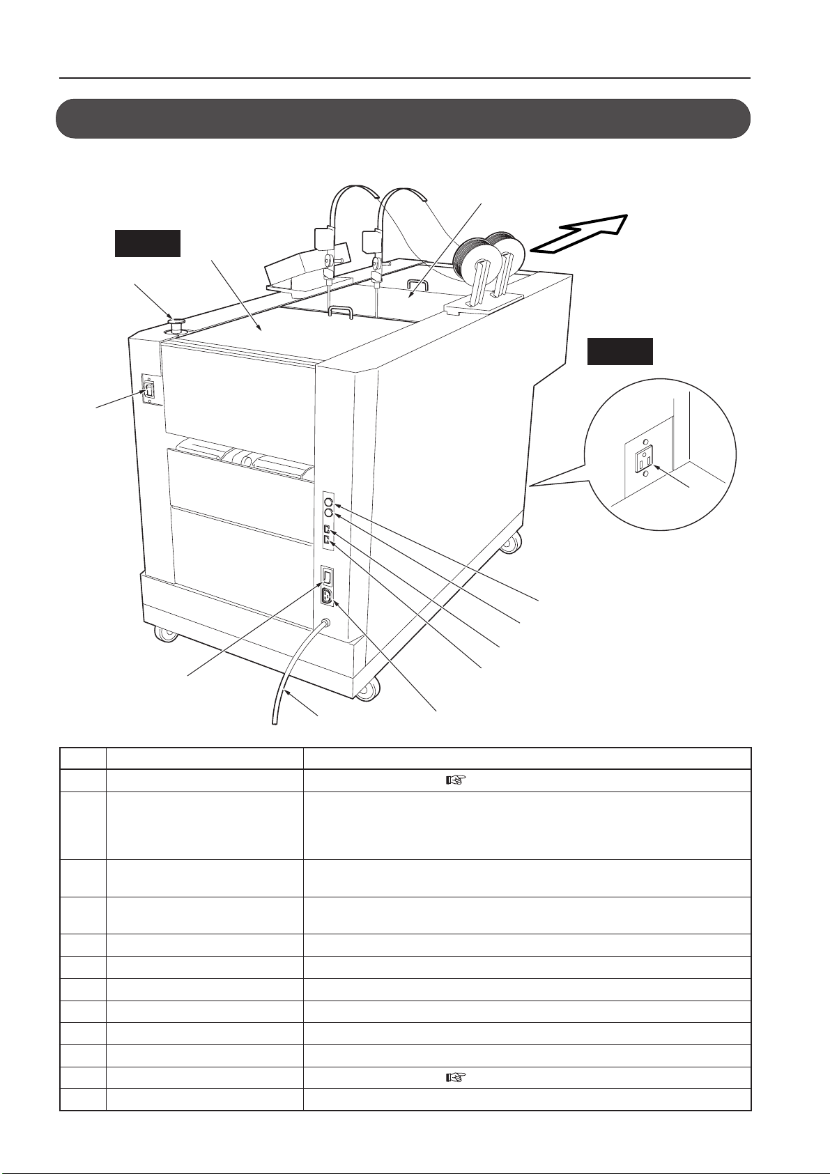
3-1. External Parts ................................................. 6
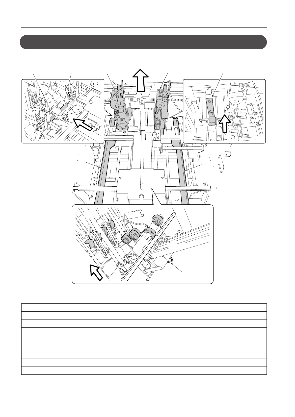
3-2. Internal Parts...................................................8
3-3. Downstream Unit (Optional)..........................11
3-4. Accessories...................................................11
4. NAMES AND FUNCTIONS OF CONTROL
PANEL (MAIN MENU)................................... 12
5. PREPARING FOR OPERATION................... 14
5-1. Power ON ..................................................... 14
5-2. Operations ....................................................15
5-3. Settings .........................................................19
6. SADDLE STITCHING PROCEDURE ............ 27
6-1. Settings .........................................................27
6-2. Changing Size............................................... 30
6-3. Adjustments Using the Step Mode................30
6-4. Checking the Finished Set ............................33
7. SIDE STITCHING/CORNER STITCHING
PROCEDURE ................................................ 38
7-1. Settings .........................................................38
7-2. Changing Size............................................... 41
7-3. Adjustments Using the Step Mode................42
7-4. Checking the Bound State ............................45
8. NO-STITCHING FOLDING PROCEDURE ... 46
8-1. Settings .........................................................46
8-2. Changing Size............................................... 48
8-3. Adjustments Using the Step Mode................49
8-4. Checking the Finished Set ............................52
CONTENTS
Thank you for purchasing this Duplo equipment. To ensure correct usage, please read this
instruction manual thoroughly, especially the section entitled "Safety Precautions".
The aim of this instruction manual is to ensure safe and proper use of the equipment.
For this reason, do not attempt to remodel, modify or adapt this equipment or to use it for any other
purpose than that intended by the manufacturer.
After reading, please keep this instruction manual handy for future reference.
9. VARIOUS SETTINGS.................................... 56
9-1. Fine Adjustment Menu .................................. 56
9-2. Option Menus................................................ 61
9-3. Accessory Menus.......................................... 63
9-4. Adjusting the Press Pressure and Conveyance
Pressure........................................................ 66
9-5. Adjusting the Saddle Stitching Guide/Side
Stitching Guide.............................................. 66
10. ERROR MESSAGES..................................... 67
10-1. Emergency Stop ...........................................67
10-2. Covers...........................................................67
10-3. Paper Jam.....................................................68
10-4. Wire Feed Detection ..................................... 68
10-5. Paper Tray Full .............................................68
10-6. Motor Error .................................................... 69
10-7. Service Person Error.....................................69
10-8. Shutter ..........................................................69
11. CORRECTING PAPER JAMS ...................... 70
12. STITCHER HEAD .......................................... 71
12-1. Names and Functions ................................... 71
12-2. Wire...............................................................72
12-3. Feeding the Wire........................................... 73
12-4. Stitching Tests ..............................................75
12-5. Removing Wire .............................................76
12-6. Adjustments ..................................................77
12-7. Maintenance .................................................78
13. TROUBLESHOOTING .................................. 79
14. CLEANING .................................................... 81
15. SPECIFICATIONS ......................................... 82
INTRODUCTION

2
Always observe the cautions and warnings given below to prevent personal injury or property
damage.
The degree of danger and damage that could occur is indicated on two levels by the
following marks.
WARNING: Ignoring this mark could result in the possibility of serious injury
or even death.
CAUTION: Ignoring this mark could result in the possibility of injury or
physical damage.
The following graphic symbols indicate the various types of action to be performed
or avoided.
This graphic symbol indicates a forbidden action.
means “Do not disassemble.”
means “Do not touch.”
This graphic symbol indicates actions that must be performed.
means “Disconnect the power plug.”
WARNING:
Do not place metal objects or vessels containing liquids on top of the unit. The entry of
any metal object or liquid could result in a fire or an electrical shock.
Do not insert any metal or easily-combustible object inside this unit. This could result in
a fire or an electrical shock.
Do not touch or insert foreign objects into any rotating part during operation. This could
result in injury.
Do not remove the cover or back panel. This unit contains high-voltage components that
could cause an electrical shock.
Do not disassemble, modify or repair this unit. There is a danger of fire, electrical shock
or injury. Contact your dealer when repairs are necessary.
Use only the power supply voltage specified on the main nameplate. Using other
voltages could result in a fire or an electrical shock.
Keep this unit and the power cord away from heaters and heater vents. Excessive heat
could melt the cover or power cord covering, and result in a fire or an electrical shock.
1. SAFETY PRECAUTIONS

3
1. SAFETY PRECAUTIONS
Do not use flammable sprays or solvent inside or near the unit (e.g. when cleaning the
unit).
Such flammable gas or solvent may ignite and cause a fire or combustion.
Make sure that the combined power consumption of the appliances to be connected
does not exceed the capacity rating of the power outlets or plug receptacles. Exceeding
the capacity rating could cause the power outlets, plug receptacles, or power extension
cords to overheat and catch a fire.
Remove any dust that accumulates on the power plug prongs and the surface of the plug
from which the prongs extend. Accumulated dust could result in a fire.
If any foreign object such as metal or liquid should enter this unit, immediately turn the
unit off at the power switch and disconnect the power plug from the power outlet. Failure
to do so could result in a fire or an electrical shock. Contact your dealer immediately.
Do not damage the power cord or power plug. (Do not scratch, alter, bend, twist, pull or
place heavy objects on the power cord or power plug.)
This could result in damage, a fire or an electrical shock.
Always grip the plug when disconnecting the power plug from the power outlet. Forcibly
pulling on the power cord could cause damage, resulting in a fire or an electrical shock.
Do not touch the power plug or power switch with wet hands. This could result in an
electrical shock.
Before cleaning this unit, turn the unit off at the power switch and disconnect the power
plug from the power outlet. Accidental operation of the unit during cleaning could result
in injury.
CAUTION:
Always disconnect the power plug from the power outlet when the unit is not to be used
for an extended period. Failure to do so could result in fire due to leakage current if the
insulation should deteriorate.
Install this unit on a level, stable stand or floor, with sufficient space around it. Failure to
do so could result in the unit overturning and causing injury.
Do not install this unit in a location where there is excessive humidity or where contact
with water is possible. Poor choice of location could result in deterioration of the
insulation, fire or electrical shock.
Disconnect the power plug from the power outlet before attempting to move this unit.
Failure to do so could result in power cord damage, fire or electrical shock.

4
1. SAFETY PRECAUTIONS
Emergency Stop Switch
Shutter
Top cover (Front)
Top cover (Back)
Safety
The following shows the location of the safety devices and warning/Caution label.
NoteNote Labels are pasted to ensure the safety of users. Do not remove nor change them.
If a label becomes dirty or missing, be sure to contact your dealer for a new one.
The actual control panel and emergency stop switch of this machine may be located opposite to the locations shown
in the above figure.

5
2. USAGE PRECAUTIONS
2-1. Power Supply
• This equipment shall be installed near the socket-outlet where the plug on the power
supply cord is easily accessible.
•Make sure the power supply used is always within the following range.
220-240V AC 50Hz/120V AC 60Hz
•When you power other appliances from the same AC outlet, make sure that the combined
power consumption does not exceed the power supply capacity.
Rated power of this equipment : 3.8A/6.5A
2-2. Operating Environment
Operate this unit in the following environment:
•where the temperature range is between 5 and 35°C/41 and 95°F,
•where the humidity range is between 10 and 85%RH (no dew condensation),
•which is not subject to direct sunlight,
•which is subject to little or no vibration,
• where there are no harmful chemicals,
•which is reasonably free from dust,
•which is free from air-borne salt, and
•where the equipment will not be exposed to water.
2-3. Storage Conditions
Store this unit in the following environment:
•where the temperature range is between –10 and +50°C/14 and 122°F,
•where the humidity range is between 10 and 85%RH (no dew condensation),
•which is not subject to direct sunlight,
•which is subject to little or no vibration,
• where there are no harmful chemicals,
•which is reasonably free from dust,
•which is free from air-borne salt, and
•where the equipment will not be exposed to water.

6
3. NAMES AND FUNCTIONS
bm
9
7
8
6
bk
bl
5
4
3
2
1
L side
R side
Paper direction
3-1. External Parts
No. Name Function
1Main power switch Refer to “5-1. Power ON”. ( Refer to page 14.)
2Emergency stop button Press to stop the machine in emergency. Paper being fed will stop halfway. To resume
operations, remove this paper. To stop the machine normally, use the [Stop Key] on
the upstream unit or this machine.
To release this switch, rotate it to the right.
3Front top cover Cover for ensuring user safety
This machine will not operate if open.
4Rear top cover Cover for ensuring user safety
This machine will not operate if open.
5Option connector Optional power connector
6E port connector-1 Connects the E port cable from the upstream unit.
7E port connector-2 Connects the E port cable to the downstream unit.
8D port connector-1 Connects the D port cable from the upstream unit.
9D port connector-2 Connects the D port cable to the downstream unit.
bk Power cord Supplies power to this machine.
bl Power switch Refer to “5-1. Power ON”. ( Refer to page 14.)
bm Stacker connector Connects the power cord of the belt stacker.
In this manual, the left side of the paper conveyance direction is indicated as L side and the right side as R side.

7
3. NAMES AND FUNCTIONS
No. Name Function
bn Wire reel Stitches paper
bo Control panel Refer to “Description of Control Panel”. ( Refer to page 12.)
bp Folding stopper adjustment dial Adjusts the angle of the folding stopper to correct folding misalignment.
bq Deflector strip Holds booklets sent to the side stitching stacker.
br Side stitching stacker Receives booklets which are side stitched (corner stitched).
bs Stacker plate Receives booklets which are saddle stitched, and folded.
When stacked poor due to small booklet size, use it at upper position.
bt Belt stacker Sends booklets folded into two to the stacker plate.
Connect the power cord plug of the Belt Stacker Unit to the outlet of the DBM-500
ck Paper guide wheel Holds paper sent to the stacker and feeds to the stacker plate.
cl Shutter Opening for inserting the handle Normally leave closed.
This machine will not operate if the shutter is open. ( Refer to pages 70 and 81.)
cm Handle Used to remove jammed paper and clean the folding stopper
cn Side stitching stopper Stops booklets which have been side stitched (corner stitched).
co Side stitching stopper adjustment Adjusts the position of the side stitching stopper.
knob
cp Ejection roller Ejects side stitched (corner stitched) booklets.
cl
cn
bq
bn bo
bp
br
bs
bt
co
ck
cp cp
cm
L side
R side
Paper direction

8
3. NAMES AND FUNCTIONS
No. Name Function
1Stitcher head Binds paper with wire.
2Side jogger Aligns the sides of paper.
3Side stitching stopper Rises during side stitching (corner stitching) to stop paper.
4Side stitching guide Prevents paper from curling during side stitching (corner stitching).
5Back jogger Aligns the leading and trailing edges of paper.
6Conveyance driven roller Helps to convey paper to the paper alignment section.
7Conveyance roller lifting handle Lift to remove paper jammed at the paper alignment section.
8Conveyance roller Conveys paper to the paper alignment section.
3-2. Internal Parts
4
56
2
8
7
5
2
1
1
33
Paper direction
When the conveyance roller open
Table of contents
Other Duplo Booklet Maker manuals


