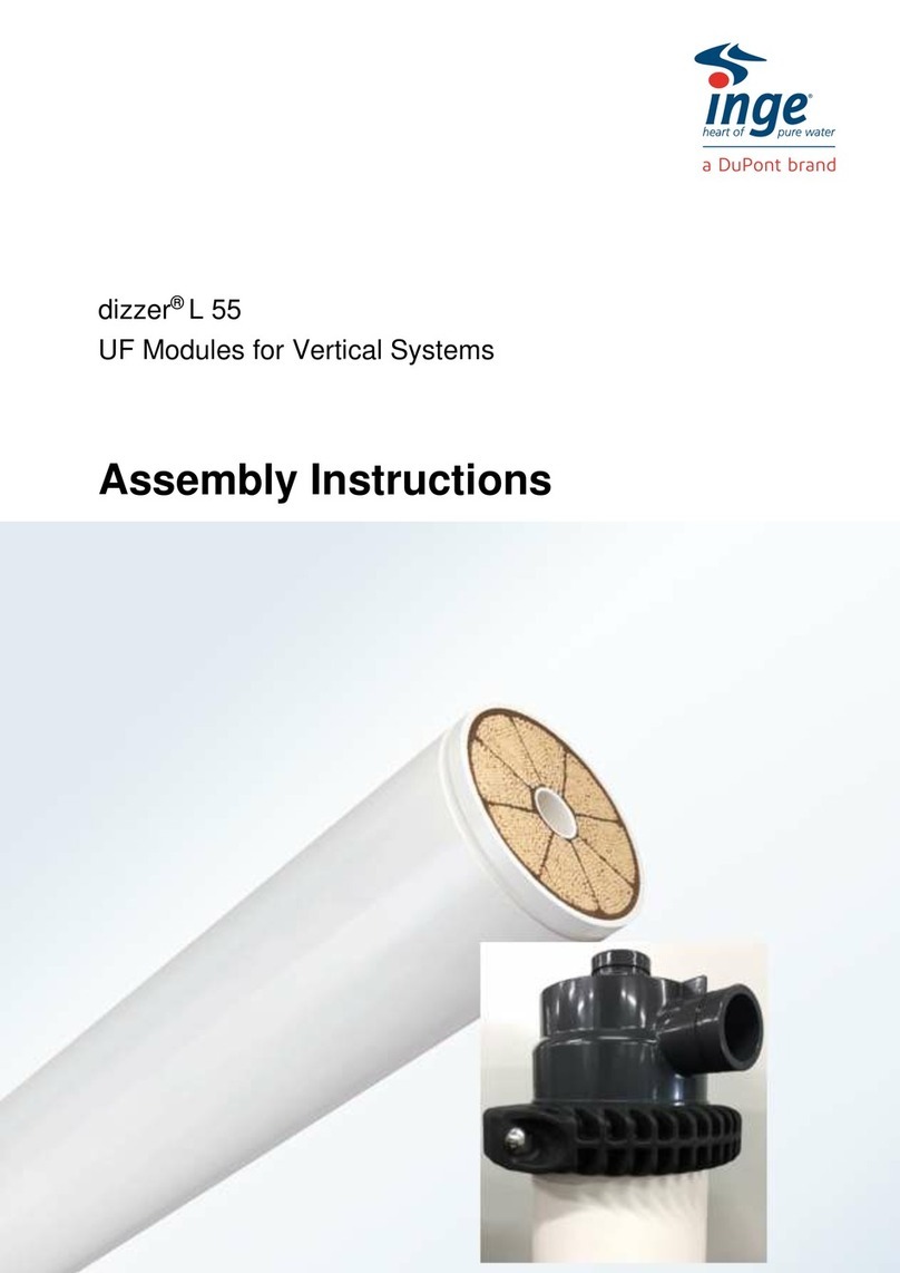
Dupont IntegraTec P Series User manual

Water Solutions
DuPont™ IntegraTec™ P Series
PVDF-UF Out-In
XP 55 UXA Open Platform Modules
Assembly Manual
Version 1
September 2023
NOTICE: The information provided in this literature is given in good faith for informational purposes only. DuPont assumes
no obligation or liability for the information presented herein. NO WARRANTIES ARE GIVEN; ALL IMPLIED WARRANTIES OF
MERCHANTABILITY OR FITNESS FOR A PARTICULAR PURPOSE ARE EXPRESSLY EXCLUDED

Legal Notice
Page 2 of 13 Form No. 45-D04608-en, Rev 0
September 2023
Table of Contents
1. Legal Notice............................................................................................................................................................. 3
1.1 Product..............................................................................................................................................................................................................................3
1.2 Change Policy................................................................................................................................................................................................................3
2. About these Instructions..........................................................................................................................................4
2.1 Objective of these Instructions........................................................................................................................................................................... 4
3. Tools and Equipment ...............................................................................................................................................5
4. End Cap Assembly....................................................................................................................................................6
4.1 Lift up module.............................................................................................................................................................................................................. 6
4.2 Place liquid holder..................................................................................................................................................................................................... 6
4.3 Discharge storage solution ................................................................................................................................................................................... 6
4.4 Prepare End Caps ........................................................................................................................................................................................................7
4.5 Install Filtrate End Cap ..............................................................................................................................................................................................7
4.6 Install Feed End Cap ................................................................................................................................................................................................. 8
5. Install Module to Skid ..............................................................................................................................................9
5.1 Pre-install feed and filtrate connector to the opening of skid..........................................................................................................9
5.2 Connect Module to Skid ..........................................................................................................................................................................................9
5.3 Fix module to skid properly to prevent falling off ...................................................................................................................................9
5.4 Connect Feed Filtrate and Concentrate Openings ...................................................................................................................................9
5.5 Repeat Installation for remained modules...................................................................................................................................................9
List of Figures
Figure 1 Tools and Equipment ........................................................................................................................................................................................................5
Figure 1 Liquid collection basin beneath the module ends......................................................................................................................................... 6
Figure 3 Empty storage solution...................................................................................................................................................................................................7
Figure 4 Description of End Cap Accessory............................................................................................................................................................................7
Figure 5.
Filtrate Clamp Orientation ......................................................................................................................................................................................... 8
Figure 6. Feed Clamp Orientation .............................................................................................................................................................................................. 8
Figure 7. DuPont™ IntegraTec™ XP 55 UXA - End Cap Assembly Type I Installation Drawing.............................................................. 10
Figure 8. DuPont™ IntegraTec™ XP 55 UXA - End Cap Assembly Type II Installation Drawing..............................................................11
Figure 9. DuPont™ IntegraTec™ XP 55 UXA - End Cap Assembly Type III Installation Drawing............................................................12

Legal Notice
Page 3 of 13 Form No. 45-D04608-en, Rev 0
September 2023
1. Legal Notice
1.1 Product
This manual applies to DuPont™ IntegraTec™ PVDF-UF Out-In P Series Modules for Open Platforms, parts and components
for installation, assembly and disassembly.
Duplication and archiving in any form whatsoever – including of excerpts – is only permitted with the written consent of
the manufacturer.
All brand and company names in these process and design guidelines are registered trademarks of the corresponding
companies.
1.2 Change Policy
The manufacturer reserves the right to change this manual or any part thereof at any time in the interest of continuous
product improvement.
The company/party responsible for process and design of the system described in this manual should obtain the current
DuPont™ IntegraTec™ PVDF-UF Out-In P Series XP 55 UXA Modules for Open Platforms Assembly Manual at regular
intervals:
•Download at: https://www.dupont.com/brands/integratec-ultrafiltration.html
IntegraTec
™

About these Instructions
Page 4 of 13 Form No. 45-D04608-en, Rev 0
September 2023
2. About these Instructions
NOTE
READ THE INSTRUCTIONS!
Read these instructions completely before assembling and disassembling
the equipment. The information contained herein will help you perform
the work properly.
It is important to follow the safety instructions to prevent injury and
property damage.
Keep these instructions in a readily accessible place close to the DuPont™
IntegraTec™ PVDF-UF Out-In P Series XP 55 UXA Modules. Include these
instructions if you pass the IntegraPac™ on to a third-party.
2.1 Objective of these Instructions
•These instructions will enable you to properly, safely and quickly assemble and disassemble a
DuPont™ IntegraTec™ PVDF-UF Out-In P Series XP 55 UXA Modules.
•These instructions contain additional important information on maintaining the DuPont™ IntegraTec™ PVDF-
UF Out-In P Series XP 55 UXA Modules.
•The order in which these instructions are presented is designed for optimal learning, enabling you to work
your way into the subject matter step by step.
Warranty Policy
NOTE
ADHERENCE TO ALL INSTRUCTIONS!
Full and proper compliance with the Assembly Instructions is a
prerequisite for making a claim under the warranty.
Any translations of this document into languages other than English
provided to you by DuPont are not official translations and are intended
solely as a convenience for non-English reading recipients. The only
DuPont-approved and valid version of this document is the most current
English version provided by DuPont at the time of sale.
In the event of making a warranty claim, the customer agrees to
automatically provide DuPont™ with a complete set of documentation.
Please contact DuPont™ if you wish to deviate from any of the guidelines
or specifications provided in this document and request written approval
in advance. Otherwise, you risk invalidating any warranty claims that you
may make in the future.

Tools and Equipment
Page 5 of 13 Form No. 45-D04608-en, Rev 0
September 2023
3. Tools and Equipment
Prepare following tools and equipment before module assembly and installation, Figure 1.
Safety Goggle;
Glove;
Latex glove;
Scissors;
Screw driver
Liquid collection basin;
Shelf or platform for module placing;
Figure 1 Tools and Equipment

End Cap Assembly
Page 6 of 13 Form No. 45-D04608-en, Rev 0
September 2023
4. End Cap Assembly
4.1 Lift up module
Open cardboard box, lift module out of it and place on the platform or shelf, keep two ends of module above the
ground.
4.2 Place liquid holder
Place two liquid collection basin beneath the module ends, Figure 2.
Figure 2 Liquid collection basin beneath the module ends
Cautions:
Each non-anti-freezing module (GMID 12091655,12091656) contains 4 L storage solution, the major ingredients
of the liquid are 1.3% Sodium Metabisulfite, 2.5% Sodium Citric, with the pH at 4~5, CODCr at around
26,000mg/L. Each anti-freezing module (GMID 12091659, 12091658) contains 23L storage solution, the major
ingredients of the liquid are 1.2% Sodium Metabisulfite, 2.5% Sodium Citric and 60% glycerin, with the pH at 4~5,
CODCr at around 730,000mg/L. Please choose liquid collection basin with proper volume.
Please dispose the storage solution in compliance with local regulation.
4.3 Discharge storage solution
Dismount module shipping plugs (6, please refer to attachments for all the parts name and number mentioned in this
document) at two ends, and the concentrate plug (10). Remove X-rings (7) and concentrate seal (9), keep them clean and
restore for use. Gradually lift up module at filtrate end, keep the module at the inclined angel (<30 degree) and empty the
storage solution from feed opening.
Cautions:
Always keep the X-rings and seals clean, prevent them from dust and particle contamination.

End Cap Assembly
Page 7 of 13 Form No. 45-D04608-en, Rev 0
September 2023
Wear safety goggle and latex glove before opening end caps, be careful of the liquid when dismounting the
blind plates and concentrate plug. If storage solution splash to the operators’ hands and skid, please rinse with
water immediately.
Do not lift module too much to sliding it off the shelf or platform.
Figure 3 Empty storage solution
4.4 Prepare End Caps
Take out two end caps from the end cap package.
The XP 55 UXA module is accommodated with three different end caps accessory, please confirm the actual end cap type
used at site and refer to the following assembly procedures accordingly.
End Cap Assembly Type I End Cap Assembly Type II End Cap Assembly Type III
GMID 12099259 12099258 12099245
Figure 4 Description of End Cap Accessory
4.5 Install Filtrate End Cap
Install X-ring (7) to the filtrate end, then assemble the top end cap A or B(whichever appropriate) to it, install head clamp
pairs (4) , fasten spacer pairs (5), nuts M10 (2), Double-Threaded Bolts (3) , screw nuts tightly at the torque of 30N•m, Figure 5.

End Cap Assembly
Page 8 of 13 Form No. 45-D04608-en, Rev 0
September 2023
Figure 5.
Filtrate Clamp Orientation
Cautions:
Do not mistaken the filtrate end and ensure X-ring installed in position.
Request the latest exploded drawing from your DuPont contact:
•DuPont™ IntegraTec™ XP 55 UXA - End Cap Assembly Type I Technical Drawing (Form No 45-D02586-en)
•DuPont™ IntegraTec™ XP 55 UXA - End Cap Assembly Type II Technical Drawing (Form No 45-D02587-en)
•DuPont™ IntegraTec™ XP 55 UXA - End Cap Assembly Type III Technical Drawing (Form No 45-D02588-en)
4.6 Install Feed End Cap
Install X-ring (7) to the feed end, then assemble the bottom end cap A or B(whichever appropriate) to it, install head clamp
pairs (4) , fasten spacer pairs (5), nuts M10 (2), Double-Threaded Bolts (3) , screw nuts tightly at the torque of 30N•m, refer to
Feed Clamp Orientation.
Figure 6. Feed Clamp Orientation
Cautions:
Do not mistaken the filtrate end and ensure X-ring installed in position.
Request the latest exploded drawing from your DuPont contact:
•DuPont™ IntegraTec™ XP 55 UXA - End Cap Assembly Type I Technical Drawing (Form No 45-D02586-en)
•DuPont™ IntegraTec™ XP 55 UXA - End Cap Assembly Type II Technical Drawing (Form No 45-D02587-en)
•DuPont™ IntegraTec™ XP 55 UXA - End Cap Assembly Type III Technical Drawing (Form No 45-D02588-en)

Install Module to Skid
Page 9 of 13 Form No. 45-D04608-en, Rev 0
September 2023
5. Install Module to Skid
5.1 Pre-install feed and filtrate connector to the opening of skid
End cap assembly I Module: refer to Figure 7. DuPont™ IntegraTec™ XP 55 UXA - End Cap Assembly Type I Installation
Drawing, install two compressions coupling 2"(13) to the feed and filtrate opening of skid.
End cap assembly II Module: refer to Figure 8. DuPont™ IntegraTec™ XP 55 UXA - End Cap Assembly Type II Installation
Drawing, install silicon gasket (17, please refer to attachment 2) and compression coupling 2"(13) to feed and filtrate opening
of skid respectively.
End cap assembly III Module: refer to Figure 9. DuPont™ IntegraTec™ XP 55 UXA - End Cap Assembly Type III Installation
Drawing, install gasket of Victaulic Coupling 2" (17, please refer to attachment 3) and compression coupling 2"(13) to feed
and filtrate opening of skid respectively.
5.2 Connect Module to Skid
Lift up module to the skid, align module feed opening (Opening 3) to feed opening of skid, then align module concentrate
opening (opening 2) to concentrate opening of skid. If flexible tube is employed for the skid concentrate line, then only
need to move module concentrate opening to the same orientation of the flexible tube.
5.3 Fix module to skid properly to prevent falling off
Cautions:
For End Cap Assembly I module, bind module body with the closest skid frame properly.
5.4 Connect Feed Filtrate and Concentrate Openings
End cap assembly I Module:refer to Figure 7. DuPont™ IntegraTec™ XP 55 UXA - End Cap Assembly Type I Installation
Drawing. Move up compression coupling 2"(13) to the feed cap of the module (Opening 3) and tighten the coupling properly.
Move down compression coupling 2"(13) to the filtrate cap of the module (Opening 1) and tighten the coupling properly.
Install concentrate seal (9) to the concentrate opening of module (Opening 2), connect module concentrate opening and
skid concentrate opening and tighten the concentrate nut (11) properly.
End cap assembly II Module: refer to Figure 8. DuPont™ IntegraTec™ XP 55 UXA - End Cap Assembly Type II Installation
Drawing. Tighten Silicon Clamp (18, please refer to attachment 2) manually. Move down compression coupling 2"(13) to the
filtrate cap of the module (Opening 1) and tighten the coupling properly. Install concentrate seal (9) to the concentrate
opening of module (Opening 2), connect module concentrate opening and skid concentrate opening and tighten the
concentrate nut (11) properly.
End cap assembly III Module: refer to Figure 9. DuPont™ IntegraTec™ XP 55 UXA - End Cap Assembly Type III Installation
Drawing. Move up gasket of coupling 2"(17, please refer to attachment 3) to the feed cap of the module (Opening 3) and
tighten the coupling properly.
Move down compression coupling 2"(13) to the filtrate cap of the module (Opening 1) and tighten the coupling properly.
Install concentrate seal (9) to the concentrate opening of module (Opening 2), connect module concentrate opening and
skid concentrate opening and tighten the concentrate nut (11) properly.
5.5 Repeat Installation for remained modules
Repeat 2.1 to 3.4 until all modules be installed and fixed, rinse UF system with the guidance of the Ultrafiltration user manual.

Install Module to Skid
Page 10 of 13 Form No. 45-D04608-en, Rev 0
September 2023
Figure 7. DuPont™ IntegraTec™ XP 55 UXA - End Cap Assembly Type I Installation Drawing

Install Module to Skid
Page 11 of 13 Form No. 45-D04608-en, Rev 0
September 2023
Figure 8. DuPont™ IntegraTec™ XP 55 UXA - End Cap Assembly Type II Installation Drawing

Install Module to Skid
Page 12 of 13 Form No. 45-D04608-en, Rev 0
September 2023
Figure 9. DuPont™ IntegraTec™ XP 55 UXA - End Cap Assembly Type III Installation Drawing

Have a question? Contact us at:
www.dupont.com/water/contact-us
All information set forth herein is for informational purposes only. This information is general information and may
differ from that based on actual conditions. Customer is responsible for determining whether products and the
information in this document are appropriate for Customer’s use and for ensuring that Customer’s workplace and
disposal practices are in compliance with applicable laws and other government enactments. The product shown in
this literature may not be available for sale and/or available in all geographies where DuPont is represented. The
claims made may not have been approved for use in all countries. Please note that physical properties may vary
depending on certain conditions and while operating conditions stated in this document are intended to lengthen
product lifespan and/or improve product performance, it will ultimately depend on actual circumstances and is in no
event a guarantee of achieving any specific results. DUPONT ASSUMES NO OBLIGATION OR LIABILITY FOR THE
INFORMATION IN THIS DOCUMENT. References to “DuPont” or the “Company” mean the DuPont legal entity selling
the products to Customer unless otherwise expressly noted. NO WARRANTIES ARE GIVEN; ALL IMPLIED WARRANTIES
OF MERCHANTABILITY OR FITNESS FOR A PARTICULAR PURPOSE ARE EXPRESSLY EXCLUDED. No freedom from
infringement of any patent or trademark owned by DuPont or others is to be inferred.
DuPont™, the DuPont Oval Logo, and all trademarks and service marks denoted with ™, SM or ® are owned by affiliates
of DuPont de Nemours, Inc. unless otherwise noted. © 2023 DuPont. All right reserved
Page 13 of 13 Form No. 45-D02507-en, Rev 0
September 2023
Other manuals for IntegraTec P Series
2
This manual suits for next models
1
Table of contents
Other Dupont Water Filtration System manuals
Popular Water Filtration System manuals by other brands

Pentair
Pentair EZ-RO 200/2G-BL Installation & operation guide

SpectraPure
SpectraPure PSP-600 Operation and maintenance manual

GE
GE Profile PNRQ15FBL Owner's manual and installation

Duo-Therm
Duo-Therm GENESIS 3308120.XXX Installation and operating instructions

Cuisinart
Cuisinart Clean Water WCH-850 Instruction booklet

ROSEDALE
ROSEDALE M-8 Installation, operation & maintenance manual