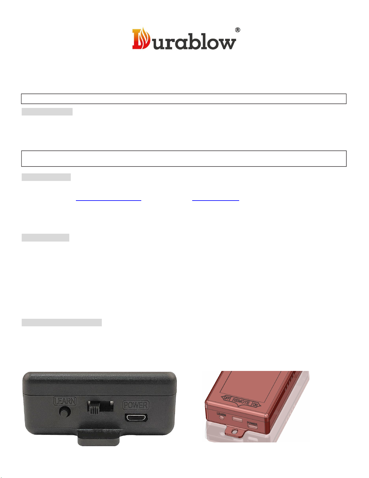
Durablow TR2001 Manual

1
INSTALLATION & OPERATING INSTRUCTIONS (2022/09/06)
( Model: TR2001; Transmitter: T1001 + Receiver: RR11)
IF YOU CAN NOT READ OR UNDERSTAND THESE INSTALLATION INSTRUCTIONS, DO NOT ATTEMPT TO INSTALL OR OPERATE.
INTRODUCTION
This Durablow remote control system is to provide a safe and reliable remote control system for gas heating appliances,
such as fireplace, stove, fire-pit. This remote turns ON or OFF the gas valve. The system operates on radio frequencies
(RF) within a 20-foot range using non-directional signals.
Read ALL sections and original manufacturer manual for safety installation before any action. These safety features shut
down the system and appliance, such as fireplace when a potentially unsafe condition exists, such as high-heat.
PACKING LIST:
Please check and make sure all parts are in good condition before installation. Any questions, please do NOT return to
dealer, but email us (info@payandpack.com) and contact us on PayandPack.com immediately, we will provide solutions
shortly. Thank you.
Includings: 1. Remote transmitter T1001; 2. Remote control receiver box RR11 with two signal wires; 3. USB
power cord + adapter; 4. Installation Instructions.
TRANSMITTER
The transmitter requires two AAA-size 1.5V batteries (excluded). New (fully charged) batteries are preferred for proper
functionality of the system. Insert batteries into the transmitter battery compartment on the back, positioning the (+) and (-)
ends of the batteries as indicated on the casing. (Fig. 1)
The LED signal light on transmitter should illuminate when either the ON or OFF button is pressed. If the signal light does
not illuminate, check the position of the transmitter’s battery, and if it is fully charged. Or go to “LEARN” section.
ON button: Turn ON controlled device, such as Millivolt gas valve or electronic module.
OFF button: Turn OFF controlled device.
REMOTE RECEIVER BOX
Power Source: Input 100-240VAC (universal voltage). USB power cord + adapter with US 2-prong plug.
The remote control receiver box equips with two 18 gauge signal wires (Temperature resistance 200℃Max.)
The remote receiver box has a 3-position slide switch (ON / REMOTE / OFF) & a LEARN button on the side panel
(Fig. 1 & 2).
Fig. 1 (side view)
Fig. 2 (top view)

2
(Fig. 2)
ON mode: Slide the switch to the ON position, the system will remain ON all the time no matter the power cord is
connected or not. Only remote transmitter is disabled.
REMOTE mode: Slide the switch to the REMOTE position (middle), the system will ONLY operate with receiving
commands from the remote transmitter.
OFF mode: Slide the switch to the OFF position, the system will remain OFF all the time. Remote transmitter and
Receiver box are both disabled.
★
NOTE: The OFF mode is strongly recommended if house is unattended for a long time. For safety, placing the slide
switch in the OFF position also functions as a safety “LOCK-OUT” by both turning the system off and disable the remote
receiver.
LEARN / PAIR TRANSMITTER WITH RECEIVER BOX
Pair the transmitter with receiver first if they do NOT communicate. To have the receiver box to accept the transmitter’s
signal (code), please follow the steps below:
1. Unplug the receiver box from power source before LEARN process. Then, plug-in again.
2. Slide the switch to “REMOTE”. Install the RF antenna onto receiver box.
3. Press the “LEARN” button on receiver (Fig. 1) for 1 second, then the receiver box will sounds of quick BEEP X 2 (♫, ♫).
4. Press the ON button on transmitter. The receiver box will sounds of quick BEEP X 3 (♫ , ♫ , ♫ ) to indicate that the
transmitter’s code has been captured by the receiver. It means the LEARN process is completed.
If you fail the LEARNING of matching the security code, please wait 2 minutes before another try. The interval allows the
microprocessor in the receiver box to reset itself and available for accepting new code. Please try more times.
Any questions, please email us. (info@payandpack.com)
W
ARNING & REMINDER
This system MUST be installed exactly as complied with these instructions. Read all instructions before
installation, and follow them during installation carefully.
Any modifications of Durablow remote control system, or parts, or components are PROHIBITED. They will void
the warranty, and may cause a fire hazard result in human casualties and property damages.
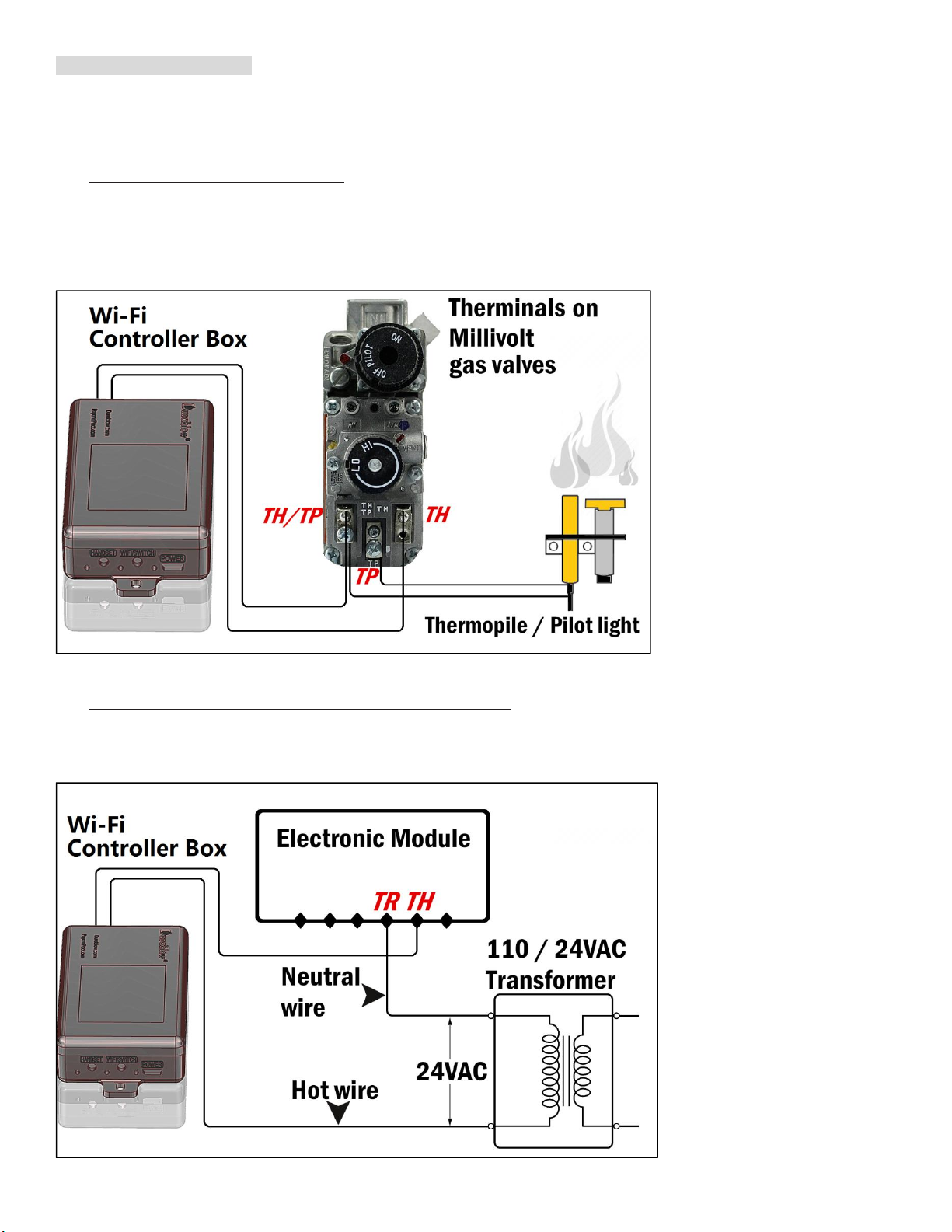
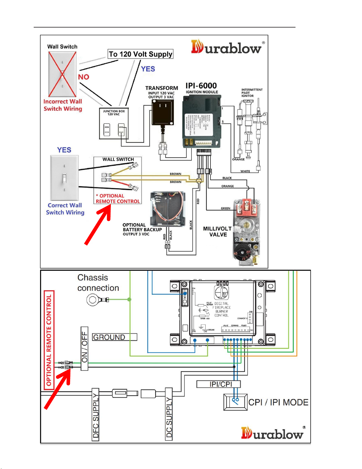
Do NOT connect any gas valve or electronic module directly to power source.
Read gas appliance manufacturer’s instructions and wiring schematics completely for proper placement of all
wires. All electronic modules are to be wired to manufacturer’s specifications.
All wiring diagrams in these instructions are for illustration purpose ONLY. Follow instructions from manufacturers of
gas valve and electronic module for correct wiring & installation procedures. Improper installation of electric
components can cause damage to electronic module, gas valve and remote receiver.
PRE - INSTALLATION
Decide where to install the receiver box before proceeding. Less metallic shielding / blocking, better signal strength.
The remote receiver box can be placed on the fireplace, under the fireplace, behind the control panel or louvers....etc.
Keep away from high-heat of exceeding 130°F. Additional protection is required for no exposure to the heat. Make sure
the receiver box’s slide switch is in the OFF position before installation.

3
WIRING INSTRUCTIONS
ONLY qualified electrician / gas technician with the knowledge of gas appliances and gas valves that are permitted to
install the remote control system. Incorrect wiring installation will damage the gas valve, electronic module of gas
appliance and also the remote receiver.
a. WIRING MILLIVOLT VALVE (Fig. 3)
Connect the two 18 gauge stranded or solid wires of the Remote receiver box to the Millivolt gas valve at the TH & TH/TP
terminals on the terminal block. It does not matter which wire go to which terminal.
The remote receiver box‘s operation is similar to a thermostat that also turn the gas valve ON and OFF based on the input
signals from TH & TH/TP terminals. Transmitter sends signals to receiver box, and receiver box pass the signals to
Millivolt valve to function the ON and OFF of fire / heater.
Fig. 3
b. WIRING ELECTRONIC SPARK IGNITION MODULE (Fig. 4)
Connect a 24VAC transformer in series to the TR (transformer) terminal on the ELECTRONIC MODULE. Connect the hot
wire from the 24VAC transformer to either of the wire terminals on the remote receiver box. Connect another wire between
receiver wire terminal and the TH (thermostat) terminal on the ELECTRONIC MODULE.
Fig. 4

4
c. WIRING DEXEN (Fig. 5) or S.I.T (Fig. 6) ELECTRONIC IPI PILOT IGNITION CONTROL MODULE
Find the “OPTIONAL REMOTE CONTROL” wires to connect Durablow remote controls.
Fig. 5
Fig. 6

5
TROUBLESHOOTING
For all Durablow fireplace remote control kits
OBSERVED PROBLEM
POSSIBLE
CAUSE
REMEDY
Fireplace fire shuts off
in use.
(If equips ODS - Oxygen
Depletion Sensing)
1. No enough fresh air in room, the ODS
pilot shuts off the entire system.
2. ODS/pilot is partially clogged.
1. Open window and/or door for
ventilation.
2. Clean ODS/pilot.
Fireplace fire shuts off
in use.
1. Timer is up or schedule is triggered.
2. Receiver box is overheated.
3. *Set Temperature is reached. (if use a
Thermostat remote control model)
4. Power outage or battery low.
1. Check Timer or Schedule settings.
2. Relocate receiver away from heat.
3. *Check thermostat setting.
4. Check power source, power cord or
replace batteries.
Main fire does not light
after pilot is lit.
1. Inlet gas pressure is too low.
2. Thermopile leads disconnected or
improperly connected.
3. Thermopile damaged.
4. Remote control receiver box wires
disconnected or improperly connected.
5. Pilot fire is OFF accidentally or clogged.
1. Contact local nature gas company.
2. Reconnect thermopile leads.
3. Replace thermopile.
4. Reconnect the wires to TH, TH/TP
terminals of Millivolt valve properly.
5. Ignite pilot fire again, or clean pilot.
No voltage output from
Durablow remote
control receiver box
when control is ON.
The remote control receiver box does NOT
output a micro-volt voltage by itself (for no
danger of gas leakage). It passes or no-
pass the voltage that is generated by
thermopile (heated by pilot fire).
1. Turn ON the pilot fire.
2. Reconnect thermopile leads.
3. Replace thermopile.
4. Switch the receiver box to
“REMOTE” mode.
5. Allow more time to have thermopile
heated to generate voltage.
Durablow remote
control does not
function.
1. No battery or battery is low.
2. Weak signal. Receiver is obstructed or
covered by metal objects / housing.
3. Out of use distance.
4. Weak Wi-Fi (smart home remote only)
5. Defective device.
1. Replace batteries in transmitter and
receiver.
2. Relocate receiver.
3. Relocate receiver and transmitter.
4. Relocate receiver or Wi-Fi router.
5. Contact seller for replacement.
Fireplace fire is ON and
OFF too often or too
slow. (Thermostat remote
control model only)
1. Temperature “SWING” setting is too
small or too big.
1. Find “SWING” setting on transmitter
handset, or Smart Life APP (Smart
Home remote control models),
and reselect appropriate Swing levels:
2°F(1°C), 4°F(2°C), 6°F(3°C)

6
Pilot fire can NOT be
ignited by Durablow
remote control.
Durablow remote control is not a ignitor, it
acts like a main gas fire ON/OFF switch.
Not used for igniting pilot fire or main fire.
1. Ignitor is damaged or battery low.
2. Millivolt valve is not at INGITE mode.
3. Fireplace IPI control is not working.
1. Ignite pilot fire by built-in fireplace
spark ignitor, or manual torch lighter.
2. Turn/press knob on Millivolt valve to
release gas for pilot fire.
3. Contact original fireplace maker.
Questions? Please email us info@payandpack.com or visit PayandPack.com or Durablow.com
WARRANTY & LEGAL DISCLAIMER
Warranty:
Durablow warrants this remote control system for a 1-YEAR LIMITED WARRANTY of the original purchaser / owner of
this system. This warranty is not transferable to another person. it is for the original purchaser of the product. Durablow
warrants any parts failed because of defective workmanship in production or materials from the original date of purchase.
Durablow will repair or replace the defective parts at Durablow’s decision.
Replacement parts will be available at NO charges and free-shipping to users during this warranty. If Durablow does not
have the parts for a certain model, then a replacement system will be provided.
The Owner must provide a bill of sale, order ID or payment record which should be kept to verify purchase date and
establish warranty period.
This warranty does not cover claims. Damage to the system caused by accident, misuse, abuse, or installation error, no
matter implemented by a contractor, third party Service Company, or owner, is not covered by this warranty. Any
modifications of the system will void this warranty.
Photos and simple questions may be required for further product investigation & improvement. Durablow & PayandPack
will reserve the right to physically inspect the product for defects, by authorized representatives.
Legal disclaimer:
Due to different using circumstance, user should take specific advice from qualified technician or professional people
before undertaking any action following information included in these instructions above.
All users who ignore this disclaimer, misuse, abuse, or install the system improperly are at their own risk.

7
FCC / ID
FCC STATEMENT
This device complies with Part 15 of the FCC rules. Operation is subject to the following two conditions: 1) this device may
not cause harmful interference, and 2) this device must accept any interference received, including interference that may
cause undesired operation.
Changes or modifications not expressly approved by the party responsible for compliance could void your authority to
operate the equipment.
NOTE: This equipment has been tested and found to comply with the limits for a Class B digital device, pursuant to Part
15 of the FCC Rules. These limits are designed to provide reasonable protection against harmful interference in a
residential installation.
This equipment generates uses and can radiate radio frequency energy and, if not installed and used in accordance with
the instructions, may cause harmful interference to radio communications. However, there is no guarantee that
interference will not occur in a particular installation. If this equipment does cause harmful interference to radio or
television reception, which can be determined by turning the equipment off and on, the user is encouraged to try to correct
the interference by one or more of the following measures:
Reorient or relocate the receiving antenna.
Increase the separation between the equipment and receiver.
Connect the equipment into an outlet on a circuit different from that to which the receiver is connected.
Consult the dealer or an experienced radio/TV technician for help.
FCC ID STATEMENT
This device complies with Industry Canada licence-exempt RSS standard(s). Operation is subject to the following two
conditions: (1) this device may not cause interference, and (2) this device must accept any interference, including
interference that may cause undesired operation of the device.
Le présent appareil est conforme aux CNR d'Industrie Canada applicables aux appareils radio exempts de licence.
L'exploitation est autorisée aux deux conditions suivantes : (1) l'appareil ne doit pas produire de brouillage, et (2)
l'utilisateur de l'appareil doit accepter tout brouillage radioélectrique subi, même si le brouillage est susceptible d'en
compromettre le fonctionnement.
FCC ID: 2AKOB-TR1003
Table of contents
Other Durablow Remote Control manuals