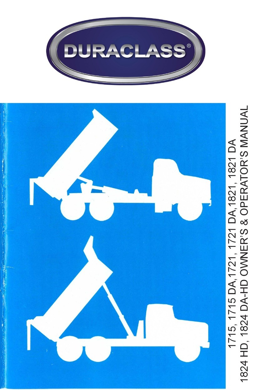
DURACLASS 1715PL User manual

MODEL 1715PL & 1721PL
ARM TYPE
PLATFORM CONVERSION HOISTS
INSTALLATION,OPERATION,MAINTENANCE,& PARTS LISTS MANUAL
IF INCORRECTLY USED, THIS EQUIPMENT CAN CAUSE SEVERE
INJURY. THOSE WHO USE AND MAINTAIN THE EQUIPMENT SHOULD
BE TRAINED IN ITS PROPER USE, WARNED OF ITS DANGERS, AND
SHOULD READ ENTIRE MANUAL BEFORE ATTEMPTING TO SET
UP, OPERATE, ADJUST OR SERVICE THE EQUIPMENT. KEEP THIS
MANUAL FOR FUTURE REFERENCE.
DURACLASS
TED 72050-1182
GENERAL OFFICES: TISHOMINGO, MS
PHONE: CABLE ADDRESS:

IMPORTANT SAFETY NOTICE
Proper service and repair are important to the safe, reliable operation of DuraClass
products. Service procedures recommended by DuraClass are described in this service
manual and are effective for performing service operations. Some of these service op-
erations may require the useof tools or blocking devices specially designed for the pur-
pose. Special tools should be used when and as recommended. It is important to note
that some warnings against the use of specic methods that can damage the product or
render it unsafe are stated in the service manual. It is also important to understand these
warnings are not exhaustive. DuraClas could not possibly know, evaluate and advise the
service trade of all conceivable ways in which service might be done or of the possible
hazardous consequences of each way. Consequently, DuraClass has not undertaken
any such broad evaluations. Accordingly, anyone who uses service procedures or tools
which are not recommended by DuraClass must rst satisfy himself thoroughly that nei-
ther his safety nor the product safety will be jeopardized by the method he selects.
WARRANTY
DuraClass warrants this unit to be free form defects in material and workmanship, under
normal use and service, for a period of ninety (90) days, said period to run from the date
when rst placed into operation.
This warranty is expressly limited to the replacement or repair at its factory in Tishomin-
go, MS. or such other place as DuraClass may designate, of such parts of such products
as shall be returned to it with transportation charges prepaid and which shall appear to
its satisfaction, upon inspection at such factory or other place designated by it, to have
been defective in material or workmanship.
This warranty does not apply to any unit of DuraClass equipment which shall have been
repaired or altered outside of DuraClass so as to affect its stability or which has been
subject to misuse, negligence or accident or which shall have been installed or operated
other than in accordance with the printed instructions of DuraClass.
This warranty does not obligate DuraClass to bear the cost of labor in replacing defec-
tive parts. No other obligation is assumed or authorized to be assumed with respect to
productsof DuraClass other than herein set forth.
DURACLASS DOES NOT ASSUME ANY LIABILITY FOR SECONDARY CHARGES,
EXPENSES FOR ERECTING OR DISCONNECTING, OR ANY OTHER CONSEQUEN-
TIAL LOSSES OR DAMAGES.
"WE MAKE NO OTHER WARRANTY, EXPRESS OR IMPLIED, AND MAKE NO
WARRANTY OF MERCHANTABILITY OR OF FITNESS FOR ANY PARTICULAR
PURPOSE."
DURACLASS
TISHOMINGO,MS.

-3-
INDEX
Page
Important Safety Notice & Warranty........................................................................................................2
Decal Placement. .....................................................................................................................................4
SECTION 1 — GENERAL INFORMATION
1.1 Introduction ................................................................................................................................6
1.2 General Information....................................................................................................................6
1.3 Hoist Capacity .........................................................................................................................6
SECTION 2 — INSTALLATION INSTRUCTIONS
2.1 Hoist & Spacer Pads....................................................................................................................8
2.2 Power Take-Off, Pump & Drive Line ................................................................................8
2.3 Controls.......................................................................................................................................8
2.4 Piping & Filling System..............................................................................................................8
2.5 Remount Body & Body Guides...................................................................................................9
2.6 Venting of System........................................................................................................................9
2.7 Decals...........................................................................................................................................9
SECTION 3 — OPERATION
3.1 General .......................................................................................................................................12
3.2 DenitionofanOperator............................................................................................................12
3.3 Power Take-Off Operation .........................................................................................................12
3.4 Hoist Operating Instructions.......................................................................................................13
3.5 Vehicle Storage...........................................................................................................................13
SECTION 4 — MAINTENANCE
4.1 General .......................................................................................................................................14
4.2 Safety Precautions.......................................................................................................................14
4.3 Suggested Preventive Maintenance Program..............................................................................14
4.4 Lubrication..................................................................................................................................15
4.5 Hydraulic Oil...............................................................................................................................15
4.6 Corrective Maintenance (Trouble Shooting)...............................................................................15
SECTION 5 — REPAIRS
5.1 Cylinder.......................................................................................................................................18
5.2 Pump...........................................................................................................................................18
PARTS INFORMATION
Instructions for Ordering Parts...................................................................................................19
Hydraulic Pump (A219C1411 & A219C1412)..........................................................................20
Hoist Frame, 1715PL (A239C442)............................................................................................22
Hoist Frame, 1721PL (A239C479)............................................................................................23
Hydraulic Cylinder, 1715 & 1715PL (A1C3906)......................................................................24
Hydraulic Cylinder, 1721 & 1721PL (A1C3907)......................................................................25
Body Locking Device (A53C455).............................................................................................26
Lube Chart..................................................................................................................................27
Body Prop Installation................................................................................................................28
Valve Control Safety Lock..........................................................................................................29
Controls Installation (701E3029)................................................................................................31
Mounting Drawing, 1715 (701D3499)........................................................................................32
Mounting Drawing, 1721 (701D35010.......................................................................................33
Mounting Drawing, Body Holddown 1715 & 1721, (701D3512)..............................................34

-4-
DECAL PLACEMENT

-5-
DECAL PLACEMENT
ARM HOIST & BODY INSTALLATION
DECAL PLACEMENT & SERIAL
NUMBER PLATES LOCATION
BEFORE PLACING THE DUMP UNIT INTO OPERATION, THESE DECALS MUST BE PLACED IN
THEIR PROPER POSITION.
CAUTION DECAL #212A1103 IS 3-1/2” X 9”. IT MUST BE PLACED ON CHASSIS FRAME
AS SHOWN - ONE ON EACH SIDE.
WARNING DECAL #212A735 IS 1-7/8” X 4-1/2”. IT MUST BE PLACED ON THE DASH
ABOVE CAUTION DECAL #212A1104 THAT IS 1-7/8” X 4-1/2”.
INSTRUCTION DECAL #212A1166 MUST BE PLACED ON DASH NEXT TO THE CAUTION AND
WARNING DECALS AS SHOWN IN THE SKETCH.
CAUTION DECAL #212A1131 IS 4-3/4” X 5”. IT MUST BE PLACED ON THE DUMP BODY
ABOVE THE SERIAL NUMBER PLATE AS SHOWN IN THE SKETCH.
IF THE INSTALLATION HAS LEVER CONTROLS USE DECALS #212A1164. SELECT THE
DECAL THAT CORRESPONDS TO THE DIRECTION OF TRAVEL FOR PTO LEVER IN AND OUT
AND FOR HOIST CONTROL UP AND DOWN.
IF THE INSTALLATION HAS CABLE CONTROLS, YOU WILL USE #212A1167 DECAL FOR
HOIST CONTROL AND #212A1168 DECAL FOR PTO CONTROL. BASED ON THE CONTROLS
INSTALLATION FOR THIS SPECIFIC HOIST, YOU WILL HAVE TO SELECT AND INSTALL
THE PTO DECAL (212A1168-1 or 212A1168-2) THAT CORRESPONDS TO THE DIRECTION
OF TRAVEL OF THE CABLE CONTROLS FOR THE PTO IN AND OUT.
6
1
2
4
3
5

-6-
SECTION 1 — GENERAL INFORMATION
1.1 INTRODUCTION
This instruction manual contains installation, operation, maintenance, and parts list informa-
tion for DuraClass Model 1715 PL and Model 1721 PL conversion hoists.
1.2 GENERAL INFORMATION
These are twin arm type hoists and are designed for use with wood or steel platform bodies.
The 1715PL hoist is used with bodies from 10' (3.048 m) to 15' (4.572 m) long, and the 1721
PL hoist is used with bodies 11' (3.353 m) to 17' (5.182 m) long. These are for single axle
chassis installations and the dumping angle is 45°.
1.3 HOIST CAPACITY
Lifting capacity depends on the body length and the overhang beyond the rear hinge. The
capacities for each model hoist and the recommended body lengths are charted in Figure 1.

-7-
CHASSIS CAB TO
AXLE
BODY LENGTH CAPACITY - BODY & PAYLOAD
1715PL 1721PL
IN. MM FT. M TONS-U.S. TONS-
METRIC
TONS-U.S. TONS-
METRIC
60 1524 10.0 3.048 16.0 14.5
72 1829 11.0 3.353 13.0 11.8 16.0 14.5
12.0 3.658 16.0 14.5 19.0 17.2
84 2134 12.0 3.658 11.0 10.0 13.5 12.2
12.5 3.810 12.0 10.9 14.5 13.2
13.0 3.962 13.0 11.8 15.5 14.1
13.5 4.115 14.0 12.7 17.0 15.4
102 2591 13.0 3.962 8.5 7.7 10.5 9.5
13.5 4.115 9.0 8.2 11.0 10.0
14.0 4.267 9.5 8.6 11.5 10.4
14.5 4.420 10.5 9.5 12.5 11.3
15.0 4.572 11.0 10.0 13.5 12.2
120 3048 15.0 4.572 9.5 8.6
15.5 4.724 10.0 9.1
16.0 4.877 10.5 9.5
17.0 5.182 11.5 10.4
SECTION 1 - GENERAL INFORMATION
Above capacities are based on mounting body with 3" (76 mm) clearance be-
tween front of body and back of cab, and hinge location 32" (813 mm) behind
centerline of rear axle for 1715PL hoist and 33-1/8" (841 mm) for 1721PL hoist.
Also assumes level loading, with center of gravity at midpoint of body.
FIGURE 1 - HOIST LIFTING CAPACITY
FOR MODEL 1715PL AND
MODEL 1721PL
CONVERSION HOISTS
HOIST LIFTING CAPACITY

-8-
SECTION 2 — INSTALLATION INSTRUCTIONS
Refer to mounting drawing 701D3499 for the 1715PL hoist and 701D3501 for the 1721PL hoist and
perform the following.
REVIEW MANUAL BEFORE STARTING INSTALLATION.
STUDY THE JOB CAREFULLY TO DETERMINE ALL OF THE
HAZARDS PRESENT AND SEE THAT ALL NECESSARY
SAFEGUARDS OR SAFETY DEVICES ARE PROVIDED TO
PROTECT ALL PERSONNEL AND EQUIPMENT INVOLVED.
1.1 HOIST AND SPACER PADS
Remove body from chassis. Cut off end of chassis rails as shown and locate hoist frame square
on chassis and with hinge apron tight against end of chassis. Cut off front en dof hoist frame, if
necesary, to hold 3” (76.20 mm) clearance between frame and back of cab.
Locate spacer pads as shown; drill holes in pads to clear rivets, and weld pads to hoist frame.
Locate hold downs and drill holes in chassis for snug t of bolts.
2.2 POWER TAKE-OFF, PUMP AND DRIVE LINE
Select the correct power take-off to match truck transmission. The PTO output shaft should run at
45 to 65 percent of engine speed. Mount PTO according to manufacturer’s recommendation.
Bolt pump to hoist frame as shown and install drive shaft from PTO to pump. The centerline to
centerline of front and rear 80” (2032 mm). Cut drive shafts to the proper length to have maximum
engagement in universal joints. Hand grease end of drive shaft and slip joint before installing. Max-
imum angle on drive line shafts not to exceed 10°. See Figure 2 for installation recommendations.
2.3 CONTROLS
Lever controls are standard and should be mounted on the oor of the cab convenient to operator.
See control installation drawing.
2.4 PIPING AND FILLING SYSTEM
Connect piping from pump to cylinder as shown. Use a thread sealing compound on all pipe
threads.
Remove piping from pump to cylinder as shown. Use a thread sealing compound on all pipe
threads.
Remove vent plug at top of cylinder and ll with oil (See Section 4.5 for proper oil). Replace plug.
CAUTION
!

-9-
SECTION 2 — INSTALLATION INSTRUCTIONS
2.5 REMOUNT BODY AND BODY GUIDES
Install Z Iongmembers. Cut off front of longmemeber, if necessary, to hold 3” (76.20 mm)
clearance between longmember and back of cab. Mount Iongmembers to outside (as shown),
if possible. If longmember are mounted to inside, hinges must be shimmed so that side move-
ment of long members is restricted to 1/8” (3.04 mm). Install grease ttings in hinges.
Install crosshead shaft through pick up plates of longmembers and upper end of links. Bolt in
place.
Remount body so that it is square on the chassis, has the proper cab clearance and ts
snugly into Z longmembers. If wood longmembers on body, bolt to Z longmembers with 1/ 2”
(12.70 mm) carriage bolts (not furnished). If steel longmembers, bolt to Z longmembers with
1/2” (12.70 mm) capscrews (not furnished), or weld body longmember to Z longmembers.
Locate body guides at a convenient location close to cylinder trunnion. Drill (4) 41/64” (16.25
mm) holes in chassis rail, using holes in body guide as a template. Bolt in place.
2.6 VENTING OF SYSTEM
WHEN ANY WORK IS TO BE DONE ON BODY OR HOIST AND
BODY IS FULLY OR PARTLY RAISED, IT MUST BE BLOCKED
SECURELY SO IT CANNOT FALL. IN ADDITION, DISENGAGE
THE PTO AT SUCH TIME.
READ AND STUDY OPERATION SECTION OF ANUAL BEFORE
PROCEEDING.
Raise body slowly until cylinder is fully extended and block body securely. Remove vent plug from
top of cylinder and rell cylinder if necessary. Raise and lower the body several times until air is
eliminated from the system. Recheck oil, observing Warning precautions. With body raised the
oil level should be 2" (50.80 mm) to 3" (76.20 mm) below the ll hole in the cylinder. Add oil, if
necessary. Replace vent plug.
Keep dirt out of system.
2.7 DECALS
Place WARNING and CAUTION decals on instrument panel in plain view of operator and on
body and hoist. See goldenrod sheet B72952-1275 for placement.
CAUTION
!

-10-
SECTION 2 — INSTALLATION INSTRUCTIONS
FIGURE 2 - DRIVE LINE RECOMMENDATIONS
FIGURE 3 - SCHEMATIC OF HYDRAULIC CIRCUIT

-11-
SECTION 2 — INSTALLATION INSTRUCTIONS
WARNING
DO NOT OPERATE OR SERVICE THIS MACHINE
UNTIL YOU HAVE READ AND UNDERSTAND
THE OPERATION AND MAINTENANCE MANUAL
SUPPLIED WITH THIS EQUIPMENT. MANUALS
CAN ALSO BE OBTAINED FROM A DURACLASS
DISTRIBUTOR.
212A735 DURACLASS, TISHOMINGO,MS.
FIGURE 4 - SCHEMATIC OF VALVE POSITIONS
FIGURE 5 - WARNING DECAL

-12-
SECTION 3 — OPERATION
3.1 GENERAL
Before operating this hoist, see capacity chart (Figure 1) and read warningand caution de-
cals on instrument panel, body, and hoist. See goldenrod sheet B72952-1275 for decals and
placement.
WHEN OPERATING DO NOT STAND IN, MOVE THROUGH,
OR ALLOW ANYONE ELSE TO STAND IN OR MOVE
THROUGH THE AREA THAT YOUR HOIST OPERATES AND
PASSES THROUGH, ORINTO AN AREA THAT AN UPSET
LOAD MIGHT FALL.
3.2 DEFINITION OF AN OPERATOR
An operator as referred to herein is a competent person who has read and un-
derstand the "Operation and Maintenance Manual".
3.3 POWER TAKE-OFF OPERATION
1) Mechanical Transmission
—To encourage PTO, place transmission shift lever in NEUTRAL.
—Set hand brake.
—Depress clutch pedal.
—Shift PTO into gear.
—Release clutch pedal.
Equipment is now ready to operate.
2) Allison Transmission
—To engage PTO, stop the truck and set the hand brake.
—With the Allison transmission in any gear position, engage PTO.
NOTE: If gears do not mesh, it may be necessary to let the truck creep slightly in
in gear while putting a slight pull on the PTO control.
—After PTO is engaged, move transmission shift lever to NEUTRAL.
Equipment is now ready to operate.
—To disengage PTO, move transmission shift lever into any gear position and
shift PTO out of gear.
—Move transmission shift lever to NEUTRAL.
Truck is now ready to move.
CAUTION
!

-13-
SECTION 3 — OPERATION
DISENGAGE PTO WHEN HOIST IS NOT IN USE OR WHEN TRAV-
ELING ON THE HIGHWAY. DO NOT MOVE TRUCK (LOADED OR
UNLOADED) UNLESS THE BODY IS LOWERED AND RESTING ON
TRUCK FRAME.
3.4 HOIST OPERATING INSTRUCTIONS
(For schematic of valve positions, see Figure 4.)
To Raise Body — With PTO engaged (See Section 3.3) and truck engine running at a
speed slightly faster than idle, move valve control in cab to RAISE position (rearward).
To Hold Body — To hold in any position, move valve control in cab to HOLD position. If
body will be held in position any length of time, shift PTO out of gear.
To Lower Body — Disengage PTO (See Section 3.3) and move valve control in cab to
LOWER position (forward).
WHEN TRAVELING ON THE HIGHWAY, THE VALVE CON-
TROL LEVER MUST BE KEPT IN THE HOLD POSITION AT ALL
TIMES, AND THE PTO MUST BE DISENGAGED.
3.5 VEHICLE STORAGE
IN ALL CASES, WHEN TRUCK IS STORED OR NOT IN USE,
THE BODY MUST BE IN THE FULL LOWERED POSITION AND
RESTING ON THE TRUCK CHASSIS OR HOIST FRAME. KEY
SHOULD BE REMOVED FROM IGNITION TO PREVENT TAM-
PERING BY UNAUTHORIZED PERSONNEL.
CAUTION
CAUTION
CAUTION

-14-
SECTION 4 —MAINTENANCE
4.1 GENERAL
Maintenance personnel responsible for the upkeep of this equipment should possess a
basic understanding of the equipment and normal sequence of operation. Refer to Sec-
tions 1 and 3 of this manual.
Maintenance discussed in this section is divided into two parts — Preventive Mainte-
nance and Corrective Maintenance (Trouble Shooting).
Preventive Maintenance consists of those routines which keep the equipment in proper
working condition. Preventive Maintenance is not only desirable, but is necessary, since
routine inspection will ensure continued trouble-free operation of the equipment and pre-
vent, or at least detect at an early stage, mechanical or hydraulic troubles that might
otherwise develop into equipment malfunction.
Corrective Maintenance (Trouble Shooting) is the examination and repair or replacement
of the part or parts of the equipment that resulted in equipment malfunction.
4.2 SAFETY PRECAUTIONS
WHEN ANY REPAIRS OR ADJUSTMENTSARE MADEAND BODY
IS FULLY OR PARTLY RAISED, BODY MUST BE BLOCKED SE-
CURELY SO IT CANNOT FALL.
4.3 SUGGESTED PREVENTIVE MAINTENANCE PROGRAM
Suggested preventive maintenance checks are listed below.
Perform These Checks Monthly
1) Check bolt tightness at shear bolt at rear, hinge pins, both ends of lever arm shaft,
upper and lower link pins, cylinder upper and lower pins, hold downs, PTO, pump,
cab control and drive line bearing. Self locking nuts are used throughout unit, and
any time a replacement is needed, it must be replaced with an equal part.
2) Inspect drive line for possible wear and check set screws for tightness and lock
wire in position.
3) Check oil level in cylinder for correct height. See Section 2.9.
4) Check color of oil for possible contamination. If oil appears thick or dirty, drain sys-
tem and replace. See Section 4.5 for proper type oil.
5) Check for oil leaks in all hydraulic ttings and hoses. Retighten ttings and replace
hoses as necessary.
CAUTION

-15-
SECTION 4 —MAINTENANCE
4.4 LUBRICATION
The hoist should be lubricated at least once a week. Use same grease as recommend-
ed for chassis. Lubrication points are as follows:
1) Rear hinges...................................1 tting each hinge
2) Lever arm......................................2 ttings
3) Link................................................2 ttings each link
4) Cylinder upper end........................1 tting
5) Cylinder lower end........................ 1 tting
6) U-Joint...........................................1 tting each
7) Drive line bearing..........................1 tting
Use oil on control rail ends, cable, cable lines, and link ends. Hand grease spline and
sleeve.
4.5 HYDRAULIC OIL
When adding or replacing oil, use a hydraulic oil that contains antifoamant, rust and
oxidation inhibitors, and an antiwear additive. If a hydraulic oil is not available, use an
API engine oil, designation SE, with an SAE viscosity rating of 10W30.
DO NOT use low viscosity naphtha base motor oil, hydraulic brake uid, or aircraft
hydraulic uid.
We recommend that the oil in the system be changed at least twice a year.
4.6 CORRECTIVE MAINTENANCE (TROUBLE SHOOTING)
The operation of any mechanical or hydraulic system depends on the life span of the
various parts. Some parts should last indenitely; others may not. This section is a
general guide to the causes of possible equipment malfunction.
Safety
Respect the potential danger of the equipment. Refer to Section 4.2 "Safety Precau-
tions" before starting any repair.
Test Equipment
Use high quality test equipment. Any gage range should be well beyond the expected
test value.
Trouble Chart
To aid maintenance personnel in locating and correcting a problem, a trouble chart has
been included.

-16-
SECTION 4 —MAINTENANCE
TROUBLE CHART
Trouble Cause Remedy
1) Failure to raise
load.
1 A) Insufcient oil in system. 1 A) Add oil to cylinder to
proper level.
1 B) Air in system. 1 B) Vent air from system.
1C) Pinched hydraulic hose. 1 C) Locate and relieve
pinching. Relocate or
replace hoses as
required.
1 D) Control linkage parts
worn or missing.
1 D) Check linkage for proper connec-
tions. Replace worn or missing parts
1 E) Pump not running. 1 E) Check U-Joints at PTO and pump
for tightness.
1 F) Control valve not operating. 1 F) Check valve for full throw.
1 G) Defective pump. 1 G) (See below)
Remedy: Check pressure in system observing WARNING (Safety Precautions) rules
in Section 4.2 when any adjustments are made. Disconnect hose from base end
of cylinder (temporarily plug this hole in cylinder so that all the oil is not lost.)
and connect to a 0-3000 psi (20 682 kPa) pressure gage. Run pump at about
300 rpm and read gage. DO NOT run pump this way for more than a few sec
onds at a time. The gage should read at least 1000 psi (6 894 kPa) pressure. If
pressure is below this value, pump may be defective. Replace.
2) Oil foaming 2A) Insufcient oil in system. 2A) With body raised the oil level
should be 2” (50.80 mm) to
3” (76.20 mm) below the
cylinder ll hole.
2B) Suction line hose ttings
loosse, allowing air to enter
system.
2B) Tighten hoses and ttings;
vent air from system.

-17-
SECTION 4 —MAINTENANCE
2) (Cont.) 2C) Oil too heavy. 2C) Install proper oil for
expected temperature.
2D) Pump operated at high
speed in cold weather.
2D) Operate pump at slower
speed.
3) Body raises unsteadily,
jerks or vibrates.
3A) Air in system. 3A) Check suction hoses and
ttings for leaks; re-
tighten loose ttings and
vent cylinders.
4) Body will not stay up. 4A) Control valve not shift
ing completely, valve
spool or housing scored.
Check valve not seating
properly. Cylinder or
piston rings scored,
causing internal leakage.
4A) Adjust linkage for com
plete shifting; replace or
repair valve section of
pump. Replace piston
rings. Reseat check
valve. Return cylinder to
DuraCell distributor for
repair or replacement.

-18-
SECTION 5 —REPAIRS
WHEN ANY REPAIRS OR ADJUSTMENTS ARE MADE AND
BODY IS FULLY OR PARTLY RAISED, BODY MUST BE
BLOCKED SECURELY SO IT CANNOT FALL. IN ADDITION,
DISENGAGE PTO AT SUCH TIME.
5.1 CYLINDER
For any major repair the cylinder should be returned to the DuraClass distributor.
Repairs in the eld should be limited to the replacement of rod packing and piston
rings. To replace packing raise body, observing WARNING rules above, unscrew pack-
ing nut, remove present packing and install new packing set. Dip packing in oil before
installing.
To replace piston rings remove cylinder from chassis. Loosen packing nut unscrew cyl-
inder head and remove this assembly from cylinder. Replace piston rings and replace
assembly. Use a new rubber packing ring around cylinder head when reinstalling.
Keep dirt out of system.
5.2 PUMP
Pump (with integral control valve) should be returned to the DuraClass distributor for
any repairs beyond the replacement of seals and O-rings.
CAUTION
!

-19-
PARTS INFORMATION
TO THE OWNER
If you should need information not given in this manual or require the service of a
trained mechanic, we urge you to use the extensive facilities offered by the autho-
rized DuraClass Distributor in your locality.
INSTRUCTIONS FOR
ORDERING REPLACEMENT PARTS
For ease in ordering of DuraClass parts, a system of part and assembly numbers is
used. It's important these numbers be used wherever and whenever possible.
All parts listed on the drawings, repair parts sheets or exploded views show parts in
their proper relationship. Each individual part is identied by name and part number.
Use the following suggestions and you should have little difculty in getting quick and
efcient parts delivery.
IMPORTANT
1) Give Model, Serial, and Identication numbers found on Identication Plate of the
unit. Be sure numbers are complete and include the prex and sufx, if any.
2) Order by Part Number only — Not by Item Number.
3) Check every part number for accuracy. The part numbers, sometimes are very
similar and can be easily transposed.
4) Be careful to order correct quantity.
5) When ordering an assembly, make sure all the parts you need are included in the
assembly.
6) Common hardware is not listed.
7) Say whether shipment is to be made Express, Parcel Post or Freight. Give Freight
shipping point if different from mailing point.
8) ORDER PARTS FROM YOUR NEAREST DURACLASS DISTRIBUTOR.
DURACLASS
TISHOMINGO, MS.

-20-
TRUCK EQUIPMENT DIVISION
REPLACEMENT PARTS LIST HYDRAULIC
PUMP-VALVE
ASSEMBLY
DURACLASS
A219C1411 & A219C1412 GEAR PUMPS WITH ROLLER BEARINGS
DURACLASS TISHOMINGO, MS
This manual suits for next models
1
Table of contents
Other DURACLASS Chain Hoist manuals
Popular Chain Hoist manuals by other brands

Guldmann
Guldmann GH2 F manual

Protekt
Protekt RUP507 Use and installation manual

J. D. NEUHAUS
J. D. NEUHAUS PROFI 3 Ti Operation manual

R&M
R&M LOADMATE LM05 II Series Installation and maintenance manual

Draper
Draper 26188 instructions

J. D. NEUHAUS
J. D. NEUHAUS PROFI 25 TI Operating and assembly instruction

KITO
KITO HARRINGTON MR2Q Series owner's manual

PROCRAFT
PROCRAFT TP250 manual

Chase Doors
Chase Doors DuraShield Series installation manual

CATU
CATU MO-346-S manual

Gis
Gis LPM Translation of the original instruction manual

Paccar Winch
Paccar Winch BRADEN Gearmatic BG6A Installation maintenance and service manual