DuraTech Industries Haybuster 572 Parts list manual

PO BOx 1940, JamestOwn, nD 58402-1940
MAY 2013 0500145
TM
572
ROUND
BALER
Operating Instructions
and Parts Reference

A Tradition of Innovation Since 1966

572
ROUND
BALER
Operating Instructions
and Parts Reference
TM
DuraTech Industries International Inc. (DuraTech Industries) has made every effort to as-
sure that this manual completely and accurately describes the operation and maintenance of
the 572 Round Baler as of the date of publication. DuraTech Industries reserves the right to
make updates to the machine from time to time. Even in the event of such updates, you should
still nd this manual to be appropriate for the safe operation and maintenance of your unit.
This manual, as well as materials provided by component suppliers to DuraTech Industries
are all considered to be part of the information package. Every operator is required to read
and understand these manuals, and they should be located within easy access for periodic re-
view.
& are registered trademarks of Duratech Industries
International, Inc. Haybuster, 572 Round Baler are trademarks of Duratech Industries Inter-
national, Inc.

A Tradition of Innovation Since 1966

i
572 ROUND BALER OPERATING INSTRUCTIONS
FOREWORD
Foreword
All personnel must read and understand the following sections before operating the
572 Round Baler.
•Foreword and Section 1, important safety information.
•Section 2.1, “Pre-Operation Inspection”.
•Section 3, “Machine operation,” which explains normal operation of the ma-
chine.
Appropriate use of unit
The 572 Round Baler is designed to produce round bales.
Operator protection
As with all machinery, care needs to be taken in order to insure the safety of the op-
erator and those in the surrounding area.
WARNING: The OPERATOR IS RESPONSIBLE for the safety of the oper-
ator and those in the surrounding area. Operators and those observing the oper-
ation of the 572 Round Baler are required to wear head, eye, and ear protection,
No loose clothing is allowed.

ii 572 ROUND BALER OPERATING INSTRUCTIONS
A Tradition of Innovation Since 1966

iii
TABLE OF CONTENTS
572 ROUND BALER OPERATING INSTRUCTIONS
Part 1: Operating Instructions ........................................1
Introduction ................................................................................. 2
Purpose ....................................................................................... 2
Section 1: Safety......................................................................... 4
1.1 Safety-alert symbols ........................................................................................ 4
1.2 Operator - personal equipment...................................................................... 6
1.3 Machine safety labels ...................................................................................... 7
1.4 Shielding......................................................................................................... 10
1.5 Safety review Section .................................................................................... 11
1.6 Towing/road transport .................................................................................. 12
1.7 Fire prevention .............................................................................................. 13
Section 2: Pre-Operating .......................................................... 14
2.1 Pre-Operating Inspection ............................................................................. 14
Section 3: Baler Operation ........................................................ 16
3.1 Normal shutdown procedure........................................................................ 16
3.2 Tractor Setup ................................................................................................. 16
3.2.1 Drawbar Adjustment ....................................................................... 16
3.2.2 Hitching to Tractor .......................................................................... 17
3.2.3 Closed or Open Center Tractor hydraulics...................................... 17
3.2.4 Adjusting Hydraulic Outlets............................................................ 18
3.2.5 Installing Monitor............................................................................ 18
3.2.6 Taillights.......................................................................................... 18
3.3 Baler Setup..................................................................................................... 18
3.3.1 Twine............................................................................................... 18
3.3.2 Twine Box ....................................................................................... 18
3.3.3 Twine Routing ................................................................................. 19
3.3.4 Wheel Nut Torque (lug bolts).......................................................... 21
3.3.5 Tires and rims.................................................................................. 21
3.4 Crop Preparation and Windrow Preparation ............................................ 21
3.5 To avoid plugging the baler .......................................................................... 21
3.6 Unplugging the baler..................................................................................... 21
3.7 Road Transport.............................................................................................. 22
3.7.1 Preparing baler for transport ........................................................... 22
3.8 Unhitching from the tractor ......................................................................... 22
3.9 Storing the 572 Round Baler ........................................................................ 23
3.10 Removing the 572 Round Baler from storage........................................... 23

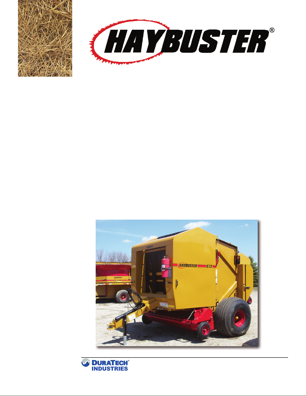
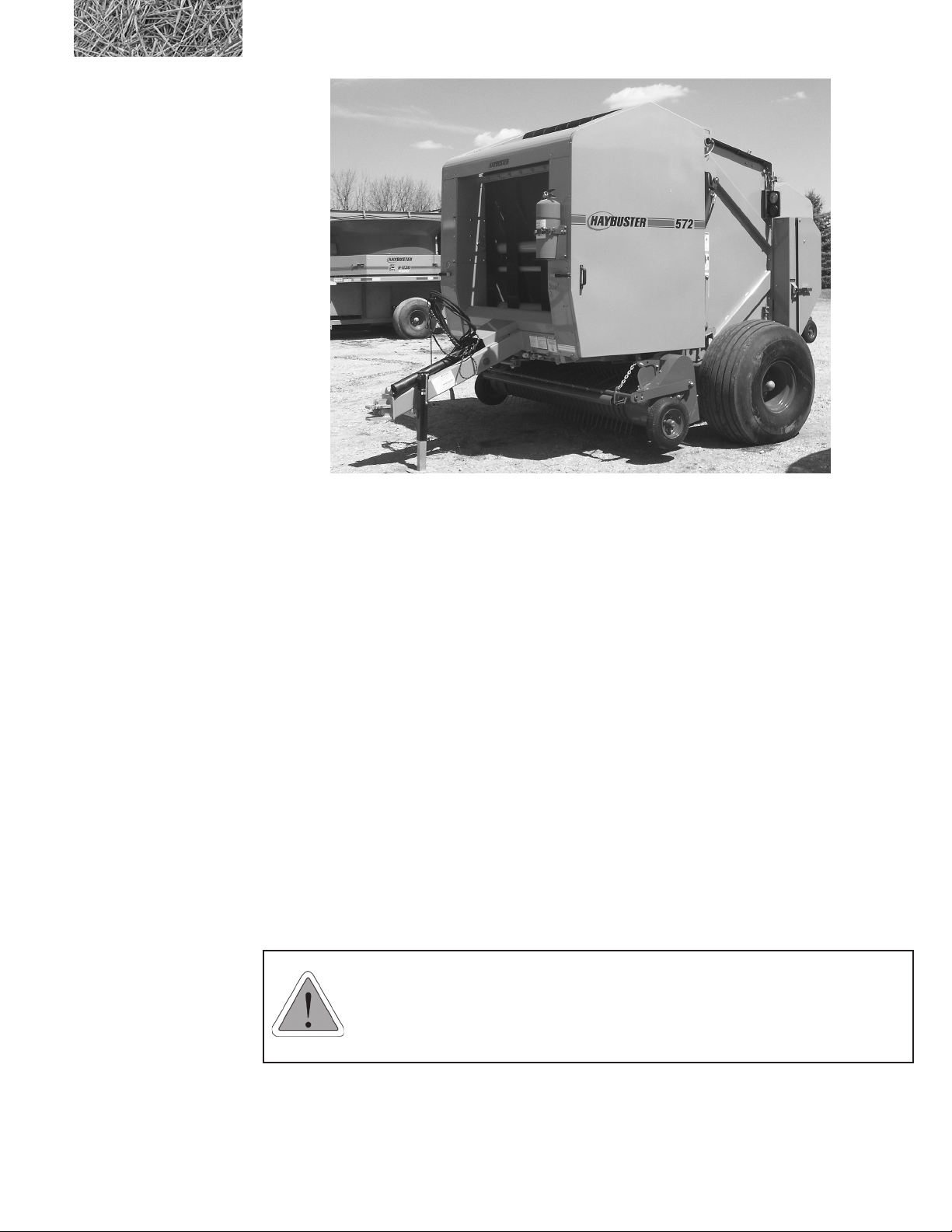
iv 572 ROUND BALER OPERATING INSTRUCTIONS
TABLE OF CONTENTS
Section 4: Baler Adjustment..................................................... 24
4.1 Bale Density Gauge ....................................................................................... 24
4.2 Adjusting Bale Density.................................................................................. 24
4.3 Adjusting twine tension................................................................................. 25
4.4 Adjusting gauge wheels................................................................................. 25
4.5 Gate Locking Procedure............................................................................... 26
4.6 Adjusting Compression Rack....................................................................... 26
4.7 Adjusting Main Drive Chain Tension.......................................................... 27
4.8 Adjusting pickup drive chain ....................................................................... 27
4.9 Adjusting belt tracking ................................................................................. 28
4.10 Adjusting pickup oat................................................................................. 28
4.11 Material Trap Cleanout and Inspection .................................................... 29
4.13 Belt and Lacing Pin Inspection .................................................................. 29
4.12 Secondary Drive Chain Adjustment.......................................................... 29
4.14 Belt Installation and Routing ..................................................................... 30
4.15 Twine Pincher Adjustment ......................................................................... 31
Section 5: Monitor..................................................................... 32
5.1 Monitor Operation ........................................................................................ 32
5.1.1 Bale Monitor Screen ....................................................................... 32
5.1.2 General Layout of controller ........................................................... 32
5.2 Calibration of the 572 Baler – General ....................................................... 33
5.3 Other Diagnosis .............................................................................................. 35
5.4 Menu Screen ................................................................................................. 36
5.4.1 Misc. Setup Screen........................................................................... 36
5.4.2 Twine setup values .......................................................................... 36
5.4.3 Net wrap setup values ..................................................................... 36
5.4.4 Misc Setup Screen........................................................................... 37
5.4.5%FullDenition............................................................................. 37
5.4.6AutoStartDelaydenition.............................................................. 37
5.4.7 Start Wrap/Wrap Reset Functions ................................................... 37
5.4.8 Twine Dispensing Indicators........................................................... 38
5.4.9 Twine Arms Position Indicator........................................................ 38
5.4.10 Auto Dump Feature ....................................................................... 38
5.4.11 Faults Screen ................................................................................. 38
5.4.12 Bale History .................................................................................. 38
5.4.13 Baling sequence ............................................................................ 39
5.4.14 Tying Sequence ............................................................................. 39
Section 6: Lubrication............................................................... 40
6.1 Lubrication .................................................................................................... 40
6.2 Chain Oiler .................................................................................................... 47

v
TABLE OF CONTENTS
572 ROUND BALER OPERATING INSTRUCTIONS
6.3 Gearbox Lubrication..................................................................................... 49
6.4 Hydraulic Cylinders and Valves................................................................... 49
Section 7: Maintenance ............................................................ 50
7.1 General Appearance...................................................................................... 50
7.2 Welding Procedure ........................................................................................ 50
Section 8: Options..................................................................... 51
8.1 Net wrap ......................................................................................................... 51
8.1.1 Loading the net wrap....................................................................... 51
8.1.2 Feeding the net ................................................................................ 53
8.1.3 Cutting the net ................................................................................. 54
8.2 Bale Kicker option......................................................................................... 55
Section 9: Troubleshooting....................................................... 56
Appendix A: WARRANTY........................................................... 59
Appendix B: 572 Haybuster Round Baler Specications......... 60
Part 2: Parts Reference .................................................63
MAIN FRAME ASSEMBLY................................................................................. 64
MAIN FRAME ASSEMBLY DETAILS................................................................ 66
HITCH ................................................................................................................... 68
TENSION ARM ASSEMBLY ............................................................................... 70
ROCK TRAP.......................................................................................................... 72
MAIN DRIVE ........................................................................................................ 74
SECONDARY DRIVE........................................................................................... 78
PICK UP LIFT ASSEMBLY.................................................................................. 80
COMPRESSION RACK ASSEMBLY .................................................................. 82
DUAL TWINE TIE ................................................................................................ 84
BELT GUIDE......................................................................................................... 86
BELT GUIDE - TAILGATE................................................................................... 88
TAILGATE ASSEMBLY ....................................................................................... 90
TAILGATE ASSEMBLY DETAILS ...................................................................... 92
TAILGATE LATCH ASSEMBLY ......................................................................... 94
SHIELD ASSEMBLY ............................................................................................ 96
PICK UP ASSEMBLY ........................................................................................... 98
PICK UP ASSEMBLY DETAILS........................................................................ 100
PICK UP WHEEL AND HUB ASSEMBLY........................................................ 102
DRUM ROLLER ................................................................................................. 104
LONG IDLER ROLLER ASSEMBLY................................................................ 106

vi 572 ROUND BALER OPERATING INSTRUCTIONS
LOWER DRIVE ROLLER ASSEMBLY ............................................................ 108
SHORT IDLER ROLLER ASSEMBLY .............................................................. 110
STARTER ROLLER ASSEMBLY....................................................................... 112
UPPER DRIVE ROLLER ASSEMBLY.............................................................. 114
HYDRAULIC CYLINDER SEALS AND OTHER ITEMS ............................... 116
BALE KICKER (OPTIONAL)............................................................................ 118
NET WRAP (OPTIONAL) .................................................................................. 120
HYDRAULIC VALVE - 4000497 ....................................................................... 123
hydraulic schematic.............................................................................................. 124
HYDRAULICS .................................................................................................... 125
TRACTOR CONNECTIONS .............................................................................. 126
4000497 VALVE .................................................................................................. 127
4000269 VALVE .................................................................................................. 128
4100226 NET WRAP CYLINDER...................................................................... 129
4100283 TWINE CYLINDER............................................................................. 130
4100193 TENSION CYLINDERS ...................................................................... 131
4100241 GATE CYLINDERS ............................................................................. 132
4100252 PICKUP LIFT CYLINDER .................................................................. 133
4100322 KICKER CYLINDER........................................................................... 134
3800381 PRESSURE GAUGE ............................................................................ 135
7501134 OILING SYSTEM ................................................................................ 136
HYDRAULIC PARTS LIST ................................................................................ 137
trailer light harness ............................................................................................... 138
DECALS .............................................................................................................. 140
DECALS LOCATIONS ....................................................................................... 142
572 Round Baler Documentation Comment Form................... 147
FOLDOUTS
TRACTOR WIRING HARNESS ......................................................................FO-1
MACHINE WIRING HARNESS ......................................................................FO-2

1572 ROUND BALER OPERATING INSTRUCTIONS 1
572
ROUND
BALER
Part 1:
Operating Instructions
TM

2572 ROUND BALER OPERATING INSTRUCTIONS
Introduction
The 572 Round Baler is designed to produce round bales.
To avoid possible damage to the machine and risk of injury to the operator, consult with a DuraTech Industries
International, Inc. (DuraTech Industries) representative if you have any questions.
Purpose
The purpose of this owner’s manual is to explain maintenance requirements and routine adjustments for the most
efcient operation of your 572 Round Baler. There is also a trouble shooting section that may help in case of problems
in the eld. Any information not covered in this manual may be obtained from your dealer.
Special Note: When reference is made as to front, rear, left hand, or right hand of this machine, the
reference is always made from standing at the rear end of the machine and looking toward the hitch.
Always use serial number and model number when referring to parts or problems. Please obtain your
serial number and write it below for your future reference.
MODEL: 572 Round Baler SERIAL NO. _______________________
How to use this manual
Manual organization
This manual is organized into the following parts:
• Part 1: Operating Instructions
• Section 1: Safety decals, safety instructions and information
• Section 2: Describes pre-operating procedure.
• Section 3: Describes how to operate the 572 Round Baler.
• Section 4: Describes baler adjustments.
• Section 5: Describes monitor use.
• Section 6 & 7: Describes maintenence of the 572 Round Baler.
• Section 8: Describes the options.
• Part 2: Part’s reference contains diagrams of each assembly, with the part number of each part. A key on
the same or facing page contains a description of the part and the quantity used.

3
572 ROUND BALER OPERATING INSTRUCTIONS
Dealer responsibilities
•Upon delivery of the unit to the customer, it is your responsibility to conduct a training session on the safe
operation of the unit for the primary operator(s). You must also conduct a “walk-around” inspection of all
safety instructional decals on the machine itself. Decals are illustrated in Part 2: Parts Reference.
•Complete and return the Warranty Registration postcard. DuraTech Industries must receive this form
before activating the warranty. Appendix A provides details of the warranty.
Operator responsibilities
• Note the important safety information in the Foreword and in Section 1, “Safety.”
•Thoroughly review all sections of this manual. These sections will function as your textbook during the
dealer-conducted training course that is required before you can use the unit.
•Manuals for certain allied supplier’s components are provided separately. You should also be familiar
with their contents.
•Keep copies of all manuals in a readily accessible location for future reference.

4572 ROUND BALER OPERATING INSTRUCTIONS
Section 1: Safety
The safety of the operator is of great importance to DuraTech Industries/Haybuster. We have provided decals, shield
and other safety features to aid you in using your machine safely. In addition, we ask you to be a careful operator who
will properly use and service your Haybuster equipment.
WARNING: FAILURE TO COMPLY WITH SAFETY INSTRUCTIONS THAT FOLLOW
WITHIN THIS MANUAL COULD RESULT IN SEVERE PERSONAL INJURY OR DEATH.
BEFORE ATTEMPTING TO OPERATE THIS MACHINE, CAREFULLY READ ALL
INSTRUCTIONS CONTAINED WITHIN THIS MANUAL. ALSO READ THE INSTRUCTION
MANUAL PROVIDED WITH YOUR TRACTOR.
THIS MACHINE IS NOT TO BE USED FOR ANY PURPOSE OTHER THAN THOSE
EXPLAINED IN THE OPERATOR’S MANUAL, ADVERTISING LITERATURE OR OTHER
DURATECH INDUSTRIES WRITTEN MATERIAL PERTAINING TO THE
572 ROUND BALER
1.1 Safety-alert symbols
Decals are illustrated in Part 2: Parts Reference.
The safety decals located on your machine contain important and useful information that will help you operate your
equipment safely.
To assure that all decals remain in place and in good condition, follow the instructions below:
• Keep decals clean. Use soap and water - not mineral spirits, adhesive cleaners and other similar cleaners
that will damage the decal.
• Replace all damaged or missing decals. When attaching decals, surface temperature of the machine must
be at least 40° F (5° C). The surface must be also be clean and dry.
• When replacing a machine component to which a decal is attached, be sure to also replace the decal.
• Replacement decals can be purchased from your Haybuster dealer.

5
572 ROUND BALER OPERATING INSTRUCTIONS
DuraTech Industries uses industry accepted ANSI standards in labeling its products for safety and operational
characteristics.
DANGER: Indicates an imminently
hazardous situation that, if not avoided, will
result in death or serious injury. This signal
word is to be limited to the most extreme
situations, typically for machine components
that, for functional purposes, cannot be
guarded.
WARNING: Indicates a potentially hazardous
situation that, if not avoided, could result in
death or serious injury, and includes hazards
that are exposed when guards are removed. It
may also be used to alert against unsafe
practices.
CAUTION: Indicates a potentially hazardous
situation that, if not avoided, may result in
minor or moderate injury. It may also be used
to alert against unsafe practices.
Safety-Alert Symbol
Read and recognize safety information. Be alert to
the potential for personal injury when you see this
safety-alert symbol.
This manual uses the symbols to the right to denote
important safety instructions and information.
The DANGER, WARNING and CAUTION symbols
are used to denote conditions as stated in the text above.
Furthermore, the text dealing with these situations is
surrounded by a box with a white background, will begin
with DANGER, WARNING, or CAUTION.
The INFORMATION symbol is used to denote important
information or notes in regards to maintenance and use of
the machine. The text for this information is surrounded
by a box with a light grey background, and will begin with
either IMPORTANT or NOTE.
DANGER
INFORMATION
CAUTION
WARNING

6572 ROUND BALER OPERATING INSTRUCTIONS
1.2 Operator - personal equipment
THE OPERATOR
Physical Condition
You must be in good physical condition and mental health and not under the inuence of any substance (drugs, alcohol)
which might impair vision, dexterity or judgment.
Do not operate a 572 Round Baler when you are fatigued. Be alert - If you get tired while operating your 572 Round
Baler, take a break. Fatigue may result in loss of control. Working with any farm equipment can be strenuous. If you
have any condition that might be aggravated by strenuous work, check with your doctor before operating
Proper Clothing
Clothing must be sturdy and snug‑tting, but allow complete freedom
of movement. Avoid loosetting jackets, scarfs, neckties, jewelry, ared
or cuffed pants, unconned long hair or anything that could become
entangled with the machine.
Protect your hands with gloves when handling hammers, screens, etc.. .
Heavy-duty, nonslip gloves improve your grip and protect your hands.
Good footing is most important. Wear sturdy boots with nonslip soles.
Steel-toed safety boots are recommended.
To reduce the risk of injury to your eyes never operate a 572 Round
Baler.unless wearing goggles or properly tted safety glasses with
adequate top and side protection.
Tractor noise may damage your hearing. Always wear sound barriers (ear
plugs or ear mufers) to protect your hearing. Continual and regular users
should have their hearing checked regularly.

7
572 ROUND BALER OPERATING INSTRUCTIONS
1.3 Machine safety labels
The safety decals located on your machine contain important information that will help you operate your equipment.
Become familiar with the decals and their locations.
DANGER: ROTATING PARTS WITHIN CAN KILL OR
DISMEMBER. WAIT FOR ALL MOVEMENT TO STOP
BEFORE SERVICING, UNLOADING, OR INSPECTING
MACHINE.
DANGER: ROTATING DRIVELINE, CONTACT CAN
CAUSE DEATH, KEEP AWAY!
DO NOT OPERATE WITHOUT
• ALL DRIVELINE GUARDS, TRACTOR AND
EQUIPMENT SHIELDS IN PLACE
• DRIVELINES SECURELY ATTACHED AT BOTH
ENDS
• DRIVELINE GUARDS THAT TURN FREELY ON
DRIVELINE
DANGER: TO PREVENT SERIOUS INJURY OR DEATH
FROM MOVING PARTS:
• KEEP AWAY, MOVING PARTS CAN CRUSH AND
DISMEMBER.
• DO NOT OPERATE WITHOUT GUARDS AND
SHIELDS IN PLACE.
• DISCONNECT AND LOCKOUT POUER SOURCE
BEFORE ADJUSTING AND SERVICING.
6500085
6500082
6500219
6500468
DANGER: ENGAGE TAILGATE LOCK BEFORE
WORKING ON OR ARROUND BALER WITH TAILGATE
IN RAISED POSITION.
STAND CLEAR BEFORE UNLOCKING TAILGATE LOCK.
TAILGATE MAY CLOSE FASTER THAN YOU CAN MOVE
AWAY.
FAILURE TO COMPLY WILL RESULT IN DEATH OR
SERIOUS INJURY.

8572 ROUND BALER OPERATING INSTRUCTIONS
6500220
WARNING: HIGH-PRESSURE FLUID HAZARD, TO
PREVENT SERIOUS INJURY OR DEATH:
• RELIEVE PRESSURE ON SYSTEM BEFORE
REPAIRING OR ADJUSTING OR DISCONNECTING.
• WEAR PROPER HAND AND EYE PROTECTION
WHEN SEARCHING FOR LEAKS. USE WOOD OR
CARDBOARD INSTEAD OF HANDS.
• KEEP ALL COMPONENTS IN GOOD REPAIR.
6500469
DANGER: STAND CLEAR OF SIDES AND REAR OF
MACHINE.
TAILGATE OPENS FASTER THATN YOU CAN MOVE
AWAY.
FAILURE TO COMPLY WILL RESULT IN DEATH OR
SERIOUS INJURY.
6500471
DANGER: TO AVOID INJURY OR DEATH BY BEING
PULLED INTO THE MACHINE:
DISENGAGE PTO AND SHUT OFF ENGINE.
DO NOT PUSH CROP, FEED TWINE, UNPLUG, ADJUST
OR SERVICE WITH EQUIPMENT RUNNING.
WARNING: FOR YOUR PROTECTION KEEP ALL
SHIELDS IN PLACE AND SECURED WHILE MACHINE
IS OPERATING MOVING PARTS WITHIN CAN CAUSE
SEVERE PERSONAL INJURY.
6500040

9
572 ROUND BALER OPERATING INSTRUCTIONS
WARNING: FOR YOUR PROTECTION AND SAFETY
OF OTHERS, READ AND UNDERSTAND OPERATORS
MANUAL BEFORE OPERATING MACHINE.
1. READ AND UNDERSTAND OPERATORS MANUAL
BEFORE OPERATING MACHINE.
2. PLACE ALL CONTROLS IN NEUTRAL, STOP
ENGINE, REMOVE IGNITION KEY, LOCK OUT
POWER SOURCE, AND WAIT FOR ALL
MOVEMENT TO STOP BEFORE SERVICING,
ADJUSTING, REPAIRING, OR UNPLUGGING.
3. READ AND UNDERSTAND ALL DECALS ON
MACHINE FOR YOUR SAFETY.
4. KEEP ALL SHIELDS IN PLACE WHILE MACHINE IS
IN OPERATION.
5. KEEP HANDS, FEET, HAIR, AND CLOTHING AWAY
FROM MOVING PARTS.
6. KEEP OTHERS AWAY FROM MACHINE WHILE IN
OPERATION.
7. INSTALL SAFETY LOCKS BEFORE
TRANSPORTING, OR WORKING BENEATH
COMPONENTS.
8. DO NOT ALLOW RIDERS AT ANY TIME.
9. DO NOT LEAVE MACHINE UNATTENDED WHILE
ENGINE IS RUNNING.
10. KEEP ALL HYDRAULIC LINES, COUPLINGS, AND
FITTINGS FREE OF LEAKS DURING OPERATION.
11. KEEP AWAY FROM OVERHEAD ELECTRICAL
LINES. ELECTROCUTION CAN OCCUR WITHOUT
DIRECT CONTACT.
12. REVIEW SAFETY INSTRUCTIONS PERIODICALLY.
6500208
6500339
WARNING: PINCH POINT STAY BACK

10 572 ROUND BALER OPERATING INSTRUCTIONS
1.4 Shielding
This 572 Round Baler is equipped with shielding at all major points of potential injury. All Shields should be kept in
place during operation. Bodily injury may occur if the unit is operated without shields.
WARNING: Shields are installed for your protection and to keep material off machine parts. Do not
operate this baler without shields in place.
6500057
CAUTION: ADJUST TRACTOR DRAWBAR SO THAT
THE DISTANCE FROM THE END OF THE P.T.O.
SHAFT ON THE TRACTOR TO THE CENTER OF THE
DRAWBAR HITCH PIN IS 16”.
WARNING: NEVER PLACE BALES WHERE THEY
COULD ROLL DOWNHILL.
BALES ARE HEAVY, LARGE AND ROUND.
FAILURE TO COMPLY WILL RESULT IN DEATH OR
INJURY.
6500470
Table of contents