Duratech megavoice 2000 User manual

MEGAVOICE2000
Duratech Oy
Model code 6000 2003
Version 000 31 00 01
MULTIPURPOSETELECOMPUTER
INSTALLATIONMANUAL
MEGAVOICE 2000 V.3.1 MANUAL V.2000-09-20
www.duratech.net


DIRECTORY
Chap Name Page
1. GENERAL 1
1.1 MEGAVOICE 1
1.2 MEGAVOICE DIAGRAM 2
1.3 LINE CABLE, Schematic 1 3
1.3 FUNCTIONING 5
1.4 ... EXAMPLES 5
2. RECORDING 7
3. INSTALLATION 8
3.1 MECHANICAL INSTALLATION 8
3.2 QUICK START 8
3.3 Reserved
3.4 SET UPS 9
3.5 MODE SWITCH 10
3.6 MODE SWITCHING
4. PROGRAMMING 12
4.1 GENERAL 12
4.2 FRONT PANEL SWITHES 12
5. MEGAVOICE COMMANDS COMMAND 13
5.1 LOGIN INTO PROGRAMMING STATE 0 13
5.2 LOGOUT 0
5.3 ERASE 1 13
5.4 RECORD 2 13
5.5 PLAY 3 13
5.6 MODE SWITCHING 40 ,41,42,43,44 14
5.7 RESET INCOMING CALL COUNTERS 45 14
5.8 NOTE 14
5.10 LINE TYPE 50 ,51 15
5.11 LINE MESSAGE 52 ,53 16
5.12 LINE LEVEL 54 ,55 16
5.13 LINE TRANSFER NUMBER 56 16
5.14 ANSWER DELAY 57 17
5.15 PARAMETER SET UP 59 17
5.16 STORE SETUPS 66 18
5.17 STORE DEFAULTS 67 18
5.18 PASSWORD CHANGE 7 18
5.19 RESET DISPLAY 95 18
5.20 DISPLAY MEMORY 99 18
ANNEX 1 MEGAVOICE OPERATIONAL DIAGRAM 19
ANNEX 2 TRANSFERRING MACHINE EXAMPLE 1 20
ANNEX 3 TRANSFERRING MACHINE EXAMPLE 2 21
ANNEX 4 DECLARATION OF CONFORMITY 22
5.9 Reserved 14
5.21 RESET 0** 18
MEGAVOICE 2000 V.3.1 MANUAL V.2000-09-20


1.GENERAL
1.1 MEGAVOICE 2000
Congratulations ! You have selected a new intelligent Megavoice 2000 Voice announcer.
The device can be used for many purposes with different sotware versions. The
hardware is also expandable.
Megavoice is reliable. The voice recordings and set ups are stored into chip memory for
more than 10 years without electricity.The device is supervised by watch dog, which
resets the system if voltage is not good or the system is not operating normally. The
case is made of durable aluminium. The interfaces are protected far better than the
standards require.
Megavoice is easy to install. The case can be placed in any direction and can even
stand on its side. There is a fixing metal under the unit for wall mounting. The case is
designed to fit into many standard mechanics. Line cords can be terminad to RJ modular
connector or to LSA+-frame. The units can be stacked up. Customer messages and set
ups can be programmed before installation, because the unit do not need electricity for
storing memory. The unit is also fully remote programmable.The unit is remote
programmable with DTMF code. Standard telephone or cellular one can be used.
Programming is as easy as 1-2-3 and many features are programmed with suitable
default values.
The lines acts as telephones with flash transfer. The
lines can in/output signal without Dc-current to 600 ohm line also. There is also option
for E&M lines. Basic system has line interfaces for headset and CD-player or recorder.
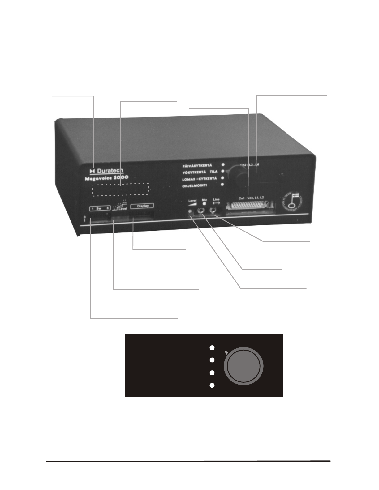
The line level is adjustable from the front panel.The front panel dip switches are used for
special cases and are not needed normally. Front panel has also connector for separate
or internal 32 character LCD display. It helps to program, study and read the system
programming. It also indicates the incoming calls counter and displays free and used
memory. Front panel has three leds; green, yellow, red like traffic lights. Normal green
lights and everything is OK. Yellow indicated wait and red error. These leds indicated
also the recording level: green OK, yellow OK, red too high.
Basic unit can be expanded with expansion port. It can use for example 4 extra lines.
Also there are many options: V.24 port for maintenance, real time clock, IO-port, cellular
phone interface, relay outputs. Custom made interfaces are available on request.
.
Megavoice basic unit can store up 128s messages and the capacity can be extended to
256 s or more. There are 2 lines L1 and L2. Messages are message1...message 9.
( >=V3.0 , M9 is guiding message).
Megavoice is has low power consuption. It operates between 11-60Vdc. The power unit
has low voltage detection /shut off for lead acid battery systems for 12/24/48 V. Basic
unit draws only 2.5W normally. Also mains AC/DC power supply can be used and is
supplied with the unit.
Megavoice operates in normal office type place. Temerature limit is +5...50C, 0...90%
RH, normal radiation, normal air pressure, max 1g. Size is 259x195x85 mm and weight
apx.1 kg.
1
MEGAVOICE 2000 V.3.1 MANUAL V.2000-09-20

2
1.2 STRUCTURE OF MEGAVOICE
Expansion slot
Cable connector Cn1
-Power
-grounding if needed
-Line 1 and 2
Interface for
line recording
Connector for hand set,
for recording and
monitoring
Input level adjustement
Connector for
display and V.24 port
Indicators
-Green / Yellow/red
-functions OK, wait, error
-Recording level meter
low, satisfactory, too high
Front panel switched Sw1 ...Sw8
-Control special functions
-normally not used
A expansion place
for display
The name
and model
Under the unit there may be hidden installation bar.
All right are reserved. Specifications may change during the product development
DAYMODE
NIGHT MODE
VACATION
PROGRAMMING
Mode switch
2MEGAVOICE 2000 V.3.1 MANUAL V.2000-09-20

Power cable Lenght 2 m
Line cable 2
Line cable 1 Blue mark
Installation cable kit
Power cable Lenght 2 m
Line cable 2
Line cable 1 Blue mark
Installation cable kit
LINE CABLES
6-wire flat cable, 0.14mm2 . No metallic screws. Color code 1-6: blue,yellow,green,
red,black,white.Flat cable can be conncted to RJ-connectors, which can have adaptors.
D25 female connector.
Cable1, Line 1, has blue mark.
pin Pair Color Signal
12 1. Green Teleline a-wire, acts also as a 600 ohm line interface.
13 Red Teleline b-wire
24 2. Yellow CTI-card output a-wire, for continuos tele line
25 Black b-wire
1 3. Blue M input, (Mouth, Start, V+ control input , 8...60 V )
2 White E output, (Earth, Busy, V+ control output, 2...60V )
Cable 2, Line 2
pin Pair Color Signal
10 4. Teleline a-wire
11 Red
22 5. Yellow
23 Black
14 6. Blue M input
15 White E output
POWER CABLE 2
4-wires flat cable 0.14 mm . Power connector 2.1 mm female DC-connector, middle contact
V+. Connected to power supply. Secure DC-connector with cable strap.
D25 Pair Expanation
6 (7.) Green, V-, (-48V system -48V).
8 Red, V+, (-48V system 0V, ground ).
5 Frame ground
4 V- out, D25/3 is E&M system V- input. Connect together is E&M used.
17 V+ out, D25/16
16 E&M system V+ input, used only for E-wire pull up.
3 E&M system V- input, Only used for E&M.
D25-connector: 19-20 connected, Operation voltage is 12V (11-24V). As default setting
If 19-7 connected and 19-20 are not , Voltage is 24V. If 20,19 ja 7 not connected means
voltage is 48V.
Green Teleline b-wire
is E&M system V+ input. Connect together is E&M used.
3
1.3 SCHEMATICS 1, CABLE KIT VERSION 1.
MEGAVOICE 2000 V.3.1 MANUAL V.2000-09-20

Power cable Lenght 2 m
Line cable
CABLE KIT
Power cable Lenght 2 m
Line cable
CABLE KIT
L
CABLE 1 : Lines 1 ja 2.
pin Pair Color Signal
12 1. Green Teleline 1. a-wire, Acts also as 600 ohm interface.
13 Red Teleline 1. b-wire
24 3. Blue 600 Ohm/teleline a-wire, CTI line.
25 White 600 Ohm/teleline, b-wire, CTI-line
OTHER LINE INTERFACES IN D25 :
pin Pair Color Signal
22 Yellow Not connected.
23 Black N.C.
14 Blue 2-liune, M input
15 White 2-line, E output
INE CABLES
6-wire flat cable, 0.14mm2 . No metallic screws. Color code 1-6: blue,yellow,green,
red,black,white.
Flat cable can be conncted to RJ-connectors, which can have adaptors. D25 female
connector.
10 2. Yellow Teleline 2. a-wire, Atcs also as 600 ohm interface.
11 Black Teleline 2. b-wire
1 Green 1.line M input, (Mouth, Start, V+ control input , 8...60 V )
2 Red 1. line E output, (Earth, Busy, V+ coltage out, 2...60V )
POWER CABLE 2
4-wires flat cable 0.14 mm . Power connector 2.1 mm female DC-connector, middle contact
V+. Connected to power supply. Secure DC-connector with cable strap.
D25 Pair Expanation
6 (7.) Green, V-, (-48V system -48V).
8 Red, V+, (-48V system 0V )
5 Frame ground
4 V- out, D25/3 is E&M system V- input. Connect together is E&M used.
17 V+ out, D25/16 is E&M system V+ input. Connect together is E&M used.
16 E&M system V+ input, used only for E-wire pull up.
3 E&M system V- input, Only used for E&M.
D25-connector: 19-20 connected, Operation voltage is 12V (11-24V). As default setting
If 19-7 connected and 19-20 are not , Voltage is 24V. If 20,19 ja 7 not connected means
voltage is 48V. 2
Note 1.: LSA+ accepts 0.13-0.5 mm cable. Line cables can be used with it.
Note 2.: Typical pair numbering is marked above.
4
1.3B SCHEMATICS 2 . CABLE KIT. VERSION 2.
4MEGAVOICE 2000 V.3.1 MANUAL V.2000-09-20

1.4 FUNCTIONING
Megavoice has 4 different modes : day 1, night 2, vacation 3 and programming 4.
Every line has separate messages and line type (functioning) in each different
Megavoice mode. The line functioning can be adjusted to work with nearly any
equipment. Megavoice programming lines can be connected together. Then only the
right megavoice with right password do not hang up.
1.5 EXAMPLE 1, ANSWERRING MACHINE AND MUSIC ON HOLD AND REMOTE
MAINTENANCE,
Line 1 and 2 are connected to extentions 207 and 208. Line 1 has type 16 and line 2
has 128. Line 1 answers and gives informative announcenment “ Our office hours are
… “ Line 2 in a Music on hold source for the PABX. The system can be programmed
with line 1 with login-command before the messsage starts.
1.6 EXAMPLE 2, E&M LINES WITHOUT E-LINE (Busy) DETECTION
Line 1 and 2 are connected to PABX E&M-lines. Line types are 25. The message starts
when there is a start pulse via M-wire. Megavoice has CTI-line connected to 1srt E&M-
signal pair. 1st Teleline is connected to extention. Remote programming is done using
L1 teleline and other times the E&M -messages operate normally.
1.7 EXAMPLE 3, E&M WITHOUT M-SIGNAL (start)
Line 1 and 2 type 144. Both lines give continous message on E&M lines. E-wire
indicates when the message is on and a short off state when the message starts again.
1.8 EXAMPLE 4, CONTINOUS MESSAGE AND REMOTE PROGRAMMING
Line 1 has CTI-circuit. CTI-is connected to extention 208. L1 teleline is connected to
207. Line 2 is connected to 209. Line 1 type is 153, line 2 has type 128. CTI-line and L2
gives continous message but it is possible to call for programming the L1 teleline.
1.9 EXAMPLE 5, TRANFERRING MACHINE
Line 1 has type 50 and answer delay is 2 and it is connected to 207 The transferring
number is 0 04001223456. The message 1 is “ the call is been transferred, please hold
on “. All calls are transferred and the user can change the transfer target number using
remote programming. This is follow me service
1.10 EXAMPLE 6 TRANSFERRING MACHINE AND NIGHT MESSAGE
Line1 has type 50, answer delay is 1 and extention number is 207. All calls go to 207.
Transferring target number is 55, which is a extention series having extention 208. Line
2 ihas type 50 , answer delay 10 and transfer target is 55 and it is conncted to 208.
Line 1 wellcomes Message 1“ This is telephone service” and is there is no answer
there is a another message from line 2 after apx 50 s message 2 “You are still on a line.
Please hold on”. During night time L1 has type 16 and message 3, which is “ Our office
hours are … Please call again”.
5
MEGAVOICE 2000 V.3.1 MANUAL V.2000-09-20

6
1. 12 EXAMPLE 8, RUSH HOUR MESSAGE AND MUSIC ON HOLD
L1 has a type 50 ( delayed answer, tranfer) and the answer delay is 5 and the transfer
number is 18. L1 is connected to an extention that ring parallel to operator, whose number is
18. L2 has type128, continous message. It gives music on hold to an extention continously.
If the operator 18 do not answer within apx 25s the system answer “ Our swich board is
busy. Please hold on.” and the call is transferred to operator till she can answer the call.
During night time the line 1 can give immediate answer and night message. The queuing to
the operator stops when the ISDN line releases the line when caller hangs up.
EXAMPLE : Siemens 100 PABX sends DTMF after *53 command. Extention number here is
43.
PROGRAMMING
Switch is placed into Programming state. Line 1 is called with 43. Megavoice answers and
gives voice guide. The system programming may start.
Line set up.
50 1 50 1#, 50 1 48 2#, 50 1 48 3#, 50 1 48 4 #.
52 1 1 1#, 52 1 3 2#, 52 1 5 3#, 52 1 7 4#
56 1 18# , 18 is the extention of the operator.
57 1 5#, There is a 5x5 s delayed answer
Line 2 is set up.
50 2 128 1#, 50 2 128 2#, 502 128 3#, 502 128 4#, All modes has MOH.
66# . Setup is stored
Message 1,2 and 3 are recorded.
Erase old recording with 1 m# command.
Record new message m with 2 m # using telephone. The music may be entered with line
interface also.
Check the recordings with play back 3 m # command.
Msg 1 = Day rush hour, line 1. “Our switch board is busy. Please hold on . “
Msg 2 = Music on hold, Continous music in all mode.
Msg 3 = Night information message “ Our switchbourd is open … . Please call again.“
Msg 5 = Vacation message “ During Xmas time our office is open .... “
The mode switch is placed into Day mode. The line is hung up.
Test the installation.
1.11 EXAMPLE 7, PREANSWER
Line 1 has type 48 , target transfer number is 9 and and extention number is 207. L1
answers “ This is … company, please hold on” and transfers the call to operator, 9. During
night time the L1 answers with night message 3 “Our office hours are”. Line 2 has type 128
and it acts as a music on hold source.
V VV V VV V VV V VV
VVVVVVVVVVVV
VV
VV
V VVV VVVVVVVV
V
Chech the recording with V3 m #.
V
V
V
6MEGAVOICE 2000 V.3.1 MANUAL V.2000-09-20

2. RECORDING
The messages of the announcer must be recorded and stored before use. Usually the
spoked masseges are stored using normal telephone. The unit is controlled with DTMF-code
commands. Also it is possible to enter recording using line interface in the front panel from
CD or tape recorder.
In order to program the user must enter programming state. 1-way : It can be reached by
using the front panel Program-switch, and calling the 1st line. The unit gives spoken voice
guide. The programming mode is ended when the switch is placed into another position. This
requires that the unit is in default position or programmed to operate this way. 2-way is that
the unit called using 1-line. When the unit answers the user gives V0 <password># command
and enters the programming state. The programming state is ended with ‘0# command.
Megavoice can have up to 9 messages 1...9. Here a message number is indicated using m.
Message 9 is voice guide. Installer sets up or uses the default values to control the unit give
certain message on certain line or certain mode (day/night/vacation/program). The old
messages is played back with V3 m #, like V 31# for message 1. Message is removed with
V1 m # and new message is recorded with V2 m #. Recording and playback stops with #.
The recording level is suitable when the red led flashes now and then. The programming
messages are decribed in the Programming section of this manual.
RECORDING TECHNIQUES
The recordings can be entered with telephone call, head set mic-connected directly to
Megavoice, with line level ( 0.8 V) interface from CD or recorded or PC. The operations are
controlled in all cases using line 1 with a DTMF telephone. The levels or the mic and Line
interface can be adjusted with a level setting in the front panel. The best result can be
reached using front panel line interface but telephone is usually adequide. The recordings
can be edited using PC or recorders. With suitable sofware the voice can be compressed and
mixed for the telephone lines but this needs some knowledge. Many times the recordings can
be mixed acustically ; the back ground music can be recorded using CD-player playing on the
back ground on the desk. This takes some test runs but it works well.
The Megavoice has a very sharp band pass filter (apx. -50 db/oct) from 230...3400 Hz. The
front panel level meter leds indicate the digitized signal with this filter and indicates the real
digital audio level recorded. Red led is -9dBm, yellow is -17dBm, green is -23dBm. -9Bd is
apx. the level of the dial tone in the telephone network which is usually the target level of the
messages. It is good idea to compare own recordings with dial tone. Also an ear is more
sensitive to higher frequencies and it has to be compensated sometimes by lower the level.
Usually the recording level is ok if the red led flashes occasionally. Automatic level
adjustement is not used because it can not be controlled well. 0dBm=775mV @ 600 Ohm
here.
If PC software compression is used, cut the low (<200Hz) and high frequncies (>3400Hz)
before compression ( normalisizing). Good results are obtained using 1:4 compression for
telecom network.
7
MEGAVOICE 2000 V.3.1 MANUAL V.2000-09-20

3. INSTALLATION
3.1 MECHANICAL INSTALLATION
Megavoice is placed into a suitable place and line cable kit is connected to the D25
connecter in the front panel. The power supply is connected. The extention line are
connected to the line cable. See schematics for details. One line can be connected to
tele line or 600 ohm line. Also E&M signaling can be used. A additonal 2x16 character
display can be connected to Display-connector.
3.2 QUICK START
GENERAL
- OK is 2 beeps,
- Wait/infomation tone is one beep,
- Error tone is 9 beeps.
- All commands start with Vand end with #. Detailled commands are in installation
manual.
1. Install Megavoice cables.
1B If front panel mode switch is used : Place mode switch into Program state.
2. Ring line 1. Its extention number is _____________. ( Installer fills in)
If necessary dial DTMF sending start prefix _________ ( == )
3A. If mode switch is used : Wait for 2 beeks, OK.
3B. Else : Dial V 0 pppppp #, (login) immediately the device answers. Password here is
pppppp, see 3.4. Programming state is reached this way. If password is not used V0 #,
can be used. Megavoice answers with OK beeps. If not try call again.
4. Play an old message 1.
Dial command V 3 1#. Device plays back message 1. This way m -message is played
back with V3 m # command. # stops playing
5. Erase old message 1. Dial V1 1 #. This way m-message is erased with V1 m #.
Device beeps till it gives OK beep. Message 9= guiding tone and it can only be erased
with switch 8 =1.
6. Record message 1.
Dial command V2 1#. Wait 2 s for a start beep and record new message with a hand
set or CD with line connector. Stop with #. Device gives then OK beep. If error or out-of-
memory-error it gives error-tone.
7. Repeat steps 4...6 for necessary messages. The meaning of different messages are
hopefully written by installator to chapter 3.4
8. Now installer can enter other set ups. The line answer/delays, transfer target
numbers etc. must be entered. The set ups must be stored with *66# into non-volatile
memory in the end for power failures.Recordings are always stored.
9. Finally exit the programming state.
9A. If mode switch is used : Switch it off the Programming state and it cuts the line.
9B. Else: With V 0 # command or the device logs out after 222s of no-commands-state.
10. Test the installation.
88 MEGAVOICE 2000 V.3.1 MANUAL V.2000-09-20

9
3.4 MEGAVOICE2000- INSTALLATION DATA
PLACE : ________________________________________________
PABX TYPE : ________________________________________________
LINE 1 EXTENTION :_________________ LINE 2 EXTENTION :_________________
PABX DTMF START CODE : ___________________
MESSAGE : MEANING
MESSAGE 1 :
_______________________________________________________________________
_______________________________________________________________________
MESSAGE 2 :
_______________________________________________________________________
_______________________________________________________________________
MESSAGE 3 :
_______________________________________________________________________
_______________________________________________________________________
MESSASE 4 :
_______________________________________________________________________
_______________________________________________________________________
MESSAGE 5 :
_______________________________________________________________________
_______________________________________________________________________
MESSAGE 6 :
_______________________________________________________________________
_______________________________________________________________________
MESSAGE 7 :
_______________________________________________________________________
_______________________________________________________________________
MESSAGE 8 :
_______________________________________________________________________
_______________________________________________________________________
MESSAGE 9 :
_______________________________________________________________________
VOICE GUIDE V 1 message number # is erasing, V 2 msg number # is recording,
V3 message number # is play back …
Message 9 can only be erased with sw8 down.
MEGAVOICE 2000 V.3.1 MANUAL V.2000-09-20

LINE 1 :
1 DAY *50 1* _________*1# (50) *52 1*__________*1# (1)
2 NIGHT *50 1*_________*2# (16) *52 1*__________*2# (3)
3 VACATION *50 1*_________*3# (16) *52 1*__________*3# (5)
4 PROGRAMMING *50 1*_________*4# (16) *52 1*__________*4# (7)
TRANSFER TARGET NUMBER *561* ____________________#
ANSWER DELAY (RINGS) *571* _____________# (1)
LINE INTERFACE: TELELINE ______/ 600 ohm_______ / E&M _______
INTERNAL CTI-CARD INSTALLED (Yes/No) _______________ (Y)
LINE 2 :
1 DAY *50 2* _________*1# (50) *52 2*__________*1# (2)
2 NIGHT *50 2*_________*2# (16) *52 2*__________*2# (3)
3 VACATION *50 2*_________*3# (16) *52 2*__________*3# (6)
4 PROGRAMMING *50 2*_________*4# (16) *52 2*__________*4# (7)
TRANSFER TARGET NUMBER *562* ____________________#
ANSWER DELAY (RINGS) *572* _____________# (1)
LINE INTERFACE: TELELINE ______/ 600 ohm_______ / E&M _______
SYSTEM :
Flash time ( x 10ms ) *59 1*__________# (12)
Delay flash-number( x 100ms ) *59 2*__________# (10)
Delay Answer- ( x 100ms ) *59 3*__________# (20)
MODE SWITCH ( 01=no /02=used ) *59 4*__________# (03)
(03=used, prog state no login )
MV TYPE (01=Transfering machine) *59 5* __________# (01)
PASSWORD *7 _________________# ( )
EQUIPPED WITH INTERNAL MODE SWITCH ( Y/N ) _____________(Y )
EQUIPPED WITH EXTERNAL MOE SWITCH (Y/N ) _____________
MEMORY EXPANSION (Y/N + capacity S ) _____________________(N)
POWER VOLTAGE (12/24/48 VDC /230VAC) _____________________ (12V)
SERIAL NUMBER: _____________________
FRONT PANEL SWITCHES ( 1/0 ) :
1_____ 2_____ 3____ 4____ 5____ 6____ 7____ 8______ (00000000)
* Defaults are inside brackets ( ).
1010 MEGAVOICE 2000 V.3.1 MANUAL V.2000-09-20

11
3.5 FRONT PANEL MODE SWITCH
Megavoice can be equipped with a front panel mode switch. Is sets MV into
day/night/vacation/program mode. There are 4 modes and mode controls freely which
message is used and how does a line operate. The switch is activated by 594 3#
command. Many times the unit is progammed so that when mode is Program, a call to the
1st line enters the programming state directly and the unit gives voice guide explaining
different commands. Voice guide repeats every 45s is nothing is done. The programming
mode can be existed turning the switch off the Program state.
EXAMPLE :
-In day mode he unit answers calls directly, announces a service number message and
transfers the call into extention group.
-In day mode the unit answers and gives night message and hungs up.
-In vacation mode the unit gives adjustable vacation message and hungs up.
-In program mode the unit answers and enters programmin state and exits it when
swithed off it.
VV
A picture of the mode switch
3.6 DAY/NIGHT CONTROL
Megavoice 2000 can be also set into day/night/vacation mode by remote control if the
mode switch is not used. First line is called and a right command is entered immediately
when megavoice answers. The Programming mode is not needed in this case. The right
command can be programmed into speed dialing or programmable key of the telephone
set. The state can be tested by callin megavoice again. If state is not correct, the
programming of mode can be redone. See commands starting with 4 if necessary
EXAMPLE 1 :
Call Megavoice 1st line using __________________
and after 2 s
-For day mode : press key tagged “Day mode “.
-For night mode : press key tagged “Night mode”.
-For vacation mode: press key tagged “Vacation mode”.
EXAMPLE 2 :
Call Megavoice 1st line using ___________________________.
and wait for 2 s and press then :
-For day mode 41 111#
-For Night mode 42 111#
-For Vacation mode 43 111#.
Note: Here the password starts with 111... .
V
V V V
V V V
V V V
.
DAYMODE
NIGHT MODE
VACATION
PROGRAMMING
MEGAVOICE 2000 V.3.1 MANUAL V.2000-09-20

4. PROGRAMMING
4.1 GENERAL
Megavoice is controlled with DTMF codes. One command starts with and ends with #.
Different fiels are separated by except 1st one which is line number. If value field is ,
Megavoice displays the value. can have also other meanings like all lines like 1 #.
Eg. Play back message 1 is 3 1 #.
Megavoice replays with 2 beeps=OK-tone, or with 9-beeps=Error-tone, or 1beep= wait/
information tone.Eg. Device gives information tone before and after playing one
message with play command. Then the lenght of the message can be timed exactly.
LCD display indicates error and Ok and many useful information, like free memory,
parameter values, or how many calls per line. The maintenance and learnig is easier
with display. If remote programming is used, the first command is login and the last is
logout. Megavoice logouts if no command are used for 3 minutes.
The set up data must be stores with 66 # into non-volatile memory for power failures at
the end of installation. Line counters are backed up every 24h. Remote mode changes
are immediately stored.
Megavoice has 1 lines. They have 4 modes : Day/night/vacation/programming. There
are 9 possible messages. During installation the functioning of the line must be
programmed; direct/delayed answer AND information or message+transfer+number.
Also the message given in different line/mode states must be entered. Default values
can be used, which saves some work.
4.2 FRONT PANEL SWITCHES
The front panel switches are not usually used,
but can be used in special cases.
Switch 5 : If down(1) and Megavoice is power up, the factory set up values are used and
they can be stored.
Switch 6: If down(1), Megavoice do not wait extra 1s between commands to indicate
value in the LCD.
Switch 7: If down(1), the programming mode is not timed and there is no automatic
release. Also if 594=3 and sw7=1 (on), L1 is in the programming state
immediately. The programming can be done with CD player script on L1.
Switch 8 : If down (1), All passwords are accepted as 0 # command. Also must be
down if message 9 or all messages are erased.
V
VV
V V V V
V
V
V
V
12
OFF
ON 1 2 3 4 5 6 7 8
0
1
1 SW 8
12 MEGAVOICE 2000 V.3.1 MANUAL V.2000-09-20

5. MEGAVOICE COMMANDS V.3.0
This expains the different commands. First is syntax, then fields are explained, then notes.
5.1 LOGIN INTO PROGRAMMING STATE 0
0 n n n n n n # OR 0 # if password is not used. Read notice.
,nnnnnn=password with 6 numbers. Default nnnnnn= <is not written here, see 3.4>.
Display : Before command "Login".
Device : Line 1 is called. Some PABX require that a function code is now entered to start
DTMF-sending. It is stated is the PABX manuals. Wait for megavoice answer.
Dial 0 nnnnnn #. Megavoice sends OK-beeps, green led is lid and the display indicated
"Enter command". The message of the line is halted. When megavoice answers the line, it
waits for 2 second before it starts its message. Dial this comand immediately the Megavoice
answers. The Spoken message wmay interface with the Dual-Tone-codes.Eg. 0 123456 #.
Note : If mode switch is activated with * 594* 3# (as default )and the device is in PROGRAM-
state, 0 # is not used for login. Megavoice answers then and goes directly into programming
state and gives 2 beeps= OK
5.2 LOGOUT OF THE PROGRAMMING STATE 0
0 #
When used during programming, program exits the programming state and hangs up.
Display indicates "logout " followed by "login". Eg. 0 #.
Note : If Mode Switch is activated by 594 2# or 594 3# commands AND the Mode
Switch is in Program-state, THEN the line is hung up if the switch is changed into other state.
Useful to exit the programming state.
5.3 ERASE MESSAGE 1
1 m #
m= message number 1... muodossa. If m= clear all messages (= command 1 #).
Default is all messages empty. Guiding message 9( and all) can be erased only if sw8 is
1=down.
Megavoice : Beeps once for every 8 s erased. When ready beeps twice as OK-tone. Error
tone (9-beeps) is given when there is an error. Eg. Erase message 1 is 1 1 #.
5.4 RECORDING MESSAGE 2
2 m #
m= message number 1...9
Megavoice : Gives one beep 2 s after this comend to indicate start of recording. Recoring is
stopped with # command or with 9-beeps error tone is memory is full or message is not
empty. # beep is not recorded.
The front panel leds acts as UV level meter. The red led may occasionally flash during
recording. Recordings are stored into chip memory for 20 years. See also chapter Recoring.
Message must be erased before recording a new one. Eg. Record msg 1 is 2 1 #
Eg
5.5 PLAY MESSAGE 3
3 m #
m= Message number 1...9 . Command plays back a recorded message.
megavoice : Gives on wait-beep and play message mm , ends with wait -beep, and gives
OK-beeps.
Display indicates the number of the message. Play back can be halted with #.
Eg. Play message 1 is 3 1 #. Play message 2 is 3 2 #
VV
V
V
V
V
V
VV VV
V
VV V V V
V
V
V
Dial V 2 1 #, wait for a beep, record and stop with #. Play back it with V3 1#. (See 5.5)
V
VV
13
MEGAVOICE 2000 V.3.1 MANUAL V.2000-09-20

5..6 MODE DAY/NIGHT 40/41/42/43/44
There is a handy command :
40 c m # , Sets line c into state m.
40 m # , Sets all lines into state m.
Without programming state, there are commands:
40 nnn # , night mode for all lines
41 nnn # , day mode fro all lines
42 nnn # , night mode for all lines
43 nnn # , vacation mode for all lines
44 nnn # , programming (4) mode for all lines.
Note : above commands do not operate in the programming state.
c= line number 1... (one digit). If value is means for all lines.
nnn= First 3 digits of the password. Default is 111.
m= mode 1,2,3,4. 1=day, “=night,3=vacation and 4 is programming state.
When the mode is changed it is automatically stored into non-voltatile memory for power
failures.
Eg:
40 1 # set all lines into day(1) mode.
40 2 # sets all lines into night(2) mode.
40 3 # sets all lines into vacation mode.
41 111 # sets all lines into day mode without entering programming state.
42 111 # sets all lines into night mode without entering the programming state.
43 111 # sets all lines into vacation mode.
The front panel mode switch is connected to sw1 and sw2. M1 input sets sw1=1 and M2
input sets sw2=1. In day mode sw1=0, sw2=0, in night mode sw1=1,sw2=0, in vacation
mode sw1=0, sw2=1 and in programming mode sw1=1, sw2=1. If front panel mode switch
is active and placed into day position or not equipped at all, the device mode can be
remotely controlled with M1 and M2. Also M1 and M2 can be tested with sw1 and sw2.
Sw1=1 means switch sw1 is in ON position.
5.7 RESET INCOMING CALL COUNTER
45 0 #
Command resets all incoming call counters to 0. The call counters are stored every 24h
for power failures. The counter counts 0...50000 and then starts from 0.
If display is used the counter is displayed on the 2nd line.
5.8 NOTE
If commands 5 have value , the current value is displayed.
5.9 RESERVED
V V
V V V
V V V
V V V
V V V
V V V
V V V
V V
V V V
V V V
V V V
V V V
V V V
V V V
V V V
V V
14
14 MEGAVOICE 2000 V.3.1 MANUAL V.2000-09-20

5.10 LINE TYPE 50/51
V 50 c Vtt Vk # , Set Line c, Type tt, in mode k.
V 50 c V V k # , Display line c type tt in mode k.
V 50 c Vtt # , Set type during night mode
V 51 c Vtt # , Set type during day mode
c = line number 1...6.
tt = type 00...255 . If V V =display the value.
k = modei 1,2,3,4 ( day,night,vacation, programming)
tt builds up from the following sum.
128 = Continous message (start), auto start after release.
64 = pulse dialling (reserved, not used )
32 = Transfer the call after a message
16 = Teleline and E&M-line is released after the answer, hung up after a message.
Then there is 250ms pause (on E-line) before next active state.
08 = The line is E&M-type.
04 = Reserved , for line monitoring
02 = Answer with a ring delay indicated by V56cVn#-command. Default delay is 1.
01 = Teleline answer on L1 possible during even on E&M-on-state. L1 do not switch
teleline or 600 om line ON (for CTI-line)
Example Ready types :
Type tt Description
0 153 Continuous message on CTI-line, answer on 1 line call.
1 144 Continous message, E&M. Meridial etc.
2 128 Continous message and loop current on teleline
3 16 Call is answerred directly, message given and line released after that.
4 18 Call is answerred with a delay, message given and then released.
5 48 Call is answerred, message given and the call is transferred with a flash.
6 50 Same as 48 but with a delayed answer.
7 25 E&M on L1 with CTI-line.Teleline answer is possible for remote control.
8 24 E&M-line controlled message line. Meridian, MD etc.
9 09 The message starts if 5 V is received on E-wire. Also teleline
answer/programming is possible.
After a command Megavoice gives OK tone and displays CH=cc TYPk=tt.
When line 1 answers there is a 2 s delay before the message starts for entering the
programming state.
15
MEGAVOICE 2000 V.3.1 MANUAL V.2000-09-20

5.11 LINE MESSAGE 52/53
V 52 c V m V k # , Set line c to have message m during mode k.
V 52 c V V k # , Display line c message m during mode k.
c = Line number c (1...6)
m = Message number m.. If V, display the value.
k = modei 1,2,3,4 ( day,night,vacation, programming)
As defauls the message of line in different modes 1,2,3,4 ovat ; L1 =1,3,5,7 and
L2=2,4,6,7.Megavoice replays with OK tone and displays CH=cc MSG=mm.
5.12 LINE LEVEL 54/55
V 54 c V n # , LINE c output reference level, small number is low level.
V 55 c V n # , LINE C input reference level. Small number is high sensitivity
c = Line number (1...6)
n = digit 1...9. One number is 3 dB. If *= display the value.
Default output level is 8 and input is 6. 8 ja sisään 6. The level meter is adjusted with
these values. The level adjustment is not recommended.
Megavoice replays with OK tone and displays after 54 L=cc OUTL=nn and after 55
L=cc IN-L=nn.
LINE L Value *54, default Value *55, default .
1 86
2 86
5.13 LINE TRANSFER NUMBER 56
V 56 c Vnnnnnnnnnnnnnn # , Enters the transfer target number
c = LINE (1...6)
nnnnnnnnnnnn = telephone numbers using 0...9. Default is empty. If n=* display the
number.
The transfer target number of the line is entered. Megavoice replays with OK tone and
displays the number.
See. 5.16.
1616 MEGAVOICE 2000 V.3.1 MANUAL V.2000-09-20
This manual suits for next models
1
Table of contents