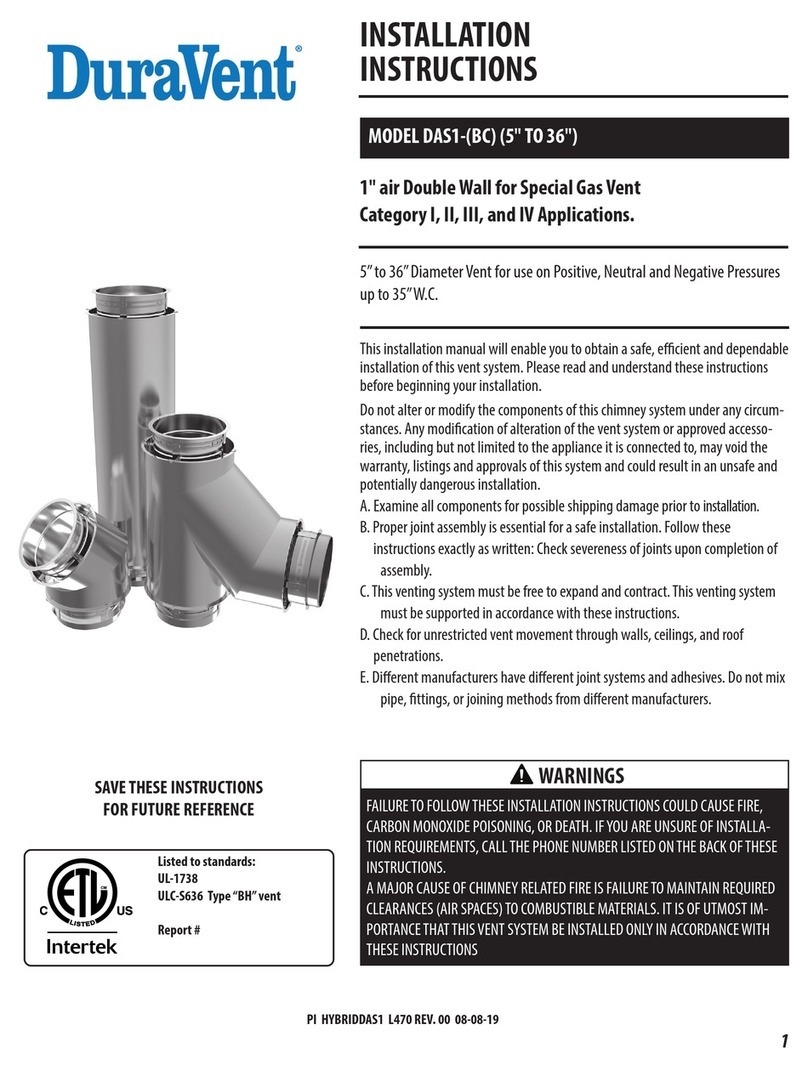
DuraVent DURASTACK PRO DAS1 Series User manual

M&GDURAVENT
S
UBMITTAL
R
ECORD
|
DAS1,
DIS1,
DIS2,
DIS4,
DCL J
ANUARY
2016
DURASTACK™PRO
P
OSITIVE
P
RESSURE
S
YSTEMS
M
ODELS
DAS1
–
1
INCHAIRINSULATED
DIS1
–
1
INCHCERAMICFIBERINSULATED
DIS2
–
2
INCHCERAMICFIBERINSULATED
DIS4
–
4
INCHCERAMICFIBERINSULATED
DCL
–
SINGLEWALL
MATERIAL
SELECTION
FLUE
(INNER
WALL)CASING
(OUTER
WALL)
304304
316441
GALVALUME
PROJECT:
PREPAREDBY:
PREPAREDFOR:
BoilerBreechingandStack
Generator|EngineExhaust
FumeVenting
FireplaceVenting

1SUBMITTALRECORDFORDURASTACKMODELSDCL,DAS1,DIS1,DIS2ANDDIS4
M&GDURAVENT|10JUPITERLANE|ALBANY,NEWYORK
www.duravent.com
DURASTACK™PRO
MODELS D
CL,
DAS1, DIS1, DIS2, DIS4
DCL- SINGLE WALL
DAS1- AIR INSULA
TED
DIS1, DIS2, DIS4 – FIBER INSULATED
SECTION A
-
CODE C
OMPLIANCE
UNDERWRITERS LABORATORIES
LISTINGS
DURAVENT
single wall Model DCL and double wall models DAS1
, DIS1, DIS2 and DIS4
venting systems are
listed by Underwriters Laboratories, Inc. (UL) in the following
product categories and in
the diameters indicated:
Model DAS-PRO
(DAS1 - Doublewall,
1”
air
insulation)
Building Heating Appliance Chimney
5”-
36” ID
1400° Fahrenheit Chimney
5”-
36” ID
Models D I S - PRO
(Doublewall, DIS1, DIS2 or DIS4) where the number
equals ceramic fiber insulation thickness
Building Heating Appliance Chimney
5”-
36” ID
1400° Fahrenheit Chimney
5”-
36” ID
Building Heating Appliance Chimney(Type HT)
5”-
36” ID
APPLICA
TION
UL 103 Building Heating Appliance Chimney
Listing:
Under this category, models DAS-PRO and DI S -PRO have been determined suitable
for
venting flue gases at temperatures not exceeding 538°C (1000°F) under
continuous
opera
ting
conditions from gas,
liquid,
oil or solid fuel fired appliances. Also
complies with opera
tion
(less than one hour) at temperatures not exceeding 740°C
(1400°F) and brief
opera
tion
(maximum 10 minutes) at temperatures not exceeding
906°C (1700°F).
Building
Hea
ting
Appliance Chimneys are suitable for use with
Building Heating Appliances and Low
Hea
t
Appliances as described
in
the Chimney
Selection Chart
of
National Fire Protection
Association (NFPA) Standard NO. 211.
Building Heating Appliance Chimney (Type HT) Listing 5” to 24” DIS-PRO
ONLY
Under this category (UL 103HT), the 5”
through 24” ID DIS-PRO Models have qualified
for
UL
’
s
additional, optional “Type HT” rating (for Building Heating Appliance
Chimneys) which
indicates they have been evaluated and found suitable for exposure
to 2100°F flue gases
for a 10 minute duration at a specific clearance for each
Model and diameter. Many local, state and regional code authorities require a
“Type HT” rating for chimneys for certain appliance venting applications; especially
solid fuel.
Building Heating Appliance Chimneys are suitable for use with
Building
Hea
ting
Appliances and other Low Heat Appliances as
described in the Chimney Selection
Chart
of National Fire Protection Association (NFPA) Standard No.
211.
1400°F Chimney Listing
-
Under this category (UL 2561,ULC-C959), Model D A S -
PRO
and DIS
X-PRO
have been determined suitable for venting flue gases continuously
at a tempera
ture
not exceeding 1400°F, and a 10 minute intermittent service at
temperatures not
exceeding 1800°F. As such, Model DAS-PRO and D I S -PRO
Models are suitable
for
use with ovens and furnaces as described
in
the Chimney
Selection Chart
of
NFPA No. 211, in
addition
to
other
A
pplications.
Engine Exhaust
Based upon the above referenced UL Listings and supplemental, UL
confirmed
pressure
testing, Model D A S -PRO and D I S -PRO are also suitable for use as
complete exhaust systems for
diesel engine and gas turbines. When Model DAS-PRO
and DIS-PRO
is
used as an engine or turbine
exhaust it is intended to be installed in
accordance with
NFPA
37
“Stationary Combustion
Engines and Gas Turbines”. This
code states, “When such (flue gas) temperatures do
not exceed 1000°F (538°C)
except
for
infrequent, brief periods, the engines shall be classified as low heat
appliances”. For continuous operation over 1000°F and not exceeding 1400°F the
exhaust system should be installed as a 1400°F
Chimney
.
Models D I S -PRO
may be used to meet various needs,such as:
a) Reduce outer pipe surface
tempera
ture.
b) Reduce building heat gain by retaining energy inside the vent.
c) Increase the efficiency of energy recovery systems by reducing exhaust
gas temperature losses.
d) Increase chimney or exhaust system draft loss performance due to
reduced exhaust gas temperature drop.
e) Reducebuilding noise levels caused by high speed or pulsating exhaust
induced noise. NOTE:
Specific tests have not been conducted to measure
acoustic performance.
Models DAS-PRO and D I S -PRO exhaust systems are intended for use in
connecting
the
hea
ting
appliance, engine, or turbine to the outdoors, while operating under
positive forced draft,
negative induced draft or neutral gravity flow internal
pressure conditions. Models DAS-PRO
and DIS-PRO (all insulation thicknesses)
may be intermixed
in
the same chimney system, assuming the proper associated
airspace clearances-to-combustibles are maintained.
ADDITIONAL
APPLICA
TIONS
Models D CL, DAS1 and DIS-PRO are also suitable for negative, neutral or positive
pressure
pre-
fabricated piping systems intended for use in a variety of
applications including but not
limited to the following: Fume Venting, Chutes,
Particle Conveying, Dr
yer Vents and Ventilation Ducts.
SUITABLE FOR POSITIVE PRESSURE VENTING APPLICATIONS WITH MAXIMUM 60”
WATER COLUMN INTERNAL STATIC PRESSURE AT 1000 DEGREES F
.
MULTI-ENGINE
EXHAUSTS
A common exhaust system
for
multiple engine or turbine installations
is
generally not
recommended. Check with your engine or turbine manufacturer prior to
common
exhaust system design. Exhaust gas from operating units tends to flow to
non-
opera
ting
units where condensation may form. Water in engine or turbines at start-up
may cause damage. In general, a separate exhaust system should be provided for
each engine or turbine
.
2SUBMITTALRECORDFORDURASTACKMODELSDCL,DAS1,DIS1,DIS2ANDDIS4
M&GDURAVENT|10JUPITERLANE|ALBANY,NEWYORK
www.duravent.com
SECTION B
-
GENERAL
INFORMA
TION
PART NUMBERS
These instructions identify major model parts by name and part
number
.
Example:
DIS1 -36” length with inside diameter 14” made of 316SS flue (inner w a l l ) and
304SS
(
outer casing).
DIS1
14 L36
BC
Model
Dia. Part
Ma
terial Type
DAS1 -
30° elbow with inside diameter 22” made of 30SS flue (inner wall)
and
galvalume (outer casing).
DAS1
22
E30
CE
Model
Dia. Part
Ma
terial Type
DCL - single wall support for
8”
diameter grease duct made of galvalume.
DCL
8
WS
E
Model
Dia
Part
Ma
terial Type
Use only factory-supplied components. Failure to do so
will void
the
certification and the warranty of the grease duct
system.
EFFECTIVE
LENGTH
Theeffective length is the length of the part when
it
is assembled.
Effective length
L36
................36
1/16”
L24
................24
1/16”
L18
................17
9/16”
L12
................11
9/16”
CLEARANCE
DuraVent Models DCL, DAS-PRO and DIS-PRO are primarily intended
to
be
used in
a
non-combustible surrounding. Only Models DAS-PRO and DIS-PRO can
be used for
either
combustible or non-combustible surroundings. When installed
in an open room where enclosure
is
not required, the chimney may be located
at a minimum
clearance
to
adjacent combustible walls in
accordance with
Table
1.
The
chimney may be located
in
corners formed by two combustible
constructions
(walls, floor, ceiling, supports, etc.)
NOTE: The clearance distance with the wall is the distance between the wall and
the inner V-Band for model DCL or the Outer Band (BSE) for model DAS-PRO and
DIS-PRO. See
Table 1
for the clearance distance.
F
or
non-
combustible
construction,
maintain
clearance
as
required
for
installation
access for inspection or per local code. In buildings more than one
story in height
and
in
one-stor
y
buildings
where
the
roof-ceiling
assembly
is
required
to
have
a
fire
resistance rating, the duct must be enclosed in a continuous enclosure from the
lowest fire-rated ceiling or floor above the hood, through
any concealed spaces,
to or through the roof to maintain the integrity of the fire separations required
by the applicable building code provisions. If the building is less than
4
stories
in
height, the enclosure shall have a fire resistance rating
of
not less than
1
hour. If the building is 4 stories or more in height, the enclosure shall have a
fire
resistance rating not less than 2 hours.
DuraVent models DAS-PRO and D I S -PRO chimneys may penetrate a combustible
floor, wall, or roof using the appropriate parts and openings sizes. See Section D
“Roof and Wall Penetration” for more details.
NOTE: Do not enclose with combustible
materials
In the case of a fire rated enclosure made of non-combustible or limited
com
bustible construction, the minimum clearance with the Model
D
CL must
be
6”
or as required by local code.
TABLE 1
–
Minimum Air Space CLEARANCE to
Unenclosed Combustible Surroundings
(adjacent to maximum of two [2] walls)
Vent Model Flue Diameter Ø
(in)
Clearance to
Combustible
(in)
Clearance to
Non-
Combustible
(in)
DCL 5 to 36 18 0
DAS1
5 and 6 4 0
7 to 14 5 0
16 to 22 6 0
24 to 30 7 0
32 to 36 8 0
DIS1
(UL103 Type HT
5” to 24” only)
5 and 6 1 0
7 to 14 2 0
16 to 22 3 0
24 to 30 4 0
32 to 36 5 0
DIS2 &
DIS4
(UL103 Type HT
5” to 24” only)
5 to 14 1 0
16 to 30 2 0
32 to 36 3 0
Dimensions are in inches
OPENINGTHROUGHCONSTRUCTION
The following table serves to identify the minimum opening required
when
installing a chimney through a floor, wall or roof made of
combustible ma
terial.
See
Table
2.
TABLE 2 - Openings in Floor / Wall / Roof
–
for ALL
MODELS
Vent
Model
Flue
Diameter
Ø
(in)
Combustible
Roof, Floor
or Wall
(in)
Non-Combustible
Roof / Floor / Wall
(in)
Installed Stacks
(locking Bands
Installed)
Uninstalled
Stacks ( NO
locking Bands
Installed)
DCL 5 to 36 ID + 37 – ¼” ID + 2 – ½” ID + 1 – 1/8”
DAS1
5 and 6 ID + 10 – ¾” ID + 4 – ½”
ID + 2 – ¾”
7 to 9 ID + 12 – ¾”
10 to 14
ID + 3 – ½”
16 to 22 ID + 14 – ¾”
24 to 30 ID + 16 – ¾”
32 to 36 ID + 18 – ¾”
DIS1
5 and 6 ID + 4 – ¾” ID + 4 – ½”
ID + 2 – ¾”
7 to 9 ID + 6 – ¾”
10 to 14
ID + 3 – ½”
16 to 22 ID + 8 – ¾”
24 to 30 ID + 10 – ¾”
32 to 36 ID + 12 – ¾”
DIS2
5 to 7 ID + 6 – ¾” ID + 6 – ½”
ID + 4 – ¾”
8 to 14 ID + 5 – ½”
16 to 30 ID + 8 – ¾”
32 to 36 ID + 10 – ¾”
DIS4
5 to 7 ID + 10 – ¾” ID + 10 – ½”
ID + 8 – ¾”
8 to 14 ID + 9 – ½”
16 to 30 ID + 12 – ¾”
32 to 36 ID + 14 – ¾”
Dimensions are in inches

3SUBMITTALRECORDFORDURASTACKMODELSDCL,DAS1,DIS1,DIS2ANDDIS4
M&GDURAVENT|10JUPITERLANE|ALBANY,NEWYORK
www.duravent.com
PRODUCT WEIGHTS
The averageweight of the duct, per foot of length, can be estimated using the
following formula:
DCL 0.40 X Diameter in
inches = lbs per foot
DAS1 0.79 X Diameter in
inches
= lbs per foot
DIS1 0.93 X
Diameter in
inches
= lbs per foot
DIS2 1.09 X
Diameter in
inches
= lbs per foot
DIS4 1.44 X
Diameter in
inches
= lbs per foot
Chimney design should provide adequate support
to
ensure components are not
overloaded.
THERMAL EXPANSION
CALCULA
TIONS
Thermal expansion under normal operating temperatures can fatigue welds
causing leakage.It is necessary to calculate the thermal expansion between two
fixed points.
F
ormula:
[Length (ft)
/
100] x [Temperature Rise degrees
F
/
100]
Example
:
[50’
/
100] x [75°F
/
100]
=
0.375” Expansion
If the computed expansions between the fixed points
are
greater than 0.375
” -
DuraVent recommends an adjustable or bellow length be installed.
SUPPORT METHODS AND HEIGHT
LIMITS
1.
Several support and guiding methods are used to anchor a chimney
a
gainst upward, downward and angular displacement.
2.
These supports and guides used with thermal expansion devices,
prevent bending stresses on the chimney elbows and
joints.
3.
Supports and guiding methods and installation are described
in
SECTION
E-SUPPORTS
. Certain limitations apply for proper
installation of supports
and guides. See
Tables
3, 4
and
5 and
Figures showing MVS and H.
4.
It
is
recommended to apply an exterior grade high heat paint to any
pla
te supports, full/half angle rings,
wall
supports/guides,
aluminized outer
maximum corrosion protection against the elements.
(Ex:
Rust-Oleum V200 series High Heat Industrial Aerosol)
NOTE: All the weight of the section is supported by the inner flue.
Never
support any chimney pipe from the outer casing.
TABLE3
–
HeightLimitsforeachTypeofSupport
Parts
Flue
DiameterØ
(in)
HEIGHT(ft)
DCLDAS1DIS1DIS2DIS4
AnchorPlate5to22264 13311497 73
24to36161 827059 45
AnchorPlate
withLength
5to22281 142121103 78
24to36172 877463 48
BaseSupported
Tee
5to22102 524437 28
24to3663322723 17
WallSupport5to22105 534539 29
24to3664322824 18
WARNINGDonotattachanysupportstocombustible
Dimensions are in inches (diameter) and feet (distance)

4SUBMITTALRECORDFORDURASTACKMODELSDCL,DAS1,DIS1,DIS2ANDDIS4
M&GDURAVENT|10JUPITERLANE|ALBANY,NEWYORK
www.duravent.com
TABLE 4 Maximum Vertical Spacing between ANY Guide / Supports and
Maximum Freestanding above the Roof
MODEL
DCL DAS1 / DIS1 DIS2 DIS4
HEIGHT (ft) HEIGHT (ft) HEIGHT (ft) HEIGHT (ft)
Flue
Diameter
Ø(in) MVS* H* MVS* H* MVS* H* MVS* H*
5 20 8' 6" 20 7' 3" 20 6' 6" 20 5' 9"
6 20 9' 6" 20 8' 3" 20 7' 6" 20 6' 9"
7 20 10' 20 8' 9" 20 8' 3" 20 7'
8 20 10' 9" 20 9' 20 8' 6" 20 7' 3"
9 20 11' 6" 20 9' 3" 20 8' 9" 20 7' 6"
10 20 12' 20 9' 6" 20 9' 20 7' 9"
11 20 12' 6" 20 9'9" 20 9' 3" 20 8'
12 20 13' 20 10' 20 9' 6" 20 8' 3"
13 20 13' 6" 20 10' 3" 20 9' 9" 20 8' 6"
14 20 14' 20 10' 6" 20 10' 20 9'
16 20 14' 6" 20 11' 20 10' 6" 20 9' 6"
18 20 15' 20 11' 6" 20 11' 20 10'
20 20 15' 20 12' 20 11' 6" 20 10' 9"
22 20 15' 20 12' 3" 20 11' 9" 20 11'
24 20 15' 20 12' 9" 20 12' 3" 20 11' 6"
26 20 15' 20 13' 20 12' 6" 20 12'
28 20 15' 20 13' 6" 20 13' 20 12' 3"
30 20 15' 20 13' 9" 20 13' 6" 20 12' 9"
32 20 15' 20 14' 3" 20 13' 9" 20 13' 3"
34 20 15' 20 14' 6" 20 14' 3" 20 13' 6"
36 20 15' 20 15' 20 14' 6" 20 13' 9"
MVS* Maximum Vertical Spacing between two (2) Guides or
Support
and Guide in a Vertical Position
H** Maximum Freestanding Height above the roof.
This limited height is due to wind loads.
Dimensions are in inches (diameter) and feet (distance)
TABLE5
–
maximumHorizontalSpacingbetweeneachGuide/Support
Product
Flue
Diameter
Ø(in)
Distance(ft)
DCLDAS1DIS1DIS2DIS4
HalfAngleRing
(HAR)/
FullAngleRing
(FAR)/
AnchorSupport
(AP)/
AnchorPlatewith
Length(APL)/
HeavyDutyWall
Guide(HDWG)
5to122323191612
14to241919161410
26to36151513118
Dimensions are in inches (diameter) and feet (distance)
EXTERIOR CORROSION PROTECTION
It is recommended to apply an exterior grade high heat paint to any
plate supports, full/half angle rings, wall guides, aluminized outer
walls for corrosion protection against the elements.
EX: Rust-Oleum V200 series High Heat Industrial Aerosol
SEISMIC REQUIREMENTS
In certain areas of the country, local codes contain requirements to
address seismic risks. Seismic requirements for chimneys and
grease ducts usually include specifications for additional “sway bars” /
bracing, or similar devices in order to help stabilize the system in the
event of an earthquake.
Specific guidelines (including spacing, location, size and method of
attachment of bracing / sway bars or other devices for addressing
seismic requirements vary depending upon the adopted code,
seismic zone, duct size, location in building, etc. and are not within
the scope of this document.
Consult with a design professional in order to determine compliance
options for these potentially complex requirements when this product
is to be installed in a building where these additional requirements
apply.
The support methods described in this document have been proven
adequate (via UL certification) for locations where there are no
additional seismic zone requirements. In order to address additional
seismic requirements they may be further supplemented with a
variety of generic sway bars or braces that attach to or around the
outer wall of the chimney / grease duct system. Full Angle Rings
(FAR) and Half Angle Rings (HAR) may be included as components
of such supplemental bracing.

5S
UBMITTAL
R
ECORDFOR
D
URA
S
TACK
M
ODELS
DCL,
DAS1,
DIS1,
DIS2
AND
DIS4
M&G
D
URA
V
ENT
|
10
J
UPITER
L
ANE
|
A
LBANY
,
N
EW
Y
ORK
www.duravent.com
SECTION C
-
PIPE & FITTING JOINT
ASSEMB
L
Y
The ends of each inner pipe are made of flanges. All the joints between sections are
flange-to-flange of the inner pipe.
CAUTION: SHARP SHEET METAL, RISK OF CUTS WITH SLEEVES
AND
SECTIONS.
All sections have an unattached alignment sleeve (See
figure 5).
The alignment sleeve facilitates alignment of
adjacent sections
and
provides a backing for
the sealant applied to
flange face keeping it in
the intended
location. It may either be placed on the outlet end section or in the
downstream section. It is
not a required part, which means that it might not be used
at all
.
Figure 5 – Feature Alignment Sleeve
SEALANT USAGE
Part No. S-650 – (Permatex® Red High Temp Silicone) is red and is
one of our UL approved sealants for temperatures up to 650°F. Can
be used for V-Channel Bands and for weathering/sealing where
necessary.
Part No. S-2000 – A high temperature pre-mixed sealant for flue gas
temperature up to 2000°F. S-2000 is water soluble and should not be
used where exposed to weather
Part No. S-375 – (Nuflex 302 General Purpose) is a low temperature
grey silicone (450°F) only for weathering/sealing on outdoor seams
and Outer Band (BSE) where necessary.
STEP 1
Apply a continuous bead of S-650 or S-2000 sealant in the V-Clamp
grove of the locking band.
NOTE:
Sealant is supplied by DuraVent - individual tubes are marked
S-650
or
S-2000
.
See
TABLE 6
for number of tubes per joint.
CAUTION: THE USE
OF
ANY OTHER SEALANT IS NOT
RECOMMENDED,
MA
Y
VOID
CERTIFICATION AND MAY IMPAIR THE SEALING EFFECTIVENESS.
Figure6‐JointAssemblyStep
1
STEP 2
Apply a continuous bead of S-650 or S-2000 sealant ¼” wide to one
of the flanges to be joined.
Figure7–JointAssemblyStep2
STEP 3
Join the two flanged ends of the duct section together and rotate
slightly to ensure complete coverage of sealant on flanges
Figure 8 – Joint Assembly Step 3
STEP 4
Install the V-Band around the flanges making sure the flanges are
located within the V-clamp
NOTE: Do not locate V-Band hardware at the bottom side of the
horizontal duct joints
NOTE 1: Light tapping with a hammer all around the band while
tightening bolts helps align and pull flanges together
Figure 9 – Joint Assembly Step 4
Removable
Alignmentsleeve

6S
UBMITTAL
R
ECORDFOR
D
URA
S
TACK
M
ODELS
DCL,
DAS1,
DIS1,
DIS2
AND
DIS4
M&G
D
URA
V
ENT
|
10
J
UPITER
L
ANE
|
A
LBANY
,
N
EW
Y
ORK
www.duravent.com
STEP 5 (DIS1, DIS2, DIS4 - ONLY)
Install the supplied insulation strips between the sections to ensure
that all air gaps are filled. Be sure that insulation is tightly packed and
completely fills the void between flue and closure band when
assembled.
Figure 10 – Joint Assembly Step 5
STEP 6
Secure the Outer Casing Band with the Outer Band (BSE).
Joint installation is now completed.
NOTE: For exterior installations it is recommended to seal the band
with S-375 sealant to prevent water from entering.
Figure 11 – Joint Assembly Step 6
TABLE6‐Expectednumberof
Tubes
of
S‐2000orS‐650perJoint
Assembly
Flue
Diameter
Ø
(in)
Numberof
tube
per
Joint
51/5
61/5
71/5
81/5
91/5
10 1/5
11 1/4
12 1/4
131/4
141/4
161/4
181/3
201/3
221/3
241/2
261/2
281/2
302/3
322/3
342/3
362/3

7SUBMITTALRECORDFORDURASTACKMODELSDCL,DAS1,DIS1,DIS2ANDDIS4
M&GDURAVENT|10JUPITERLANE|ALBANY,NEWYORK
www.duravent.com
SECTION
D-COMPONENTS
HIGH PRESSURE SYSTEM – up to 60” WC
THERMAL EXPANSION JOINT and ODD LENGTH
For Thermal Expansion we recommend using a Bellow Length (LB).
For ODD Length we recommend using a Variable Length (LV).
LOW PRESSURE SYSTEM – up to 6” WC
THERMAL EXPANSION and ODD LENGTH
For thermal Expansion and ODD Length we recommend using
an Adjustable Length (LA).
THERMAL
EXP
ANSION
The inner pipe of Model DAS-PRO and DIS-PRO
is load bearing and its thermal
expansion is the same as that of a continuous pipe. A simplified rule for exhaust
pipe expansion estimation is tha
t
the axial growth will
be approx.
1”
per 100’
of
pipe length for each 100°F the flue gas temperature is above the surrounding air
tempera
ture.
See Thermal Expansion Formula on page 3.
When assembled in
any orientation, the amount of thermal expansion of the inner
pipe is directly dependent on the inner wall temperature and the length of pipe
between fixed points. Good installation practice requires that expansion greater
than
1/4
inch will
be
compensated for using a Bellows Joint or Adjustable Length,
depending on
the maximum
pressure encountered.
The flanged inner piping joints have negligible flexing capacity, and in addition, tees
and elbows are not designed to withstand bending moment forces. Because the
amount of outer casing axial movement is
the same as inner casing movement, the
outer jackets of piping must slide to avoid excessive forces on Tees, Elbows of fixed
points. To accommodate outer casing movements, external guides along walls at
floors or in lateral breechings must allow for movement of pipe.
BELLOWS LENGTH
For exhaust pressure
to 60
inches
of
water column, Bellows are recommended
for
expansion and vibrational movements of the piping.
The Bellows has a 0.035” thick or heavier straight stainless steel liner
to
protect the thinner spring material from heat and flow
effects.
It is used anywhere in
a system for axial and vibrational movements only and must be accurately
supported and guided. This part
has limited lateral movement (1/8” max.) and
lateral offsets and parallel misalignments
should be
eliminated.
The purpose of the
liner is to minimize contact, smooth
flow, control
erosion and eliminate resonance
caused by exhaust gases passing through the bello
ws.
See Table 7 for Bellows
Properties
Typical Bellow design
ADJUSTABLE LENGTH (LA)
-
EXPANSION
JOINT
The
LA
has
two functions. It is used to compensate for thermal expansion and
make up odd lengths of vent.
.
It is shipped with graphite band assembly preassembled on
the sliding inner
pipe.
The
LA
is adjustable from 7 1/4 to 28 3/8 inch.
See Figure 15
Figure15–AdjustableLength(LA)
GasFlowCuttablehalfsiding
outercasing
Moveable
gasket
assembly
Cuttablesliding
innerwall
SpacingTool
supplied
Wrench–by
others

8S
UBMITTAL
R
ECORDFOR
D
URA
S
TACK
M
ODELS
DCL,
DAS1,
DIS1,
DIS2
AND
DIS4
M&G
D
URA
V
ENT
|
10
J
UPITER
L
ANE
|
A
LBANY
,
N
EW
Y
ORK
www.duravent.com
VARIABLE LENGTH
(L
V)
The Variable Length (
LV
) has one major function. It makes up odd lengths
of
duct. It must not be used for expansion compensa
tion.
It is shipped with a flanged retaining band assembly on the inner sliding
wall.
The
LV
is adjustable from 7 1/2 to 28 inch.
See Figure 16
.
Figure 16 – Variable Length (LV)
TEES
90
°
TEE (T90)
The 90° Tee is generally used to connect horizontal connectors into a
vertical
section as well as a drain or inspection
fittings.
NOTE
: For the maximum height of chimney above a based
supported
Tee, see Table 4
in the SUPPORT METHODS AND HEIGHT
LIMITS
section.
Figure 17 – T90
TEE
PREC
AUTION
1. Usean adjustable length in all horizontal breechings or
la
terals.
2. If more than ¼” of thermal expansion is expected between the
tee and the next fixed support
point;
a.
Thetee should be protected from bending moments by use of an Adjustable
Length (See
the section on the Adjustable Length)
b. And the use
of
two axis support is recommended.
3. Provide access for easy removal of Tee
Ca
ps.
45 TEE (T45) and DOUBLE 45 TEE (TD45)
See Figure 18 for the 45 Tee (T45) and Figure 19 for the Double Tee
(DT45)
Isolate these Tees from the effectives of Thermal Expansion.
Top Figure 18 T45 | Bottom | Figure 19 |Double Tee 45 (DT45)
LATERAL TEE (BT)
The Lateral Tee (BT) is a 45 Tee with a 45 Elbow integrated in it.
Figure 20 Lateral Tee (BT)
HalfOuter
Retaining
BandFlow
GasFlow
Cuttablehalfsiding
outercasing
AdjustableFlanged
retainingBand
Cuttablesliding
InnerWall

9S
UBMITTAL
R
ECORDFOR
D
URA
S
TACK
M
ODELS
DCL,
DAS1,
DIS1,
DIS2
AND
DIS4
M&G
D
URA
V
ENT
|
10
J
UPITER
L
ANE
|
A
LBANY
,
N
EW
Y
ORK
www.duravent.com
TEE CAP
(TC)
The Tee Cap provides access for cleaning and inspection into the
duct.
Usually on horizontal
runs,
the
Tee Cap is used to close the unused port of
any
T
ee
and
for cleanout oraccesspurposesonly
.
When using
c
lean-outs,
always seal
the
connection
to
prevent
leaks
and
assure
tha
t
the
duct
functions
as
intended.
See
Figure 21
Figure 21- Tee Cap (TC)
DRAIN TEE CAP
(DTC)
The Drain Cap (
DTC
)
is
used as a drain for the base of vertical
installation
and must be connected to a suitable disposable point. It can also be used
as anaccess for cleanouts or access purpose.
See Figure 22
.
Figure 22 – Drain Tee Cap (DTC)
ELBOWS
ELBOWS (E3, E15, E30, E45, E90)
Elbows are used for changes in direction in horizontal or vertical portions of a duct
system.All elbows feature the standard joint assembly as described
in JOINT
ASSEMBLY
section. Elbows are used in combination to make different
angles ranging
from 3° to 90° in horizontal and vertical segments of the duct system.
ELBOW – 3 degree (E3)
Figure 23 – Elbow 3 Degree (E3)
ELBOW 15 degree (E15)
Figure 24 – Elbow 15 degree (E15)
ELBOW 30 degree (E30)
Figure 25 – Elbow 30 degree (E30)
ELBOW 45 degree (E45)
Figure 26 – Elbow 45 degree (E45)
ELBOW 90 degree (E90)
Figure 27 – Elbow 90 degree (E90)
Elbows are not designed to take bending loads and must be
structurally
supported. Structural parts such as posts or beams may also be needed
to
hold chimney supports in position.
There is no limit on the angle or slope of an offset for gas or liquid fuel
burning appliances.
NOTE: There is a limit of 30 degree offset for solid fuel appliance
TeeSection(soldseparate)
LargeInnerV‐band
Insulationband
SmallerV‐band
SecureCap
SmallerV‐band
InnerCap/Drain
LargeInnerV‐band
Outercasingcap
/handlesInner
Outercasingcap
/handlesInner
Removable
AlignmentSleeve
Removable
AlignmentSleeve
Removable
AlignmentSleeve
Removable
AlignmentSleeve
Removable
AlignmentSleeve

10
SUBMITTALRECORDFORDURASTACKMODELSDCL,DAS1,DIS1,DIS2ANDDIS4
M&GDURAVENT|10JUPITERLANE|ALBANY,NEWYORK
www.duravent.com
ELBOW OFFSETS
The following tables provide the MINIMUM offsets for the
various elbows Table 8a, 8b, 8c and 8d
Figure 28 – MINIMUM OFFSET for ELBOWS
TABLE8a‐MinimumOffsetforEachElbow‐DCL
Diameter
Ø (in) 3°15°30°45°90°
5 3/8241/861/4131/4
6 3/8241/465/8141/4
7 3/8243/867/8151/4
8 3/8241/271/8161/4
9 3/821/845/871/2171/4
10 3/821/843/473/4181/4
11 3/821/847/88191/4
12 3/821/8583/8201/4
13 3/821/451/885/8211/4
14 3/821/451/487/8221/4
16 3/823/851/291/2241/4
18 3/823/853/4101/8261/4
20 3/821/261/8105/8281/4
22 3/821/263/8111/4301/4
24 3/825/865/8117/8321/4
26 3/825/867/8121/2341/4
28 3/823/471/813361/4
30 3/823/473/8135/8381/4
32 3/827/875/8141/8401/4
34 3/838143/4421/4
36 3/8381/4153/8441/4
Dimensionsareininches
TABLE 8b Minimum Offset for Each Elbow -
DAS1 & DIS1
Diameter
Ø (in) 3° 15° 30° 45° 90°
5 1/2 2 1/2 5 1/4 8 1/4 18 1/2
6 1/2 2 1/2 5 3/8 8 1/2 19 1/2
7 1/2 2 5/8 5 1/2 8 3/4 20 1/2
8 1/2 2 5/8 5 3/4 9 1/8 21 1/2
9 1/2 2 5/8 5 7/8 9 3/8 22 1/2
10 1/2 2 5/8 6 9 5/8 23 1/2
11 1/2 2 3/4 6 1/8 10 24 1/2
12 1/2 2 3/4 6 1/4 10 1/4 25 1/2
13 1/2 2 3/4 6 3/8 10 1/2 26 1/2
14 1/2 2 3/4 6 1/2 10 7/8 27 1/2
16 1/2 2 7/8 6 3/4 11 3/8 29 1/2
18 1/2 3 7 12 31 1/2
20 1/2 3 7 1/4 12 5/8 33 1/2
22 1/2 3 1/8 7 5/8 13 1/8 35 1/2
24 1/2 3 1/8 7 7/8 13 3/4 37 1/2
26 1/2 3 1/4 8 1/8 14 3/8 39 1/2
28 1/2 3 1/4 8 3/8 14 7/8 41 1/2
30 1/2 3 3/8 8 5/8 15 1/2 43 1/2
32 1/2 3 3/8 8 7/8 16 1/8 45 1/2
34 1/2 3 1/2 9 1/8 16 3/4 47 1/2
36 1/2 3 1/2 9 1/2 17 1/4 49 1/2
Dimensions are in inches

11
S
UBMITTAL
R
ECORDFOR
D
URA
S
TACK
M
ODELS
DCL,
DAS1,
DIS1,
DIS2
AND
DIS4
M&G
D
URA
V
ENT
|
10
J
UPITER
L
ANE
|
A
LBANY
,
N
EW
Y
ORK
www.duravent.com
TABLE 8c Minimum Offset for Each Elbow -
DIS2
Diameter
Ø (in) 3° 15° 30° 45° 90°
5 1/2 2 5/8 5 1/2 8 3/4 20 1/2
6 1/2 2 5/8 5 3/4 9 1/8 21 1/2
7 1/2 2 5/8 5 7/8 9 3/8 22 1/2
8 1/2 2 5/8 6 9 5/8 23 1/2
9 1/2 2 3/4 6 1/8 10 24 1/2
10 1/2 2 3/4 6 1/4 10 1/4 25 1/2
11 1/2 2 3/4 6 3/8 10 1/2 26 1/2
12 1/2 2 3/4 6 1/2 10 7/8 27 1/2
13 1/2 2 7/8 6 5/8 11 1/8 28 1/2
14 1/2 2 7/8 6 3/4 11 3/8 29 1/2
16 1/2 3 7 12 31 1/2
18 1/2 3 7 1/4 12 5/8 33 1/2
20 1/2 3 1/8 7 5/8 13 1/8 35 1/2
22 1/2 3 1/8 7 7/8 13 3/4 37 1/2
24 1/2 3 1/4 8 1/8 14 3/8 39 1/2
26 1/2 3 1/4 8 3/8 14 7/8 41 1/2
28 1/2 3 3/8 8 5/8 15 1/2 43 1/2
30 1/2 3 3/8 8 7/8 16 1/8 45 1/2
32 1/2 3 1/2 9 1/8 16 3/4 47 1/2
34 1/2 3 1/2 9 1/2 17 1/4 49 1/2
36 1/2 3 5/8 9 3/4 17 7/8 51 1/2
Dimensions are in inches
TABLE 8d Minimum Offset for Each Elbow -
DIS4
Diameter
Ø (in) 3° 15° 30° 45° 90°
5 1/2 2 3/4 6 1/8 10 24 1/2
6 1/2 2 3/4 6 1/4 10 1/4 25 1/2
7 1/2 2 3/4 6 3/8 10 1/2 26 1/2
8 1/2 2 3/4 6 1/2 10 7/8 27 1/2
9 1/2 2 7/8 6 5/8 11 1/8 28 1/2
10 1/2 2 7/8 6 3/4 11 3/8 29 1/2
11 1/2 2 7/8 6 7/8 11 3/4 30 1/2
12 1/2 3 7 12 31 1/2
13 1/2 3 7 1/8 12 1/4 32 1/2
14 1/2 3 7 1/4 12 5/8 33 1/2
16 1/2 3 1/8 7 5/8 13 1/8 35 1/2
18 1/2 3 1/8 7 7/8 13 3/4 37 1/2
20 1/2 3 1/4 8 1/8 14 3/8 39 1/2
22 1/2 3 1/4 8 3/8 14 7/8 41 1/2
24 1/2 3 3/8 8 5/8 15 1/2 43 1/2
26 1/2 3 3/8 8 7/8 16 1/8 45 1/2
28 1/2 3 1/2 9 1/8 16 3/4 47 1/2
30 1/2 3 1/2 9 1/2 17 1/4 49 1/2
32 1/2 3 5/8 9 3/4 17 7/8 51 1/2
34 1/2 3 3/4 10 18 1/2 53 1/2
36 1/2 3 3/4 10 1/4 19 55 1/2
Dimensions are in inches
ADAPTERS
TAPERED INCREASER (TIN Ø)
The Tapered Increaser Adapter is
used for a diameter change in the vent
system.
Used when there is a
sufficient length for duct run available for the
size change.
The
TINØ
is uses
2” of length per 1” increment diameter
change.
The
TINØ
is considered to have the same load strength as a straight duct.
See
Figure 29
.
Figure 29 – Tapered Increaser Adapter (TIN Ø)
Removable
AlignmentSleeve

12
S
UBMITTAL
R
ECORDFOR
D
URA
S
TACK
M
ODELS
DCL,
DAS1,
DIS1,
DIS2
AND
DIS4
M&G
D
URA
V
ENT
|
10
J
UPITER
L
ANE
|
A
LBANY
,
N
EW
Y
ORK
www.duravent.com
ECCENTRIC TAPERED INCREASER
(ETINØ)
The Eccentric Tapered Increaser Adapter is similar as the TaperedIncreaser
Adapter except the smaller diameter is offset from the larger diameter. When
installed horizontally, the
ETINØ
keep a flat slope unlike the
TINØ
. See
Figure
30
.
Figure 30 – Eccentric Tapered Increaser Adapter (ETIN Ø)
PLATE AND WALL
SUPPOR
T
ANCHOR PLATE
(AP)
Anchor Supports are designed
to
provide support
to
vertical sections and provide
fixed-point support for horizontal sections. See
Figure 31
NOTE:
Rings are installed at
90° to
plates.
Figure31–AnchorPlate(AP)
The Plate Support must be attached to the building structure or supported
with
rigid structural members. See
Table 4
for maximum supported
height.
A Plate Support is to be attached only to non-combustible construction
such as
block,
concrete
or
steel
with
clearance that
is
adequate
for
installation
and
access.
For maximum
support,
the entire perimeter of the
Plate Support must be
a
ttached
to structural framing.
WARNING:
RISK OF FIRE
-
DO NOT ATTACH THE PLATE SUPPORT TO
COMBUSTIBLE
CONSTRUCTION
HEAVY DUTY WALL SUPPORT
(WSHD)
When attached
to
a non-combustible wall
with
brackets and struts, a
Hea
vy
Duty
Wall Support makes up a fixed-point.
The clamp rings are installed with the splits 90°
apart so that they support each
other
.
The notches
in
the clamp rings are aligned
with the draw screws of the flange
band.
The
Hea
vy
Duty
Wall
Support
Assembly is
bolted together with provided
hardware.
It is made
with
adjustable
struts,
which
allo
ws
a
variable
c
learance
from
the
non-combustible
wall to the grease duct outer
casing.
The minimum clearance varies with the size of the wall
support,
but is between
2
and
2
½”
(based on the angle shape of the Full
Angle Ring
(
FA
R
).
See
Figure 33.
The
maximum clearance for all sizes is around 10”. See
Figure 34
Figure32–HeavyDutyWallSupport(WSHD)
Illustration below shows the Heavy Duty Wall Support at the
MINUMUM distance from structure
Figure 33 – Heavy Duty Wall Support (WSHD)
at Minimum distance
Removable
AlignmentSleeve
ClampRing
Plate
Su
pp
ort
Minimum2to2½”
Vent
section
Vent
section
Straight
alignment

13
S
UBMITTAL
R
ECORDFOR
D
URA
S
TACK
M
ODELS
DCL,
DAS1,
DIS1,
DIS2
AND
DIS4
M&G
D
URA
V
ENT
|
10
J
UPITER
L
ANE
|
A
LBANY
,
N
EW
Y
ORK
www.duravent.com
Illustration below shows the Heavy Duty Wall Support at the
MAXIMUM distance from structure
Figure 34 – Heavy Duty Wall Support (WSHD)
at Maximum distance
HEAVY DUTY WALL GUIDE
(WGHD)
The Heavy Duty Wall Guide
is
designed
to
complement the Heavy Duty
W
all
Support (See
Figure 3 2
). It is used as a lateral guide and
is installed
immediately below the outer closure band near the duct joint. The outer band
must be able
to
move away from the Heavy Duty Wall Guide
when
thermal
expansion occurs. The Heavy Duty Wall Guide is bolted together with
hardware
provided to form a rigid assembly
.
NOTE: Seal joint with S-375 sealant above and below support if
exposed to weather.
WARNING:
RISK OF FIRE
-
DO NOT ATTACH THE WALL GUIDE TO
COMBUSTIBLE
CONSTRUCTION
Figure 35 – Heavy Duty Wall Guide (WGHD)
HEAVY DUTY FLOOR GUIDE
(FGHD)
A Heavy Duty Floor Guide is similar in function to a Heavy
Duty Wall Guide or Full Angle Ring, but has been modified for
use at floor penetrations. The angle brackets and straps hold
the FGHD centered in the floor penetration. Maximum floor
opening “X” is the Duct ID + 10”
Figure 36 – Heavy Duty Floor Guide (FGHD)
FULL ANGLE RING
(FAR)
A Full Angle Ring is used as a guide to prevent the duct from
flexing due to lateral loading. The angle ring is split for ease
of installation. It is 1/8” larger inside diameter than the
outside diameter of the duct to allow movement of the duct
inside the ring.
Most supports incorporate the use of the Full Angle Ring due
to it providing structural integrity to the duct.
Figure 37 – Full Angle Ring (FAR)
HALF ANGLE RING
(HAR)
A Half Angle Ring is used as a saddle in horizontal or sloped
runs.
Figure 38 – Half Angle Ring (HAR)
NOTE: Both the Full Angle Ring and the Half Angle Ring are
designed to accept ½” threaded rod
Maximum10”
Vent
section
Vent
section
Wall
bracket
Wall
bracket
FullAngleRing
Strut
bracket
AngleBrackets
X
X
Straps
Floor
FullAngleRing

14
S
UBMITTAL
R
ECORDFOR
D
URA
S
TACK
M
ODELS
DCL,
DAS1,
DIS1,
DIS2
AND
DIS4
M&G
D
URA
V
ENT
|
10
J
UPITER
L
ANE
|
A
LBANY
,
N
EW
Y
ORK
www.duravent.com
SECTION E – GUIDELINE FOR LOCATION OF
SUPPORTS
Supports can be used in different combinations to secure the
duct in place.
ADJUSTABLE, VARIABLE and BELLOW LENGTH
To prevent the LA, LV or LB from sagging, it is recommended
that the chimney section adjacent to the LA, LV or LB is
supported or guided.
When necessary, properly guide an adjustable length (LA) by
installing a Heavy Duty Wall Guide (WGHD) or any support
immediately below the chimney joint on the adjacent section.
TEE SUPPORT
The Tees must be properly supported to protect them from
bending forces. It can be done by means of an Anchor Plate
(AP), Anchor Plate Length (APL) or Heavy Duty Wall Support
(WSHD). When a Tee is used at the base of the vertical
riser, the preferred location for the support is above the Tee,
thus suspending the Tee.
ELBOW SUPPORT
Elbows are to be supported on one end with either an Anchor Plate
(AP), an Anchor Plate Length (APL) or a Heavy Duty Wall Support
(WSHD).
THROUGH FLOOR / CEILING SUPPORT
Supports for chimney that penetrate a non-combustible floor are to
be positioned on the top side of the floor. Include supports as per
the height limits in Table 3 and use either an Anchor Plate (AP) or
an Anchor Plate Length (APL) installed above structural framing
members.
THROUGH WALL SUPPORT
Chimney that penetrates a wall should be supported on both side
of the penetration. It can be supported by bracing with a Half
Angle Ring (HAR), an Anchor Plate (AP) or an Anchor Plate Length
(APL).
SECTION F – ROOF PENETRATION and FLASHINGS
Flashing (F)
The flat Roof Flashing (F) is used in conjunction with Storm Collar
(SC) for weatherization on a flat roof.
Figure 39 – Flat Roof Flashing (F)
Storm Collar (SC)
The storm collar is installed above the opening of the flashing and
clamps to the outside of the vent. The top of the storm collar
should be sealed using S-375
Figure 40 – Storm Collar (SC)
Adjustable Flashing (F30)
The Adjustable Flashing (F30) is used in conjunction with Storm
Collar (SC) for weatherization on a flat roof with a 5 degree to 30
degree pitch.
Figure 41 – Adjustable Flashing (F30)
GUYING AND BRACING
1.
Proper guying and bracing is essential for part of the Chimney that
extends
above the roof or parapet
wall.
The grease duct at this point is
subject to
wind
conditions and needs special attention for proper
stabilization.
2.
If the chimney above the roof does not exceed dimension
H,
no
special
guying or
bracing
is
required.
Ho
wever
,
to
protect
the
flashing
from
la
teral
movement, a guide must be installed at the roof level.
3.
For chimney height above the roof that needs guying or bracing, a
support, a
small length and a expansion length must be installed near the
roof level
to
absorb the thermal expansion and minimize this effect on the
guy wires or brace.
4.
When
using
guy
wire,
the
cable
must
be
slightly
slack
or
loose
to
allow
thermal
expansion.
5.
When using rigid bracing, the maximum vertical height between
supports must be reduced to
5’
to compensate thermal expansion.
Guy Section details and cable attachments
Sealatvent
withS‐375

15
SUBMITTALRECORDFORDURASTACKMODELSDCL,DAS1,DIS1,DIS2ANDDIS4
M&GDURAVENT|10JUPITERLANE|ALBANY,NEWYORK
www.duravent.com
SECTION G – TERMINATION
GENERAL
An upward discharge (such as with an Exit Cone or Open Top) provides the
most
effective means
of
dispersing chimney gases into the atmosphere and
a
way
from
immediate surroundings. Such terminations however,
will
allow entry
of
rain
unless there
is
upward flow at high velocity. A Stack Cap
is
only partially
effective
in excluding rain. Its effectiveness depends on chimney gas flow ra
te,
raindrop
characteristics and wind velocity
.
If rain is to enter the chimney, install a drain tee cap at the bottom of vertical run.
Use
a “P” trap in the drain if
the system is under positive pressure.
EXIT CONE
(P-EC)
The Exit Cone is of
double wall construction, with separable inner and outer
cones. The inner cone has a 28° included cone angle and is
sized to increase outlet
velocity to 1.5 times chimney velocity. It attaches with a standard Inner
V-Band to
the uppermost chimney pipe
section.
The
outer cone is then pushed down into contact
with the inner cone, clamped to the outer pipe, and the
ga
p between
cones
is
sealed
with
silicone.
T
o
prevent
rain
from
reaching
an
a
ppliance,
this installation requires use
of a Drain Section (P-DS), drained Tee
or both in the vertical chimney. It is
recommended to fasten (3) self-tapping screws around the
bottom
circumference
of
the
exit
cone
outer
wall
(120°
apart)
into
the
upper
outer wall of the pipe section below.
Do not penetrate the inner wall.
RAIN CAP (RC
)
NOTE:
Stack Caps are not recommended for use
with engine or turbine exhausts. The
Stack Cap combines partial protection against rain entry with low exit flow
resistance. (Resistance coefficient is roughly 0.05 velocity heads.)
It is mounted
to
the end of a standard pipe section by use of the standard V-
Band.
A Closure Ring
is
provided as part
of
the Stack Cap so that the insulating air space is
maintained
through the upper end of the chimney
.
EXCESSIVE PRESSURE RELIEF VALVE
(P-ER)
Excessive Pressure Relief Valves are intended
to
help control the venting
of
pressure which may occur during an exhaust system backfire. Engines have
the
potential
to
inject
unburned
fuel
into
an
exhaust
system
during
start
up
or
due
to
an
engine malfunction.
This
unburned
fuel
creates
a
condition
where
a
backfire
could
occur
.
The
Explosion
Relief Valve will
help prevent damage to
other parts such as Flex Connectors,
Silencers,
Catalytic Converters, Convoluted Bellows and Heat Recovery
Equipment.
Further precedence for use of Excessive Pressure Relief Valves can be found
in
NFPA
37,
“Standards
for
the
Installa
tion
and
Use
of
Sta
tionar
y
Combustion
Engines
and Gas T
urbines”.
The Excessive Pressure Relief Valve
should be located in the
beginning of the system and is
supplied with bolts,
washers, nuts, and gasket
to
provide a complete gas tight connection
to
the
125/150
lb.
ANSI flanged Flange
Adapter
. The orientation of the
Relief
V
alve
should
be
positioned
upright,
as
sho
wn
Figure 42
for
optimum
performance.
MAINTENANCE OF ER VALVE IF USED OUTDOORS: It is RECOMMENDED to
a
pply
an
exterior grade high heat paint to the Guide Plate, Valve Seat, Valve Plate,
and
Flange Adapter to ensure maximum corrosion resistance.
(Ex.
Rust-Oleum V200
series High Heat Industrial Aerosol) Caution: This device
is
designed to relieve
excessive pressure (27” W C with standard springs)
in
the case
of
an engine
malfunction
for
the
sole
purpose
of
protecting
the
physical
integrity
of
the
exhaust
system and related parts. If such malfunction occurs, the device will release hot
gases, sparks and/or flames into the immediate vicinity of the area it is located
in.
As such, this device should never be installed where human contact m a y
occur due to
such release.
Excessive Pressure Relief Valve
Figure 42 – Excessive Pressure Relief Valve
GENERAL INFORMATION
M&G DuraVent reserves the
right
to make changes at any time,
without notice,
in
design, materials, specifications, prices.
Consult your local distributor
for
chimney
system code
information.
WARRANTY
These products have a 15-year limited warranty. Please read the
warranty to be
familiar with its
coverage.
Retain this manual. File
it
with your other documents for future
reference.
PRODUCT REFERENCE INFORMATION
Please contact M&G DuraVent
for the phone number
of your
nearest DuraVent dealer who will ans
wer
your questions or address
your concerns.
Further information may be obtained by visiting:
www.duravent.com
TOP
This manual suits for next models
7
Table of contents
Other DuraVent Ventilation Hood manuals

DuraVent
DuraVent DuraTech User manual

DuraVent
DuraVent SELKIRK Ultimate StovePipe USP User manual

DuraVent
DuraVent DAS1 User manual

DuraVent
DuraVent DuraChimney II User manual

DuraVent
DuraVent FasNSeal W2 User manual

DuraVent
DuraVent DuraTech Series User manual

DuraVent
DuraVent Type B User manual

DuraVent
DuraVent DURAPLUS CANADA 2 User manual
Popular Ventilation Hood manuals by other brands

EINHELL
EINHELL TE-VE 550 A Original operating instructions

Miele
Miele DA 399-5 EXT Operating and installation instructions

Campana
Campana SVCP965 instruction manual

Miele
Miele PUR 98 D Operating and installation instructions

ASKAYNAK
ASKAYNAK CleanArc M200 user manual

ROBLIN
ROBLIN ACTIS ELECTRO 5741 Instructions for use