Durlum LOOP TYPE 3 User manual

LOOP®TYPE 3
INSTALLATION MANUAL

2© durlum GmbH | www.durlum.com | Subject to changes of dimensions and design. Errors reserved. All rights reserved. | Issued: 08.11.2016
GENERAL INFORMATION
This assembly manual addresses all metal
ceilings manufactured by durlum. The dif-
ferent sections describe the related/rel-
evant products.
durlum is a leading German manufacturer
of metal ceilings and cladding elements,
mainly made of galvanised sheet steel,
aluminium and expanded metal.
The relevant products are described in the
marketing and sales documents. They are
both acoustically effective, and can also
be used as design elements only. Specifi-
cally, these products are:
• Acoustic ceilings
• Chilled ceilings
• CHARACTER products
durlum differentiates between a wide
range of ceiling systems, for example S1.
“S1” stands for system 1 clamping. In this
system, there are different nomenclatures
that allow a further subdivision of the sys-
tems.
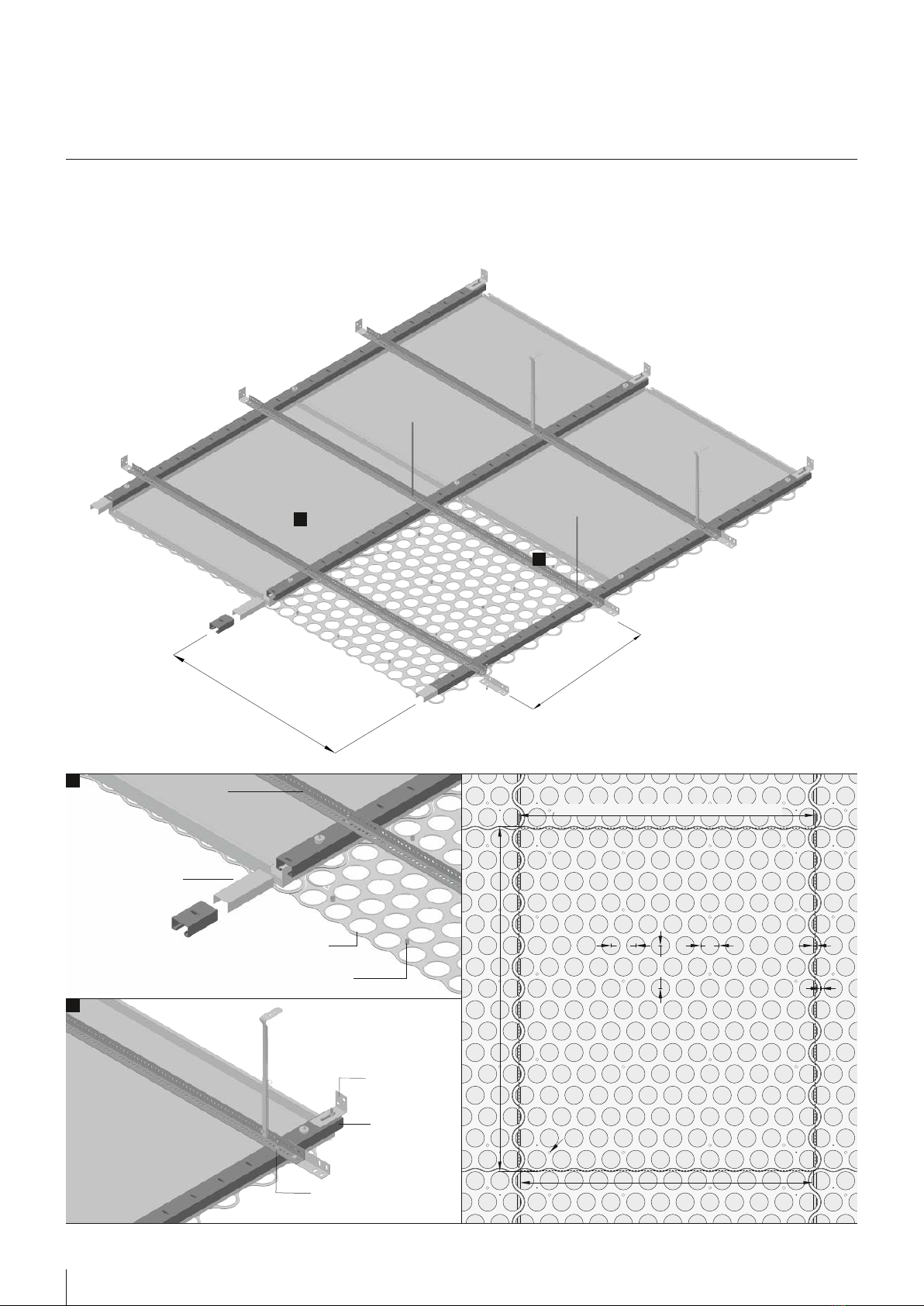
All durlum systems are systems of modular
design. This applies not only to the sub-
structure but also the ceiling parts that are
suspended, locked into place or placed
on the substructure.
durlum metal ceilings comply with the
standard EN 13964:2007 and are CE-cer-
tified.
Appropriate static certificates are avail-
able for special systems marketed by us
and for which no general approvals are
available, and appropriate designs com-
pliant with EN13964 have been construct-
ed. durlum lamps comply with standard
EN60598-1 and are CE-certified.
GUIDELINES
These installation instructions have been
structured in accordance with the require-
ment of EN 13964:2007 and describe a
proper assembly.
The description does not exempt the user
from examining the structural conditions,
implementing the building code regula-
tions and observing the information given
in the building permit prior to starting as-
sembly. They have priority, but could not
be included here.
It is advisable always to draw up assembly
diagrams/drawings, to establish the loca-
tion where assembly is to begin and to es-
tablish the required suspension points for
the relevant ceiling system prior to starting
assembly.
STRUCTURAL PRECONDITIONS
Metal ceilings may usually be installed as
soon as the building is swept clean, but
at least when all wet work in the interior
has been completed and the building has
been closed.
Prior to starting assembly, the suspension
points must be checked for their usabil-
ity, and load introduction into the building
must be guaranteed.
When using wall mounting points, such as
brackets or wall anchors, the load-carrying
capacity of the wall in question must be
checked.
If ceiling elements rest on brackets, pos-
sible wall movements must be taken into
account.
Only anchors for which a general building
supervisory approval is available may be
used, and their minimum extraction force
must be greater than 100 kg. The anchors
must be mounted as specified by the
relevant anchors manufacturer. We rec-
ommend performing regular tensile stress
tests, to verify that anchors have been set
correctly.
durlum metal ceilings are dimensioned
such that they carry their own weight of
the system construction plus a surface
load amounting to 40N/m². Higher loads
must be taken into account or suspended
separately in the construction, and the
measures must be adapted to the situa-
tion at hand. Usually, built-in components
and loads must be suspended separately.
For ceiling systems that do not allow any
tolerance compensation within a module,
GENERAL INFORMATION
suitable material expansions must be tak-
en into account.
Building expansion joints and tolerances
customary in building construction must
be taken into account accordingly.
durlum metal ceilings must always be as-
sembled by expert dry building companies
who are capable of assessing the overall
situation in the building, the metal ceil-
ing, the cladding surface, as well as the
structural conditions and are able to take
suitable precautions for ensuring proper
assembly.
If parts from different manufacturers are
used to assemble the ceiling, the relevant
mounting company must provide the cer-
tificates required by EN 13964:2007 and
must obtain suitable certificates of con-
formity itself.
Liability for proper selection of the products
and system conformity can only be as-
sumed for the systems delivered by durlum.
To prevent the parts from becoming dirty,
gloves must be worn during assembly. If
the ceiling products are delivered laminat-
ed with a protective film, they must be pro-
tected from exposure to UV radiation [sun-
light], the film must likewise be removed
from the goods no later than 4 weeks af-
ter delivery, and the storage temperature
must not exceed 30°, since otherwise the
adhesive on the panel may become hard-
ened, and the protective film can no long-
er be removed.
STORAGE
durlum metal ceilings are usually delivered
on pallets. It is advisable to leave the metal
panels on the pallets as long as possible. If
the pallets need to be opened, the durlum
POLYLAM®should always be placed on its
underside.
Storage must be carried out such that
damage is excluded.
The assembly of the ceiling panels must
not start until all dust-producing work has
been completed [swept clean].
durlum products are certified according
to ISO 9001 for development, production,
sales and also for service. Nevertheless, it is
recommended to always subject the metal
ceilings immediately to an inspection and
to report any complaints right away [usu-
ally immediately following delivery or within
3 days]. Visible damage must be noted on
the delivery note.
CERTIFICATE
The Certification Body
of TÜV SÜD Management Service GmbH
certifies that
durlum GmbH
An der Wiese 5
79650 Schopfheim
Germany
has established and applies a
Quality and Environmental Management System
for the following scope of application:
Planning, development, manufacturing and sales of
metal ceilings, functional ceilings, luminaires,
lighting and daylight systems.
Performance of audits (Report-No. 70014435)
has furnished proof that the requirements under:
ISO 9001:2008
ISO 14001:2004
ISO 50001:2011
are fulfilled. The certificate is valid from 2014-07-27 until 2017-05-29.
Certificate Registration No. 12 100/104/340 25601 TMS
Product Compliance Management
Munich, 2014-06-17

3
© durlum GmbH | www.durlum.com | Subject to changes of dimensions and design. Errors reserved. All rights reserved. | Issued: 08.11.2016
GENERAL INFORMATION
STANDARDS AND REGULATIONS
The relevant regulations applicable at the
installation site must be determined by
the assembly company in question. The
ceilings marketed by durlum conform to
EN 13964. This standard also governs fire
behaviour in accordance with EN13501.
APPLICATION
The application of durlum metal ceilings is
restricted, unless agreed upon otherwise,
to interiors, so that, pursuant to EN 13964,
class of use 1, corrosion protection class
A, has been defined here as standard. The
use of durlum lighting is restricted to interi-
ors. The lighting complies with protection
class IP20, protection class 1 according to
EN60598-1.
Should it become necessary to adjust the
metal ceiling panels to the building by cut-
ting, we recommend protecting the cut-
ting edges from corrosion by means of a
paint, to maintain the corrosion protection
class A.
QUALITY STANDARD
For material properties, dimensions, toler-
ances, colour deviations, the TAIM Direc-
tives [Technical Association of Industrial
Metal Ceiling Manufacturers] applies.
MOUNTING SEQUENCE
1. Prepare ceiling- and lighting installa-
tion plan or adopt architect's plan.
2. Check ceiling lighting installation plan
versus structural conditions.
3. Prepare a bill of materials, including a
suitable work plan and retrieval/order
of the materials required.
4. Determine the required suspension
points in accordance with the classes
of use of EN 13964. The correspond-
ing suspension distances for the dif-
ferent systems can be taken from the
detailed descriptions of the individual
ceiling systems.
5. Establish which generally approved
anchor is suitable. Check the raw cei-
ling and the walls. Mark the anchor
mounting holes and drill them. Mount
the anchors as specified by the an-
chor manufacturer and carry out ext-
raction tests using the device recom-
mended by the anchor manufacturer,
if necessary.
6. Use the same procedure when mount-
ing the wall brackets, mounting dis-
tance about 400–625 mm, check the
introduction of force into the wall.
7. Shorten intended fastening elements,
such as the M6 threaded rod or the
nonius hanger to the intended length
or order the correct length and mount
it on the raw ceiling.
8. Usually, the panel layout should be
started from the centre of the room,
in order to be able to compensate
the tolerance of the room and cut the
panels in half, if necessary. The precise
arrangement must always be done on
the basis of the ceiling layout plan.
9. durlum metal ceilings are usually pro-
vided with a cross support [primary
profile].
10. Use the layout plan to determine in
which direction the cross reinforce-
ment profiles are laid, either in parallel
to the façade [usually] or vertically to
the façade. The cross reinforcement
profiles should be mounted via a wall
anchor or via a diagonal anchoring to
prevent an axial movement. The corre-
sponding primary profiles are mount-
ed at right angles to the secondary
profiles. To this end, the system-specific
connecting elements are used, see
system descriptions. The position of the
primary profiles is established in the re-
flected ceiling plan.
11. The metal ceiling panels are often pro-
vided with a joint tape [9x3mm], to
make for easier tolerance compensa-
tion. Should a joint tape be used, the
joints must also be re-aligned from
time to time, since the joint tape also
has tolerances. However, owing to the
high production precision, it is also
possible to connect the panels without
a joint tape by using butt joints or pro-
vide them with rubber spacer naps. Al-
ways ensure that the joints are aligned.
12. If the panels are placed on a perime-
ter trim, we recommend our F-bracket
as bracket or as stepped F-bracket.
The bracket secures the panel and
protects it against lifting. The ceiling
panel is cut with electric sheet shears
[i.e. Treco shears] and adapted to the
prevailing room dimensions. When cal-
culating the minimum support area
[10mm], the dimensions of possible
wall movement should be taken into
account.
13. Attachments or other loads are to be
mounted separately. For logical rea-
sons these parts are integrated during
the mounting process.
14. After completion and pre-acceptance
of the ceiling, the sequence of joints
should be re-aligned. Soiled ceiling
panels should be cleaned to give a
perfect result for assembly.

Modulgröße ·Module size ·Tailles du module = 966 x 1115.44 mm
139,43
80,5 60
LOOP®= 1004,25 x 1124,23 mm
Langfeldplatte ·Rectangular metal panels ·Panneaux rectangulaires = 956 x 1.115 mm
10
2
Magnet ·Magnet ·Magnétique
4© durlum GmbH | www.durlum.com | Subject to changes of dimensions and design. Errors reserved. All rights reserved. | Issued: 08.11.2016
1
2
LOOP®TYPE 3 INSTALLATION MANUAL
1
2
U 1040
LOOP® steel element
W2053-ST V
Primary profile AP
Secondary profile AS
Magnet
Screw connection
W2053-ST
U1042

966
1115,44
Beispielanordnung Magnete Standardelemente
5
© durlum GmbH | www.durlum.com | Subject to changes of dimensions and design. Errors reserved. All rights reserved. | Issued: 08.11.2016
4. When assembling the LOOP®elements,
the safety rope is screwed to the LOOP®
element by means of a wing nut.
5. Measure the position of the LOOP®
element exactly using the laser (longi-
tudinal and transverse rows). Hold the
LOOP®element with the rear magnet
(20 pieces per standard element) from
below horizontally against the ceiling
S7 KS (friction force by magnet). For
the arrangement of the magnets, see
below. To simplify assembly/disassem-
bly, the magnets can be glued to the
LOOP®element (e.g. LOCTITE).
6. The installation is then performed with
further elements similar to a puzzle.
The elements are to be aligned by sli-
ding them. To do so, the joints of the
LOOP® ceiling are aligned horizontally
by pushing or pulling the adjacent ele-
ment. Check the joint between the ele-
ments for flatness and uniform width.
7. For connection to the wall, the ele-
ments can be simply adapted to the
room, using a jigsaw. The cutting edge
is covered with a bracket or a plaster-
board frieze. In the area of the glass
wall, the cut is not covered. Ensure
clean cut.
MOUNTING OF LUMINAIRES
Note:
Mounting and electrical connection of the
luminaire must be performed by an autho-
rised skilled electrician (e.g. electric instal-
ler) in accordance with VDE 0100, taking
into account the technical information
and the legal regulations in force in your
country.
Safe operation of the luminaire is only gua-
ranteed if these instructions are observed.
This is why the mounting instructions should
be kept in a safe place. The manufacturer
cannot assume any liability whatsoever if
the instructions given below are not follo-
wed or the luminaire is used improperly.
1. Remove both springs of the
PUNTEO®-J85 LED downlight.
2. When fitting PUNTEO®-J85 LED down-
lights, a connecting adapter PUNJ085-
018-Z001 is required, which is glued
centrally to the back of the element.
Attention: luminaires cannot be moun-
ted in the area of the secondary pro-
files!
3. Mount ballasts/drivers in the ceiling vo-
id, possibly on U1040.
4. Perform electrical connection of the
driver.
5. Ensure that the LOOP®elements are
clean and free of grease. To fasten
the adapter PUN J085-018-Z001 to the
LOOP®element, a primer is required.
Note: The primer is not included in the
delivery. A primer for non-absorbent
substrates, e.g. EVT Primer MK, should
be used. Attach primer to the back of
the LOOP®in the glued area. Remove
the paper from the adhesive tape of
the LOOP®adapter PUNJ085-018-Z001.
Then position and mount the adapter
on the back of the LOOP®element.
Press the adapter down firmly.
INSTALLATION MANUAL LOOP® TYPE 3
ABBREVIATIONS
AH: Distance of the suspension hangers in
axial direction of the primary profile
AP: Distance of primary profiles U1040
AS: Distance of secondary profiles W2053-
ST
ASSEMBLY OF THE FALSE CEILING
Note:
Please take the S7KS System Assembly in-
structions into account. With the following
exceptions:
Distannce of the primary profile <=800mm
Assembly of the suspension
Items 1-19 acc. to assembly instructions
Item 20
Cut the rail channel W2053-ST to the requi-
red length.
Item 21
At the crossing points to the primary profi-
le, the rail channel W2053-ST is screwed to
the L-shaped primary carrier U1040 using a
self-securing screw connection M6.
Item 22
The joint formation of the rail channel is
performed using the rail channel connec-
tor W2053-STV.
Items 23 and 24 are withdrawn
ASSEMBLY OF LOOP®ELEMENTS
1. Wear clean cotton gloves.
2. Preassemble the safety ropes (min. 2 pi-
eces per standard element) as shown
on the drawing. Run rope through the
damper disc and safety rope anchor
disc and secure it in the armature disc
by bending the web.
3. Then run the preassembled rope
through an elongated hole (in the
area of the later fastening points of the
safety rope) in the rail channel out of
the ceiling void downwards.

4. Cover plate
PUN J085 -018 -Z0 02
Cover plate
PUN J085 - 018-Z002
1. Adapter
PUN J085- 018-Z001
Knurled screws
Magnet
3.
S7 ceiling
100
6© durlum GmbH | www.durlum.com | Subject to changes of dimensions and design. Errors reserved. All rights reserved. | Issued: 08.11.2016
LOOP®TYPE 3 INSTALLATION MANUAL
6. Insert PUNTEO®-J85 laterally into the ad-
apter and position it centrally over the
hole (2.). Cutout with diameter 100mm
in S7 ceiling to be done by others if re-
quired. Then fasten the LED downlight
with the knurled screws without using
tools (3.). Place the cover plate over
the PUNTEO®-J85 on the ring (4.).
7. Connect the ballast units/drivers via
plugs. If a system is not fitted with a
plug, wiring should be carried out by a
authorised electrician.
8. Prior to acceptance, align the ele-
ments precisely, if they have been mo-
ved by other systems.
Note:
The lumininaire must not be coated
with a heat-insulating material.
The components are fitted with
electronic components, which can
become damaged in case of electrosta-
tic discharge. When handling the compo-
nents, ensure good earthing of the einvi-
ronment.
DISASSEMBLY OF THE CEILING
PANELS
9. Wear clean cotton gloves.
10. Pull LOOP®elements, including
PUNTEO®-J85 and their adapter, down-
wards to overcome their friction force.
11. LOOP®elements, including
PUNTEO®-J85 and their adapter, will fall
into the safety chain, but must always
be held.
12. Release the safety ropes and set down
the elements.
13. Open S7 false ceiling in accordance
with the S7KS Assembly Instructions.

durlum GmbH | An der Wiese 5 | D-79650 Schopfheim
T +49 (0)76 22|39 05-0
F +49 (0)76 22| 39 05-42
I www.durlum.com
CEILING LIGHTING AMBIENCE
PLAFOND LUMIERE AMBIANCE
Table of contents